Pewatron Mean Well RCP-1600 Series User manual

RCP- 00 / RHP-1U16 RCB-1600 /
User's Manual
1 RCB-1600-RHP-1U_1610-21407-0001-E-0420

0. ..............................................................................................................Safety Guidelines
1
1
1
1
1
2
4
4
7
7
20
20
7
21
21
7
7
7
9
9
9
9
9
9
9
9
9
10
10
11
12
12
14
14
5
1. ......................................................................................................................Introduction
2. ..............................................................Mechanical Specification and Inpit/Out Terminals
3. ..........................................................................................................................Functions
4.Notes on Operation............................................................................................................
1.1 .............................................................................................................
Introduction
2.1 pply Charger/
................................................................................
UnitMechanism of Su
2.2
...............................................................................Mechanism of Whole Rack System
3.1 .....................................................................................................Input Voltage Range
3.2 ................................................................................................Inrush Current Limiting
4.2 .......................................................................................................................Derating
4.1 .......................................................................................................Installation Method
3.3 .................................................................................................................Rated Power
3.4 .....................................................................................Power Factor Correction (PFC
3.5 ..............................................................................Output Voltage/Current Adjustment
3.6 ........................................................................................................Fan Speed Control
3.7 ....................................................................Short-Circuit and Over-Current Protection
3.8 ...............................................................................................Over-Voltage Protection
3.9 .......................................................................Over-Temperature protection and Alarm
3.10 ..............................................................................................................AC OK Signal
3.11 ..............................................................................................................DC OK Signal
3.12 ........................................................................Fan-Lock Protection and Alarm Signal
3.13 ..........................................................................................................Remote Control
3.14 ............................................................................................................Remote Sense
3.15 ...................................................................................................Hot-Swap Operation
3.16 .........................................................................................................
Parallel Operation
3.17
.........................................................................................................Series Operation
3.18 ..........................................................................................................Auxiliary Power
3.19
... .... .....RCP-1600 PMBus
................................ ............ ..........Communication Interface
3.20 RCB-1600 PMBus
... .... .....
................................ ............ ..Communication Interface
3.21 CANBus
... .... ..... ........
................................ ............... ... ...Communication Interface
1.3 ........................................................................................................Order Information
1.4 .......................................................................................................Main Specification
1.2 ......................................................................................................................Features
4.3 ......................................................................................................................Warranty
Version 3
2 RCB-1600-RHP-1U_1610-21407-0001-E-0420

0.Safety Guidelines
1.Introduction
RCP-1600,RCB-1600,RHP-1U User's Manual
1.1 Introduction
1.2 Features Description
1.3 Order Information
◎Please refer to the safety label on the top of the unit before (Figure 1-1~1- )use 5
Figure1-1 safety label of RCP-1600 Figure1-2 safety label of RCB-1600
◎S/upply Charger unit
1.3.1 Explanation for Encoding
1.3.2 Marking
1
Single unit : RC P -1600-
1U Rack : RHP-1U -AI
12
Output Voltage
P : Rack Power
B : Battery Charger
I : IEC320-C14 AC Inlet
T : Terminal Block
◎Risk of electrical shock and energy hazard, all failure should be examined by a qualified technician. Please do not remove the case from the
supply/charger or rack shelf unit by yourself.
◎Please do not change any component on the unit or make any kind of modification on it.
◎Please do not install the unit in places with high moisture, high ambient temperature or under direct sunlight.
◎The input voltage range is 100- 240Vac (50/60Hz), please do not feed in voltage that is over or less than 10% of that range.
◎The safety protection level of this unit is class I. The" Frame Ground"( ) on the rack shelf unit must be well connected to PE (Protective Earth).
The RCP-1600 is a rack mountable power supply that provides energy source for telecom equipments, monitoring systems, severs, etc, installing into a
19" rack shelf is required for . The RCB-1600 is a rack mountable charger, used to charge batteries, installing into a 19" rack shelf is requiredoperation
for operation.
◎44 mm low profile, suitable for standard 1U rack applications
◎Universal AC input/Full range
◎Built-in active PFC function, PF>0.98
◎Protections: short circuit/overload/over voltage /over temperature
◎Active current sharing up to 8000W (5 units) in one 19" rack up to 3 rack 15 units maximum) can be connected in parallel for RCP-1600;(shelf shelves
◎Remote control for unit of RCP/RCB-1600each 。
◎Built-in remote sense function for RCP-1600
◎Built-in battery temperature compensation function for RCB-1600
◎Output voltage programming
◎Output current programming
◎Hot Swap operation
◎AC OK and DC OK signal outputs
◎Forced air cooling by built-in DC fan with fan speed control function
◎5V/0.3A and 12V/0.8A auxiliary output
◎Built-in ORing FETs。
◎PMBus serial data transmission function
◎5 years warranty
RCP-1600-12
INPUT:
INPUT:
INPUT:
100-109VAC
110-199VAC
200-240VAC
12.5A
13.0A
10.0A
50/60Hz
50/60Hz
50/60Hz
MADE IN TAIWAN
OUTPUT : +12V
OUTPUT : +12V
OUTPUT : +12V
75A
87.5A
125A
(For INPUT 100-109VAC
(For INPUT 110-199VAC
(For INPUT 200-240VAC
MEAN WELL ENTERPRISES CO., LTD.
No. 28 Wuquan 3rd Rd., Wugu Dist.,,
New Taipei City 24891, Taiwan
Manual:www.meanwell.com/manual.html
+
RCB-1600-12
INPUT:
INPUT:
INPUT:
100-109VAC
110-199VAC
200-240VAC
12.5A
13.0A
10.0A
50/60Hz
50/60Hz
50/60Hz
MADE IN TAIWAN
(For INPUT 100-109VAC
(For INPUT 110-199VAC
(For INPUT 200-240VAC
MEAN WELL ENTERPRISES CO., LTD.
No. 28 Wuquan 3rd Rd., Wugu Dist.,,
New Taipei City 24891, Taiwan
Manual:www.meanwell.com/manual.html
OUTPUT : +14.4V
OUTPUT : +14.4V
OUTPUT : +14.4V
60A
70A
100A
+
+V ADJ +V ADJ
Bauar
Sicherheit
egel gema
tgepr uft
od
be
www.
ID 2000000000
tuv.com
wac g
os
E183223
LEVEL5
Bauar
Sicherheit
egel gema
tgepr uft
od
be
www.
ID 2000000000
tuv.com
wac g
os
E183223
LEVEL5
3 RCB-1600-RHP-1U_1610-21407-0001-E-0420

2
Figure 1-3: Safety label of RHP-1U
Figure 1-4: Safety label of the whole RHP system
◎Rack Shelf :
◎Whole system :
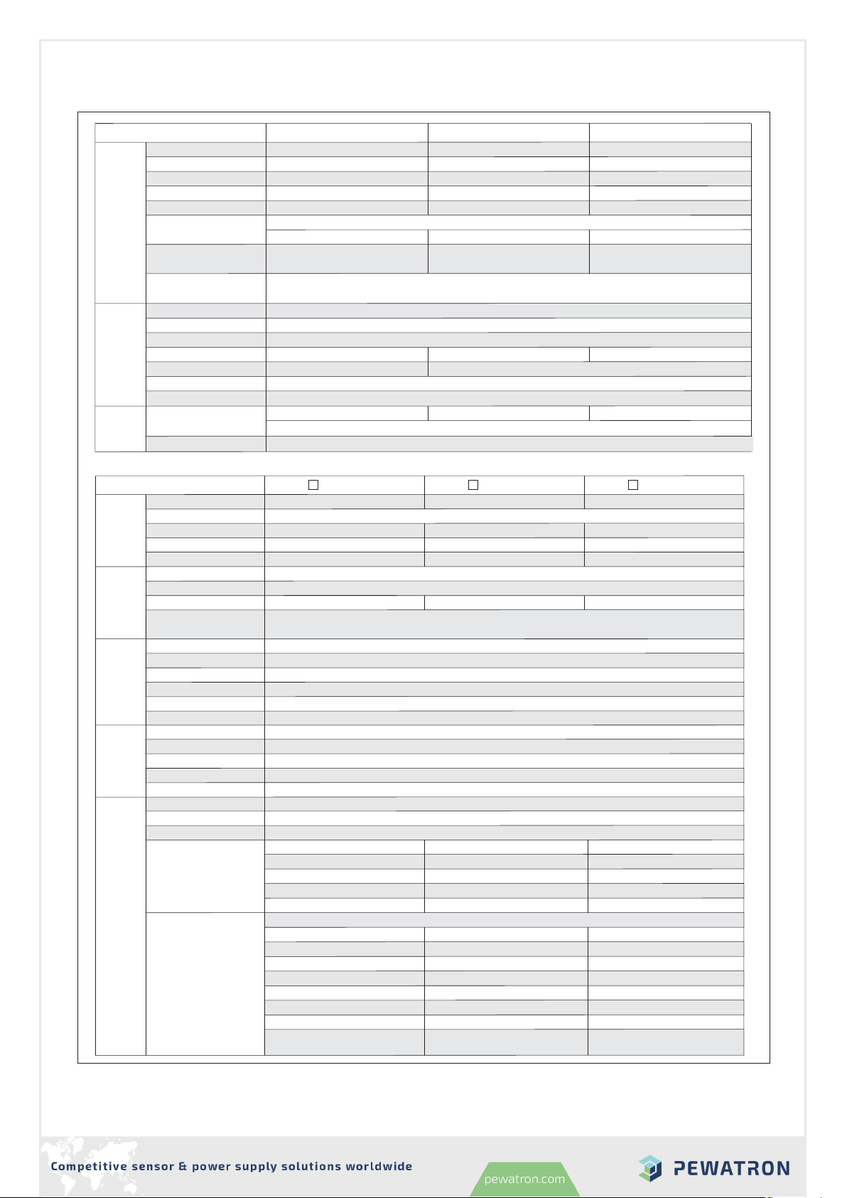
1.4 Main Specification
◎Supply/Charger unit
Figure 1-5: Safety label of the whole RHB system
Use only RCP-1600 or RCB-1600 series of identical model.
RCP-1600 series RCB-1600 series
□ 48V MODEL, Max. 5 modules provide □ 48V MODEL, Max. 5 modules provide
□ 24V MODEL, Max. 5 modules provide □ 24V MODEL, Max. 5 modules provide
□ 12V MODEL, Max. 5 modules provide □ 12V MODEL, Max. 5 modules provide
INPUT: INPUT:
INPUT: INPUT:
INPUT: INPUT:
INPUT: INPUT:
INPUT: INPUT:
INPUT: INPUT:
INPUT: INPUT:
INPUT: INPUT:
INPUT: INPUT:
100-109VAC 100-109VAC
110-199VAC 110-199VAC
200-240VAC 200-240VAC
13.5A 13.5A
13.5A 13.5A
12.5A 12.5A
OUTPUT : +48V
OUTPUT : +57.6V
OUTPUT : +28.8V
OUTPUT : +14.4V
OUTPUT : +24V
OUTPUT : +12V
OUTPUT : +48V
OUTPUT : +57.6V
OUTPUT : +28.8V
OUTPUT : +14.4V
OUTPUT : +24V
OUTPUT : +12V
OUTPUT : +48V
OUTPUT : +57.6V
OUTPUT : +28.8V
OUTPUT : +14.4V
OUTPUT : +24V
OUTPUT : +12V
20.1A 16.5A
33A
60A
40.5A
75A
23.5A 19.5A
38.5A
70A
47A
87.5A
33.5A 27.5A
55A
100A
67A
125A
14.0A 14.0A
14.0A 14.0A
13.0A 13.0A
10.5A 10.5A
10.5A 10.5A
10.0A 10.0A
50/60Hz 50/60Hz
50/60Hz 50/60Hz
50/60Hz 50/60Hz
RHP-1UI-A
Multiple power sources for configuration. Please disconnect all power sources and
refer to the user manual before any service.
The rating listed above is advised for one single module. Regarding the maximum
output current when RHP-1U is fully populated, please refer to the user manual.
WARNING :
Use only RCP-1600 or RCB-1600 series of identical model.
RCP-1600 series RCB-1600 series
□ 48V MODEL, Max. 5 modules provide □ 48V MODEL, Max. 5 modules provide
□ 24V MODEL, Max. 5 modules provide □ 24V MODEL, Max. 5 modules provide
□ 12V MODEL, Max. 5 modules provide □ 12V MODEL, Max. 5 modules provide
INPUT: INPUT:
INPUT: INPUT:
INPUT: INPUT:
INPUT: INPUT:
INPUT: INPUT:
INPUT: INPUT:
INPUT: INPUT:
INPUT: INPUT:
INPUT: INPUT:
100-109VAC 100-109VAC
110-199VAC 110-199VAC
200-240VAC 200-240VAC
13.5A 13.5A
13.5A 13.5A
12.5A 12.5A
OUTPUT : +48V
OUTPUT : +57.6V
OUTPUT : +28.8V
OUTPUT : +14.4V
OUTPUT : +24V
OUTPUT : +12V
OUTPUT : +48V
OUTPUT : +57.6V
OUTPUT : +28.8V
OUTPUT : +14.4V
OUTPUT : +24V
OUTPUT : +12V
OUTPUT : +48V
OUTPUT : +57.6V
OUTPUT : +28.8V
OUTPUT : +14.4V
OUTPUT : +24V
OUTPUT : +12V
20.1A 16.5A
33A
60A
40.5A
75A
23.5A 19.5A
38.5A
70A
47A
87.5A
33.5A 27.5A
55A
100A
67A
125A
14.0A 14.0A
14.0A 14.0A
13.0A 13.0A
10.5A 10.5A
10.5A 10.5A
10.0A 10.0A
50/60Hz 50/60Hz
50/60Hz 50/60Hz
50/60Hz 50/60Hz
RHP-1UT-A
Multiple power sources for configuration. Please disconnect all power sources and
refer to the user manual before any service.
The rating listed above is advised for one single module. Regarding the maximum
output current when RHP-1U is fully populated, please refer to the user manual.
WARNING :
Use only RCP-1600 series of identical model.
□ 48V MODEL, Max. 5 RCP-1600 modules provide
□ 24V MODEL, Max. 5 RCP-1600 modules provide
□ 12V MODEL, Max. 5 RCP-1600 modules provide
INPUT:
INPUT:
INPUT:
INPUT:
INPUT:
INPUT:
INPUT:
INPUT:
INPUT:
100-109VAC
100-109VAC
100-109VAC
110-199VAC
110-199VAC
110-199VAC
200-240VAC
200-240VAC
200-240VAC
13.5A
13.5A
12.5A
OUTPUT : +48V
OUTPUT : +24V
OUTPUT : +12V
OUTPUT : +48V
OUTPUT : +24V
OUTPUT : +12V
OUTPUT : +48V
OUTPUT : +24V
OUTPUT : +12V
20.1A
40.5A
75A
23.5A
47A
87.5A
33.5A
67A
125A
14.0A
14.0A
13.0A
10.5A
10.5A
10.0A
50/60Hz
50/60Hz
50/60Hz
RHP-8K1UI
Multiple power sources for configuration. Please disconnect all power sources and
refer to the user manual before any service.
The rating listed above is advised for one single module. Regarding the maximum
output current when RHP-1U is fully populated, please refer to the user manual.
WARNING :
Multiple power sources for configuration. Please disconnect all power sources and
refer to the user manual before any service.
The rating listed above is advised for one single module. Regarding the maximum
output current when RHP-1U is fully populated, please refer to the user manual.
WARNING :
RHB-8K1UI-X
Use only RCB-1600 series of identical model.
□ ,X=48, MODEL, Max. 5 RCB-1600 modules provide
□ ,X=24, MODEL, Max. 5 RCB-1600 modules provide
□ ,X=12, MODEL, Max. 5 RCB-1600 modules provide
INPUT:
INPUT:
INPUT:
INPUT:
INPUT:
INPUT:
INPUT:
INPUT:
INPUT:
100-109VAC
100-109VAC
100-109VAC
110-199VAC
110-199VAC
110-199VAC
200-240VAC
200-240VAC
200-240VAC
13.5A
13.5A
12.5A
OUTPUT : +57.6V
OUTPUT : +28.8V
OUTPUT : +14.4V
OUTPUT : +57.6V
OUTPUT : +28.8V
OUTPUT : +14.4V
OUTPUT : +57.6V
OUTPUT : +28.8V
OUTPUT : +14.4V
16.5A
33A
60A
19.5A
38.5A
70A
27.5A
55A
100A
14.0A
14.0A
13.0A
10.5A
10.5A
10.0A
50/60Hz
50/60Hz
50/60Hz
MADE IN TAIWAN
MADE IN TAIWAN
MADE IN TAIWAN
MADE IN TAIWAN
MEAN WELL ENTERPRISES CO., LTD.
No. 28 Wuquan 3rd Rd., Wugu Dist., New Taipei City 24891, Taiwan,
Manual:www.meanwell.com/manual.html
Bauar
Sicherheit
egel gema
tgepruft
od
be
www.
ID 2000000000
tuv.com
wac g
os
E183223
LEVEL5
Bauar
Sicherheit
egel gema
tgepruft
od
be
www.
ID 2000000000
tuv.com
wac g
os
E183223
LEVEL5
Bauar
Sicherheit
egel gema
tgepruft
od
be
www.
ID 2000000000
tuv.com
wac g
os
E183223
LEVEL5
Bauar
Sicherheit
egel gema
tgepruft
od
be
www.
ID 2000000000
tuv.com
wac g
os
E183223
LEVEL5
RCP-1600-12 RCP-1600-24
MODEL
DC VOLTAGE
RATED CURRENT
CURRENT RANGE
RATED POWER
OUTPUT VOLTAGE ADJ. RANGE Note.6
LINE REGULATION
LOAD REGULATION
SETUP, RISE TIME
HOLD UP TIME (Typ.)
VOLTAGE RANGE Note.5
FREQUENCY RANGE
POWER FACTOR (Typ.)
EFFICIENCY (Typ.)
INPUT
INRUSH CURRENT (Typ.)
LEAKAGE CURRENT
AC CURRENT (Typ.) Note.5
12V 24V
125A 67A
0 ~ 125A 0 ~ 67A
1500W 1608W
150mVp-p
11.5 ~ 15V
200mVp-p
23.5 ~ 30V
±1.0% ±1.0%
±0.5%
±0.5%
1500ms, 60ms/230VAC at full load
16ms / 230VAC at 75% load 10ms / 230VAC at full load
90 ~ 264VAC 127 ~ 370VDC
47 ~ 63Hz
0.97/230VAC at full load
88.5%
COLD START 35A/230VAC
14A/115VAC 8A/230VAC 15A/115VAC 8.5A/230VAC
<1.5mA / 230VAC
RCP-1600-48
48V
33.5A
0 ~ 33.5A
1608W
300mVp-p
47.5 ~ 58.8V
±1.0%
±0.5% ±0.5%
±0.5% ±0.5%
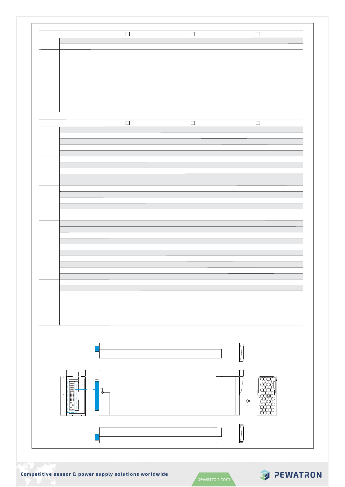
RIPPLE & NOISE (max.) Note.2
VOLTAGE TOLERANCE Note.4
91% 93%
OVER TEMPERATURE
OVERLOAD
OVER VOLTAGE
105 ~ 115% rated output power
Protection type : Constant current limiting, unit will shut down o/p voltage after 5 sec. re-power on to recover
15.75 ~ 18.75V
Protection type : Shut down o/p voltage, re-power on to recover
Shut down o/p voltage, recovers automatically after temperature goes down
31.5 ~ 37.5V 63 ~ 75V
PROTECTION
4 RCB-1600-RHP-1U_1610-21407-0001-E-0420

3
◎Rack system
RCB-1600-12 RCB-1600-24
MODEL
CURRENT RANGE
RATED POWER
OUTPUT VOLTAGE ADJ. RANGE
VOLTAGE RANGE Note.5
FREQUENCY RANGE
POWER FACTOR (Typ.)
EFFICIENCY (Typ.)
INPUT
INRUSH CURRENT (Typ.)
LEAKAGE CURRENT
AC CURRENT (Typ.) Note.5
14.4V 28.8V
13.8V 27.6V
0 ~ 100A 0 ~ 55A
1440W 1584W
11.5 ~ 15V 23.5 ~ 30V
90 ~ 264VAC 127 ~ 370VDC
47 ~ 63Hz
0.97/230VAC at full load
90.5%
COLD START 35A/230VAC
14A/115VAC 8A/230VAC 15A/115VAC 8.5A/230VAC
<1.5mA / 230VAC
RCB-1600-48
57.6V
55.2V
0 ~ 27.5A
1584W
47.5 ~ 58.8V
92% 93%
OVER TEMPERATURE
OVER VOLTAGE 15.75 ~ 18.75V
Protection type : Shut down o/p voltage, re-power on to recover
Shut down o/p voltage, recovers automatically after temperature goes down
31.5 ~ 37.5V 63 ~ 75V
PROTECTION
BOOST CHARGE VOLTAGE(Vboost)(default)
FLOAT CHARGE VOLTAGE(Vfloat)(default)
By built-in potentiometer, SVR
RECOMMENDED BATTERY
CAPACITY(AMP HOURS)
33 100 ~ 00Ah 1 0 ~ 50Ah85 92700 ~ Ah
LEAKAGE CURRENT FROM
BATTERY (Typ.) <1mA
RHP-8K1U -12 RHP-8K1U -24 RHP-8K1U -48
MODEL
VOLTAGE RANGE Note.6
RECTIFIER
OUTPUT VOLTAGE
RACK SHELF
MAX. OUTPUT CURRENT
MAX. OUTPUT POWER Note.5
FREQUENCY RANGE
AC CURRENT (Typ.) per RECTIFIER
INPUT
OUTPUT
LEAKAGE CURRENT
per RECTIFIER
90 ~ 264VAC 127 ~ 370VDC
7500W 8040W
625A 167.5A
12V
RHP-1UI-A or RHP-1UT-A
48V
RCP-1600-12 RCP-1600-24 RCP-1600-48
47 ~ 63Hz
<1.5mA / 230VAC
14A/115VAC 8A/230VAC 15A/115VAC 8.5A/230VAC 15A/115VAC 8.5A/230VAC
SAFETY STANDARDS
WITHSTAND VOLTAGE
ISOLATION RESISTANCE
WORKING TEMP.
WORKING HUMIDITY
STORAGE TEMP., HUMIDITY
TEMP. COEFFICIENT
VIBRATION
UL60950-1, TUV EN60950-1,EAC TP TC 004 approved
-30 ~ +70 (Refer to "Derating Curve")℃
20 ~ 90% RH non-condensing
-40 ~ +85 , 10 ~ 95% RH non-condensing℃
±℃ ℃0.03%/ (0 ~ 50 )
10 ~ 500Hz, 2G 10min./1cycle, 60min. each along X, Y, Z axes
ENVIRONMENT
I/P-O/P:3KVAC I/P-FG:2KVAC O/P-FG:1.5KVAC
I/P-O/P, I/P-FG, O/P-FG:100M Ohms / 500VDC / 25 / 70% RH℃
ALARM SIGNAL
REMOTE ON-OFF CONTROL
AUXILIARY POWER
Isolated TTL signal output for T-Alarm, AC-OK and DC-OK
By electrical signal or dry contact ON:short OFF:open
5V @ 0.3A, 12V @ 0.8A
FUNCTION
SAFETY &
EMC
(Note 4)
8040W
335A
24V
REMOTE SENSE Compensate voltage drop on the load wiring up to 0.5V
OUTPUT VOLTAGE PROGRAMMABLE(PV)
CONSTANT CURRENT LEVEL
PROGRAMMABLE(PC)
Adjustment of output voltage is allowable to 40 ~ 125% of nominal output voltage. Please refer to the Function Manual.
Adjustment of constant current level is allowable to 20 ~ 100% of rated current. Please refer to the Function Manual.
Parameter
Parameter
ESD
Radiated
EFT / Burst
Surge
Conducted
Magnetic Field
Voltage Dips and Interruptions
Conducted
Radiated
Harmonic Current
Voltage Flicker
Standard
Standard
EN55022 (CISPR22) / EN55011 (CISPR11)
EN61000-3-2
EN61000-3-3
EN61000-4-2
EN61000-4-3
EN61000-4-4
EN61000-4-5
EN61000-4-6
EN61000-4-8
EN61000-4-11
Test Level / Note
Test Level / Note
Class B
Class A
Class A
-----
EMC IMMUNITY
EMC EMISSION
EN55024 , EN61204-3, EN61000-6-2
Level 3, 8KV air ; Level 2, 4KV contact
Level 3
Level 3
Level 4, 1KV/Line-Line 2KV/Line-Earth
Level 3
Level 4
>95% dip 0.5 periods, 30% dip 25 periods,
>95% interruptions 250 periods
Note.8
CONSTANT CURRENT(CC)(default)
100A 55A 27.5A
5 RCB-1600-RHP-1U_1610-21407-0001-E-0420

4
NOTE
RHP-8K1U -12 RHP-8K1U -24 RHP-8K1U -48
MODEL
DIMENSION
PACKING
OTHERS
Rack 365*482.6*44(L*W*H, with mounting bracket) ; 365*440*44(L*W*H, without mounting bracket)
5.5Kg; 3pcs/17.5Kg/2.11CUFT
NOTE
RHB-8K1U -12 RHB-8K1U -24 RHB-8K1U -48
MODEL
VOLTAGE RANGE Note.2
CHARGER
RACK SHELF
CURRENT RANGE
FREQUENCY RANGE
AC CURRENT (Typ.) per CHARGER
INPUT
OUTPUT
LEAKAGE CURRENT
per CHARGER
90 ~ 264VAC 127 ~ 370VDC
0 ~ 500A 0 ~137.5A
RHP-1UI-A or RHP-1UT-A
RCB-1600-12 RCB-1600-24 RCB-1600-48
47 ~ 63Hz
<1.5mA / 230VAC
14A/115VAC 8A/230VAC 15A/115VAC 8.5A/230VAC 15A/115VAC 8.5A/230VAC
WORKING TEMP.
WORKING HUMIDITY
STORAGE TEMP., HUMIDITY
TEMP. COEFFICIENT
VIBRATION
DIMENSION
PACKING
OTHERS
-30 ~ +70 (Refer to "Derating Curve")℃
20 ~ 90% RH non-condensing
-40 ~ +85 , 10 ~ 95% RH non-condensing℃
±℃ ℃0.03%/ (0 ~ 50 )
10 ~ 500Hz, 2G 10min./1cycle, 60min. each along X, Y, Z axes
Rack 365*482.6*44(L*W*H, with mounting bracket) ; 365*440*44(L*W*H, without mounting bracket)
ENVIRONMENT
5.5Kg; 3pcs/17.5Kg/2.11CUFT
ALARM SIGNAL
REMOTE ON-OFF CONTROL
The isolated TTL signal out, Please refer to Installation Manual
By electrical signal or dry contact ON:short OFF:open
FUNCTION
SAFETY &
EMC
(Note 4)
0 ~ 275A
OUTPUT VOLTAGE PROGRAMMABLE(PV)
OUTPUT CURRENT
PROGRAMMABLE(PC)
Adjustment of output voltage is allowable to 75 ~ 125% of nominal output voltage. Please refer to the Function Manual.
Adjustment of output current is allowable to 20 ~ 100% of rated current. Please refer to the Function Manual.
14.4V 28.8V
13.8V 27.6V
57.6V
55.2V
BOOST CHARGE VOLTAGE(Vboost)(default)
FLOAT CHARGE VOLTAGE(Vfloat)(default)
TEMPERATURE COMPENSATION
-3mV / / cell / (12V = 6 cells ; 24V = 12 cells ; 48V = 24 cells)℃
SAFETY STANDARDS
WITHSTAND VOLTAGE I/P-O/P:3KVAC I/P-FG:2KVAC O/P-FG:1.5KVAC
ISOLATION RESISTANCE I/P-O/P, I/P-FG, O/P-FG:100M Ohms / 500VDC / 25 / 70% RH℃
Compliance to EN61000-4-2,3,4,5,6,8,11, EN61000-6-2 (E 50082-2), lev , criteria ANellight industry , EAC TP TC 020
Compliance to EN55022 (CISPR22) Conduction Class B, Radiation Class A ; EN61000-3-2,-3, EAC TP TC 020
EMC IMMUNITY
EMC EMISSION
AUXILIARY POWER 5V @ 0.3A, 12V @ 0.8A
Note.5
2.Mechanical Specification and Input/Output Terminals
2.1 Mechanism of Supply/Charger unit
Figure 2-1
41
85
Air flow
direction
300
11max.
9max.
LED Status Indicator
42.5
12.5
5.8
7.7
3.6
CN1
62.4
SVR
7
50
1. All parameters NOT specially mentioned are measured at 230VAC input, rated load and 25 of am ient temperature.℃
2. Ripple & noise are measured at 20MHz of andwidth y using a 12" twisted pair-wire terminated with a 0.1uf & 47uf parallel capacitor. Under parallel
operation of more than one rack connecting together, ripple of the output voltage may e higher than the SPEC at light load condition. It will go ack to
normal ripple level once the output load is more than 5%.
3. Tolerance : includes set up tolerance, line regulation and load regulation.
4. The power supply is considered a component which will e installed into a final equipment. All the EMC tests are een executed y mounting the unit on
a mm* mm metal plate with 1mm of thickness. The final equipment must e re-confirmed that it still meets EMC directives.1000 1300 For guidance on how
to perform these EMC tests, please refer to EMI testing of component power supplies. (as availa le on http://www.meanwell.com)
5. Output of all the RCP-1600 modules are connected in parallel in the rack.
6. Derating may e needed under low input voltages. Please check the static characteristics for more details.
7. Because of component tolerance, there is a possi ility that some of units connected in parallel will reach an overcurrent limit then overloading the other
units when operating at full load condition. If overload conditions happen in parallel usage, it is suggested that derate the total output current y 10%.
8. The equivalent leakage current of the system is determined y the quantity of populated rectifiers.
9. The am ient temperature derating of 3.5 /1000m with fanless models and of 5 /1000m with fan models for operating altitude higher than 2000m(6500ft).℃℃
UL60950-1, TUV EN60950-1 EAC TP TC 004 approved,
1. All parameters NOT specially mentioned are measured at 230VAC input, rated load and 25 of am ient temperature.℃
2. Derating may e needed under low input voltages. Please check the static characteristics for more details.
3. The power supply is considered a component which will e installed into a final equipment. All the EMC tests are een executed y mounting the unit on
a mm* mm metal plate with 1mm of thickness. The final equipment must e re-confirmed that it still meets EMC directives.720 360 For guidance on how
to perform these EMC tests, please refer to EMI testing of component power supplies. (as availa le on http://www.meanwell.com)
4. Output of all the RCB-1600 modules are connected in parallel in the rack.
5. The equivalent leakage current of the system is determined y the quantity of populated rectifiers.
6. The am ient temperature derating of 3.5 /1000m with fanless models and of 5 /1000m with fan models for operating altitude higher than 2000m(6500ft).℃℃
6 RCB-1600-RHP-1U_1610-21407-0001-E-0420

5
2.2 Mechanism of whole Rack system
Module AModule BModule CModule DModule E
466.2
482.6
5-M4 L=4
4-M8 L=16
4-M8 L=16
440
5-M4 L=4
RHP-1UI
CN2
CN2
CN1
CN1
RHP-1UT
L
10 8.2
NFG L
10 8.2
NFG L
10 8.2
NFG L
10 8.2
NFG L
10 8.2
NFG
2525 9.59.5
11.611.6
2222
20.720.7
STATUSSTATUSSTATUSSTATUSSTATUS
7
10.2
35
SVR SVR SVR SVR SVR
29.5
7.4
Air flow
direction
44
14 max.
8.4
24
24
7.65
7.65
306
365
E
E
D
D
C
C
B
B
A
A
ADDRESS
ADDRESS
ADDRESS
ADDRESS
ADDRESS
ADDRESS
ADDRESS
ADDRESS
ADDRESS
ADDRESS
SWITCH
SWITCH
SWITCH
SWITCH
SWITCH
SWITCH
SWITCH
SWITCH
SWITCH
SWITCH
IEC320-C14 IEC320-C14 IEC320-C14 IEC320-C14 IEC320-C14
1
88
1
JK1
JK1
Figure 2-2
4
426
2
22
11
13
325
26
25
2
1
42
13
26
25
2
1
7 RCB-1600-RHP-1U_1610-21407-0001-E-0420

6
※Connector Pin No. Assignment (CN2)
Note3 Wiring cable of CN2 varies in rack shelf with RCP 1600 RCB 1600 please follow the discription below to select the:--,or
correct cable for wiring, DO NOT make it misplaced!
※LED Status Indicators & Corresponding Signal at Function Pins
For power supply system
For charger system
※Connector Pin No. Assignment (CN1)
LED
Green
Orange
Red
Float(stage 3)
Charging (stage 1 or stage 2)
Description
The LED will present a constant red light when the abnormal status (OTP,
OLP, fan fail and charging timeout) arises.
LED
Green
Red
Red Flashing()
Red(Flashing)
The power supply functions normally
Description
The LED will present a constant red light when the abnormal status (OTP,
OLP, fan fail and charging timeout) arises.
The LED will flash with the red light when the internal temperature reaches
60 ; under this condition, the unit still operates normally without entering℃
OT . (In the meantime, an alarm signal will be sent out through the PMBusP
interface.)
The LED will flash with the red light when the internal temperature reaches
60 ; under this condition, the unit still operates normally without entering℃
. (In the meantime, an alarm signal will be sent out through the PMBusOTP
interface.)
◎The RED wiring cable goes with the RCP-1600, used to compensate voltage drop on the load wiring.
Figure 2-3 RCP/RCB-1600 front panel
LED Status Indicator
1,5,9,13,17 AC-OK
Description
Pin No. Function
2,6,10,14,18
DC-OK
The unit can turn the output ON/OFF by electrical signal or dry contact between Remote ON-OFF and +5V-AUX. (Note.2)
Short (4.5 ~ 5.5V) : Power ON ; Open (0 ~ 0.5V) : Power OFF ; The maximum input voltage is 5.5V.
3,7,11,15,19
Remote
ON-OFF
4,8,12,16,20
T-ALARM
Auxiliary voltage output, 4.5~5.5V, referenced to GND-AUX (pin 22).
The maximum load current is 0.3A. This output has the built-in "Oring diodes" and is not controlled by the remote ON/OFF control.
21 +5V-AUX
Auxiliary voltage output GND. The signal return is isolated from the output terminals (+V & -V).
Auxiliary voltage output, 10.8~13.2V, referenced to GND-AUX (pin 22).
The maximum load current is 0.8A. This output has the built-in "Oring diodes" and is not controlled by the remote ON/OFF control.
22
23
GND-AUX
+12V-AUX
High (4.5 ~ 5.5V) : When the internal temperature exceeds the limit of temperature alarm, or when fan fails.
Low (-0.1 ~ 0.5V) : When the internal temperature is normal, and when fan normally works.
The maximum sourcing current is 10mA and only for output(Note.2)
24 -V(Signal) Negative output voltage. For local sense use only; It can't be connected directly to the load.
Connection for output voltage programming. The voltage can be trimmed within its defined range. (Note.1)
26
25
PV
Connection for output current programming. The current can be trimmed within its defined range. (Note.1)
PC
The maximum sourcing current is 10mA and only for output. (Note.2)
Low (-0.1 ~ 0.5V) : When the input voltage is 75Vrms.≦
High (4.5 ~ 5.5V) : When the input voltage is 87Vrms .≧
Low (-0.1 ~ 0.5V) : When Vout 80% 5%.≧±
The maximum sourcing current is 10mA and only for output. (Note.2)
High (4.5 ~ 5.5V) : When the Vout 80% 5%.≦±
For power supply system
Low (-0.1 ~ 0.5V) : When Vout 8V/16V/32V . The maximum sourcing current is 10mA and only for output. (Note.2)≧±1V
DC OK is associated with battery low protection.
High (4.5 ~ 5.5V) : When the Vout 8V/16V/32V .≦±1V
For charger system
Note.1: Non-isolated signal, referenced to [-V(signal)].
Note.2: Isolated signal, referenced to GND-AUX.
Positive sensing. The +S signal should be connected to the positive terminal of the load. The +S and -S leads should be
Negative sensing. The -S signal should be connected to the negative terminal of the load. The -S and +S leads should be
twisted in pair to minimize noise pick-up effect. The maximum line drop compensation is 0.5V.
3
4
1
For power supply system
2
+V(Signal)
-V(Signal)
+S
-S
Positive output voltage. For local sense use only, can't be connected directly to the load.
Negative output voltage. For local sense use only, can't be connected directly to the load.
26
4
2
2
1
1
25
3
8 RCB-1600-RHP-1U_1610-21407-0001-E-0420

1
8
8
1
※Connector Pin No. Assignment( ) : RJ45 8 positionsJK1
7
3.Functions
3.1 Input Voltage Range
3.2 Inrush Current Limiting
3.3 Output Power
◎Front end unit
◎Whole System
RCP-1600-12 : 1500W (12V / 125A) RCB-1600-12 : 14.4V / 100A
RKP-8K1U -12 : 7500W (12V / 625A) RHB-8K1U -12 : 14.4V / 500A
RKP-8K1U -24 : 8040W (24V / 335A) RHB-8K1U -24 : 28.8V / 275A
RKP-8K1U -48 : 8040W (48V / 167.5A) RHB-8K1U -48 : 57.6V / 137.5A
RCP-1600-24 : 1608W (24V / 67A) RCB-1600-24 : 28.8V / 55A
RCP-1600-48 : 1608W (48V / 33.5A) RCB-1600-48 : 57.6V / 27.5A
3.5 Output voltage/Current adjustment
3.5.1 Adjustment of single unit
Output voltage can be trimmed by adjusting SVR1 (which can be found under the small circular hole, located on the top of the unit). Please utilize
an insulated cross-head screwdriver to make an adjustment.
3.4 (PFC)nPower Factor Correctio
◎Built-in active power factor correction (PFC) function, power factor (PF) will be 0.98 or better when the input voltage is in a range of 90 -230Vac
and operated at full load condition.PF will be less than 0.98 if the output is not at full load or the input voltage is higher than 230Vac.
◎The Black wiring cable goes with the RCB-1600, used for battery temperature compensation.
◎.The input voltage rang is orAC90~264V DC127~370V
◎To insure proper operation, AC input should be within the pre-specified range.A wrong input will cause the supply/ operating improperly,charger units
losing PFC function or even damaging the unit in worst scenarios.
◎The efficiency will be lower and the to a predetermined safe value if the units are applied with a loweroutput current will be automatically limited
input voltage. Please refer to 4.2 Derating for more information.
◎.Built-in inrush current limiting circuit
◎If adding an external switch (relay/circuit break) at the input side is required, choose switches that are able to withstand inrush current of the units.
◎Since the inrush limiting circuit mainly consists of a thermistor and a relay, inrush current will be much higher than the specified value if input
thermistor is not allowed sufficient time to cool down. After turning off the supplys/chargers, a 10 second cool down period is recommended before
turning them on again.
Pin No.
1,2
3
4
5
7
6
Function
DA,DB
-V(signal)
CONTROL
NC
SCL
SDA
Description
Differential digital signal for parallel control. (Note.1)
Remote ON-OFF control pin used in the PMBus interface. (Note.2)
Retain for future use.
Serial Data used in the PMBus interface. (Note.2)
Serial Clock used in the PMBus interface. (Note.2)
8GND-AUX Auxiliary voltage output GND. The signal return is isolated from the output terminals (+V & -V).
Note.1: Non-isolated signal, referenced to [-V(signal)].
Note.2: Isolated signal, referenced to GND-AUX.
Negative output voltage signal.
It is for local sense and certain function reference; it cannot be connected directly to the load.
3,4 NC Not use.
Temperature sense associated with the temperature compensation funcion.
1RTH+
2RTH-
◎For charger system
9 RCB-1600-RHP-1U_1610-21407-0001-E-0420

8
Figure 3-2
Note The RCP-1600 will trigger OLP to shut down itself if the output stays on constant current level condition for more than 5 seconds.:
3.5 3.Output current adjustment function(Output current trimming )
※Constant current level(RCP-1600)/output current (RCB-1600) can be adjusted within a range of 20-100% of the rated current via an external DC
source, the wiring is show as below.
VV 55
External voltage (DC)External voltage (DC)
4.74.7
Non-LinearNon-Linear
11
RCB-1600-12RCP-1600-12
0.40.4
97.2
1212
1515
RCB-1600-24RCP-1600-24
00
189.6 3619.2
2424 4848
3030 6060
RCB-1600-48RCP-1600-48
00 00
OUTPUT VOLTAGE(V)
OUTPUT VOLTAGE(V)
Connection between +S & +V, -S & -V on CN1 is required (RCP-1600system)
Relationship between the output current and the external DC source is shown as below.
◎SystemRCP-1600 ◎SystemRCB-1600
+V
-S
CN2 +S
-V
RHP-1U System
LOAD
PC
CN1 -V Signal
EXTERNAL
VOLTAGE
25
24
1
2
Iout
V
0.4 1 4.7 5
20
100
External voltage (VDC)
OUTPUT CURRENT (%)
Non-Linear
110
Iout
V
0.4 4.7
20
100
External voltage (VDC)
OUTPUT CURRENT (%)
Non-Linear
51
3.5.2 Voltage adjustment of whole rack system by an external 0 -5 Vdc source (output voltage trimming function)
PV
26
0~5V
(1) Connect output of the external DC source to PV(PIN 26) and –V(PIN 24) on CN1, as shown in Figure3-1.
(2) Relationship between the output voltage and the external DC is shown in Figure3-2.source
(3) When increase the output to a higher voltage level, please reduce the load current accordingly. Output wattage of each unit should not
exceed the rated value under any circumstance.
Figure 3-1 Connection of external DC voltage source
24
-V
10 RCB-1600-RHP-1U_1610-21407-0001-E-0420

9
3.6 Fan Speed Control
3.7 Short Circuit Protection & Over Current Protection (only for RCP-1600)
3.8 Over Voltage Protection (OVP)
3.9 Over Temperature Protection (OTP) and Alarm
◎Built-in fan speed control circuit, the fan speed changes epending on the internal temperature.automatically d
◎The protection activates when the output is short-circuited or the output current exceeds 110%±5% of the rated output current. Re-power on to recover
when the short-circuit/overload condition is removed.
◎Built-in 2 sets of thermal detection circuit, once the internal temperature exceeds a threshold value, the unit will shut down automatically (the fans wills
still be operating to cool down the unit). Please switch off the AC input, remove all possible causes and then leave the units cooling down to normala
working temperature (approximate 10 minutes – 1 hour) before repower on again.
◎℃When the internal temperature reaches 60 , trigger point of a thermal alarm, the red LED on the front panel will flash and there will be an alarm signal
sent out through the PMBus interface (refer to 3.19). Even so, the units still operate normally.
◎When the internal temperature is within a normal value, there will be a "LOW" signal (-0.1 -0.5V) sent out through T-ALARM on CN1; there will be a "HIGH"
signal (4.5 -5.5V) sent out through T-ALARM on CN1 when internal temperature exceeds a certain value. (referenced to GND-AUX).
◎Maximum output current: 10mA.
◎Built-in over voltage protection circuit for every single units.
OVP triggering points vary in different output models. Please refer to the specification sheet for detailed information.◎
◎Once OVP is triggered, leave the units off for 10 seconds before recyclingAC again.
3.12 Fan-lock Protection & Alarm Signals
3.13 Remote Control
◎Built-in fan-lock protection circuit, the output will shut off when the DC fans stop operating (fan-lock or broken wires). In the meantime, there will
be a “HIGH” signal sent out through T-ALARM, referenced to GND AUX. Please remove the unit from your system and send back to our local-
distributor or MEAN WELL for repair.
Maximum output current 10mA.
◎
Whole rack system ON/OFF Single unit ON/OFF
Figure 3-3 Connection of Remote Control
Between CN1 ON/OFF
and +5V-AUX
SW Open
SW Short
Output
OFF
ON
3.11 DC OK signal
+5V-AUX +5V-AUX
ON/OFF ACN1 CN1 ON/OFF A
ON/OFF B ON/OFF B
ON/OFF C
ON/OFF D ON/OFF D
ON/OFF E ON/OFF E
ON/OFF C
RHP-1U System RHP-1U System
33
77
11
15
19
11
15
19
21 21
3.10 AC OK signal
◎Built-in AC input voltage detection circuit.
When AC input voltage rms, the output voltage can start working normally and there will be a “ ” signal( . - .5V) sent out AC-OK n≧87V HIGH 4 5 5 o◎through
CN1. ( GND-AUX).referenced to
When AC input voltage rms, The output voltage shuts off and the red LED on the fron panel will light up. In the mean time, there will be a ” ”≦75V LOW◎
signal (- . - .5V) sent out AC-O . ( - ).0 1 0 K on CN1 referenced to GND AUXthrough
Maximum output current10mA.◎
◎.Built-in DC output voltage detection circuit
◎When DC output voltage is within a normal value, there is a “LOW”(-0. -0.5V) signal sent out DC-OK . ( - ).1 on CN1 referenced to GND AUXthrough
◎ -When DC output voltage is out of normal range, there is a “HIGH”(4.5-5.5V) signal sent out . ( - ).DC OK on CN1 referenced to GND AUXthrough
◎Maximum output current 10mA.
◎Built-in remote control circuit, refer to Figure3-3 for control methods of single unit or whole rack system.ON/OFF
◎Please be aware that “ON/OFF”and “+ V-AUX” n CN1 should be linked together to allow the units operate normally; If , there will be no5 o kept open
output voltage.
◎Maximum input voltage 5.5V.
3.14 Remote Sense (only for RCP-1600)
◎.Built-in remote sense circuit that is able to compensate voltage drop up to 0.5V
When using this function, the sensing wires should either be twisted or shielded to prevent external noise interference (refer to Figure 3-4).◎
Voltage drop across the output wires must be limited to less than 0.5V. Also wires with adequate current rating should be used between◎+V,-V and the
loads. Please firmly connect the output wires to prevent them from loosing, or the power supply may be out of order.
The +S and –S have to be connected to the +V(signal) and –V(signal), respectively, as shown in Figure 3-5, which is Local Sense, in order to get the◎
correct output voltage if Remote Sense is not used. Otherwise, the output voltage will increase to a extremely high level which may trigger OVP.
11 RCB-1600-RHP-1U_1610-21407-0001-E-0420

10
CN2
CN2
LOAD
-V
+V
Figure Connection of3-4 Remote Sense
Figure Connection of3-5 Local Sense
3
1
2
2
1
4
RHP-1U
RHP-1U
-V
-V
+V
+V
+S
+S
-S
-S
Twisted wires
3.15 Hot Swap Operation
◎Built-in "Oring MOSFET", the units can be installed/removed without tuning power off.
Insert units: Grasp the handle and push into the rack shelf through the rail.◎
◎Pull out units: Press the clip shown in Figure 3-7 and pull it out.
Caution: Please use adequate force to insert the RCP/RCB-1600 into the rack . Slamming units into the rack can damage the connectors bothshelf
on the rear of the units and inside the rack.
Figure 3-7 Illustration of how to remove the RCP/RCB-1600 from a rack
Press down
Figure 3-6 Illustration of how to insert the RCP/RCB-1600 into a rack
"Click"
3.16 Parallel Operation
◎P shelfarallel operation in a single rack is only suitable for the identical units (with the same model and the same output voltage/current).
Each rack shelf (RHP-1U ) has built-in parallel connection/wiring. Once RCP or RCB units insert in the rack shelf thenhave ed heset◎
.front end unit are operated in parallel
.Please refer to 3.13 & 3.14 for the connection/wiring of other functions◎
3.16.1 Operation of Single Rack Shelf
12 RCB-1600-RHP-1U_1610-21407-0001-E-0420

3.17 Series Operation
◎Higher output voltage can be acquired by connecting rack shelves in series.
The rack shelves (RHP-1U ) connected in series should have the identical units. Please refer to Figure3-9 for wiring◎
configuration.
Total output current should not exceed currents that can be produced in each rack shelf.◎
Difference of rise time in each unit may lead to steps/stairs like turn on.◎
The total amount of output voltage in series should be less than 60Vdc [the requirement of SELV (Safety Extra Low Voltage) of IEC60950-1].◎
It is suggested that add external diodes (*) on the output, shown in Figure 3-9, to prevent reverse voltage. Rating of these diodes should be◎
higher than the total amount of output voltage and current.
RHP-1U#1
RHP-1U#2
A
ON/OFF
3 7 11151921
+V
+S
-S
-V
B
ON/OFF
C D E +5V-AUX
ON/OFF ON/OFF ON/OFF
+V
-V
LOAD
+V
+S
23
22
22
(*)
Figure 3-9 Configuration of rack shelf units in series
A
ON/OFF
3 7 11151921
B
ON/OFF
C D E +5V-AUX
ON/OFF ON/OFF ON/OFF -S 23
-V
(*)
11
◎Parallel operation is only suitable for the identical units (with the same model and the same output voltage/current). Up to 3 rack shelves
and the maximum supply units that can be connected in parallel is 15.
Because of component tolerance, there is a possibility that some of the units connected in parallel will reach an overcurrent limiting then◎
overloading the other units when operating at full load condition. It is suggested that reduce the total output current by 10%.
For example: RCP-1600-24x15 connected in parallel (in 3 rack shelves), the total output current should be to 67Ax15unitx0.9reduced
=904.5A.
Difference of output voltage among parallel units should be less than 0.2V.◎
Co rack shelf units in parallel before ing to the load. Do not connect rack shelf units to the load separately. Refer to Figure 3-8nfigure connect◎
Control singles of DA, DB and V should also be connected in parallel. (Refer to Figure 3.8).–◎
Use twisted wires for the wiring of +S and S, the twisted wires should not touch the load wires to avoid interference. Refer to Figure 3-8.–◎
A too long cable length might be with a higher amount of noise that affects rack units proper operation in parallel. To reduce the noise,'◎
installing termination resistors, an accessory, to the unused JK1 is recommended.
3.16.2 Operation of three rack shelves in parallel (RCP-1600 system)
JK1
JK1
CN1
-V
-V
DB
DBDB
DA
DADA
+S
-S
+5V-AUX
+5V-AUX
ON / OFF-A
ON / OFF-A
ON / OFF-B
ON / OFF-C +V -V
}
}
+V
LOAD
RHP-1U#1
RHP-1U#2
ON / OFF-E
ON / OFF-D
CN2
CN1
ON / OFF-B
ON / OFF-C
ON / OFF-D
ON / OFF-E +V
-V
-V
JK1
DADA
CN1
-V
DBDB
+5V-AUX
ON / OFF-A
ON / OFF-B
}
RHP-1U#3
ON / OFF-C
ON / OFF-D
ON / OFF-E +V -V
Twisted wires
Figure 3-8 Configuration of three rack shelf units in parallel
◎Under operation of more than one rack shelf in parallel, value of Ripple & Noise may be larger than that stated in the specification at light load or
no condition. It will return to normal level once the loads draw more current than 10% of the total rating.
13 RCB-1600-RHP-1U_1610-21407-0001-E-0420

3.19.1 RCP-1600 PMBus Addressing
12
◎Each RCP-1600 unit should have their unique and own device address to communicate over the PMbus. 7-bit address setting pins are
used to assign a device address for a RCP-1600 unit, as shown in the description below.
3.18 Auxiliary Output
3.19 RCP-1600 PMBus Communication Interface
◎Built-in 5V/0.3A and 12V/0.8A auxiliary output.
◎RCP-1600 is compliant with PMBus Rev.1.1, the maximum communication speed is 100KHz and it has the capability of identifying up to16
addressed units.
PMBus information scommunication interface is able to provide the current operating status and as follow :◎
◎RKP-CMU1 is a monitor unitparticularly designed for rack power.
◎Maximum number that can be monitored by master controller in communication shall be 15 power supplies.
1
MSB
0 0 A3 A2 A1 A0
LSB
1 2 3 4
ON
Module
No.
Module
No.
11
A0 A0
0
1
2
3
4
5
6
7
8
9
10
11
12
13
14
15
22
A1 A1
33
A2 A2
44
A3 A3
ON
ON
ON
ON
ON
ON
ON
ON
OFF
OFF
OFF
OFF
OFF
OFF
OFF
OFF
ON ON
ON ON
ON ON
ON ON
OFF OFF
OFF OFF
OFF OFF
OFF OFF
ON ON
ON ON
ON ON
ON ON
OFF OFF
OFF OFF
OFF OFF
OFF OFF
ON
ON
ON
ON
ON
ON
ON
ON
OFF
OFF
OFF
OFF
OFF
OFF
OFF
OFF
Device address Device address
DIP switch position DIP switch position
Table 3-1
1 Output voltage current and internal temperature..,
2 Alarm and status..
.3 Manufacturers and model data.
◎A0-A3 allow users to designate the address for each RCP-1600 unit; these four bits are defined through a 4-pole DIP switch on the rear panel
of the rack shelf. There are up to 16 different addresses are available to be assigned. When DIP switch in the “ON” position means logic “0”;
when it is in the “OFF” position, meaning logic “1”, for example, position 3 in “OFF”, the corresponding bit, A2, is set to logic “1”. Please refer to
Table 3-1 for the detailed setup advice.
14 RCB-1600-RHP-1U_1610-21407-0001-E-0420

3.19.2 PMBus Command List
13
◎The command list of the RCP-1600 is shown in Table 3- . It is compliant with the standard protocol of PMBus Rev. 1.1. For more detailed2
information, please refer to PMBus official website http://pmbus.org/specs.html).(
Command
Code
01h
02h
19h
20h
21h
# of data
Bytes
1
1
1
1
2
Description
Remote ON/OFF control
ON/OFF function configuration
Capabilities of a PMBus device
Define data format for output voltage
(format: Linear, N= -9)
Output voltage setting value
(format: Linear, N= -9)
Command
Name
OPERATION
ON_OFF_CONFIG
CAPABILITY
VOUT_MODE
VOUT_COMMAND
Transaction
Type
R/W Byte
Read Byte
Read Byte
R Byte
R Word
22h 2 Output voltage trimmed value
(format: Linear, N= -9)
Output overcurrent setting value
(format: Linear, N= -2)
VOUT_TRIM R/W Word
47h
79h
7Ah
7Bh
7Ch
7Dh
1
2
1
1
1
1
Define protection and response when an
output overcurrent fault occurred
Summary status reporting
Output voltage status reporting
Output current status reporting
AC input voltage status reporting
Temperature status reporting
IOUT_OC_FAULT_RESPONSE
STATUS_WORD
STATUS_VOUT
STATUS_IOUT
STATUS_INPUT
STATUS_TEMPERATURE
R Byte
R Word
R Byte
R Byte
R Byte
R Byte
81h
80h
88h
7Eh
8Bh
8Ch
1
1
2
1
2
2
Fan1 and 2 status reporting
Manufacture specific status reporting
AC input voltage reading value
(format: Linear, N=-1)
Communication, logic,
Memory status reporting
Output voltage reading value
(format: Linear, N= -9)
Output current reading value
(format: Linear, N= -2)
STATUS_FANS_1_2
STATUS_MFR_SPECIFIC
READ_VIN
STATUS_CML
READ_VOUT
READ_IOUT
R Byte
R Byte
R Word
R Byte
R Word
R Word
46h 2IOUT_OC_FAULT_LIMIT R/W Word
90h
91h
98h
2
2
1
Fan speed 1 reading value
(format: Linear, N= 5)
Fan speed 2 reading value
(format: Linear, N= 5)
The compliant revision of the PMBus
(default: 11h for Rev. 1.1)
READ_FAN_SPEED_1
READ_FAN_SPEED_2
PMBUS_REVISION
R Word
R Word
R Byte
8Dh 2 Temperature 1 reading value
(format: Linear, N= -3)
READ_TEMPERATURE_1 R Word
Table 3-2
99h
9Ah
9Bh
9Ch
9Dh
9Eh
12
12
6
3
6
12
Manufacturer's name
Manufacturer's model name
Firmware revision
Manufacturer's factory location
Manufacture date. (format: YYMMDD)
Product serial number
MFR_ID
MFR_MODEL
MFR_REVISION
MFR_LOCATION
MFR_DATE
MFR_SERIAL
Block Read
Block Read
Block Read
Block R/W
Block R/W
Block R/W
15 RCB-1600-RHP-1U_1610-21407-0001-E-0420

PMBus command
READ_VIN
READ_TEMPERATURE_1
READ_FAN_SPEED_1
READ_FAN_SPEED_2
READ_VOUT
READ_IOUT
(Note. 1)
Range
80 ~ 264V
-40 ~ 100℃
0 ~ 20000RPM
0 ~ 20000RPM
0 ~ 15V
0 ~ 150A
0 ~ 30V
0 ~ 80A
0 ~ 60V
0 ~ 40A
Tolerance
±10V
±℃5
±2000RPM
±2000RPM
±0.18V
±2.5A
±0.36V
±1.34A
±0.48V
±0.67A
Model
ALL
ALL
ALL
ALL
12V
12V
24V
24V
48V
48V
Table 3-3
3.19.3 PMBusData Range and Tolerance
◎Display parameters
PMBus command
OPERATION
IOUT_OC_FAULT_LIMIT
VOUT_COMMAND
(Note. 2)
VOUT_TRIM
(Note. 2)
Adjustable range
00h(OFF) / 80h(ON)
25 ~ 137.5A
13.5 ~ 73.5A
6.75 ~ 36.75A
-4.8 ~ 3V
-14.4 ~ 6V
-28.8 ~ 12V
Tolerance Default
N/A
N/A
N/A
N/A
80h(ON)
±2.5A
±1.34A
±0.67A
137.5A
73.5A
36.75A
±0.18V
±0.36V
±0.48V
0V
0V
0V
Model
ALL
12V 12V 12V
12V
12V
24V 24V 24V
24V
24V
48V 48V 48V
48V
48V
Table 3-4
◎Control parameters
14
Adjustable voltage
Minimum readable current
Model
Model
12V
12V
7.2 ~ 15V
5A 1A±
24V
24V
9.6 ~ 30V
2.7A 1A±
48V
48V
19.2 ~ 60V
1.3A 1A±
Table 3-6
Table 3-5
Note:
2.When using PMBus to adjust output voltage, VOUT_COMMAND only can be used to display the rated voltage of the unit and cannot be .written
It is VOUT_TRIM that . Taking RCP-1600-12 as an example, to get a 7.2V output, please value ofsets the amount of trimmed voltage set
VOUT_TRIM to -4.8V. Adjustable voltage range for each model is shown as below.
1.READ_IOUT will display ZERO amp when output current is less than values in the table below.
3.20 RCB-1600 PMBus Communication Interface
◎RCB-1600 is compliant with PMBus Rev.1.1, the maximum communication speed is 100KHz and it has the capability of identifying up to 8
addressed units.
PMBus communication interface is able to provide the current operating status and data as the following:◎
1.Output voltage, current and internal temperature.
Alarm and status.2.
3 Manufaturers and model data..
.4. ead/write of charge curve settingsR
16 RCB-1600-RHP-1U_1610-21407-0001-E-0420

15
1 2 3 4
ON
Module
No.
1
A0
0
1
2
3
4
5
6
7
2
A1
3
A2
ON
ON
ON
ON
OFF
OFF
OFF
OFF
ON
ON
ON
ON
OFF
OFF
OFF
OFF
ON
ON
ON
ON
OFF
OFF
OFF
OFF
Device address
DIP switch position
Table 3-7
Table 3-8
Figure 3-10
D0
DIP switch position 4
Function describe
ON Charging curve
OFF PMBus or V PC or SVR controlP/
3.20.2 Charge Curve
3.20.1 PMBus Device Addresing and Charge Mode Selection
*The charging operation can be determined by the setup over D0, position 4 on the DIP switch. When D0 is “ON”, RCB-1600 follows a built charging curve
to charge the batteries; when D0 is “OFF”, the charging operation is completely defined by the control over PMBus, PV/PC or SVR. Please refer to Table 3-7
(right).
1
MSB
0 0 0 A2 A1 A0
LSB
◎Suitable for lead-acid batteries (flooded, Gel and AGM) and
Li-ion batteries (lithium iron and lithium manganese).
◎Default 3 stage charging curve ◎Embedded 3 stage charging curve
Charge Current
Constant Current
stage 1 stage 2 stage 3
Constant Voltage Float
Start
3 Stage
Charge Voltage
100% CC
10% CC
boost
float
V
V
Orange
Charger fail if charging time
exceed charging timeout
Green
Color of LED
Status Indicator
MODEL
12V
24V
48V
V
boost
14.4
28.8
57.6
14
28
56
14.2
28.4
56.8
14.5
29
58
V
float
13.8
27.6
55.2
13.6
27.2
54.4
13.4
26.8
53.6
13.5
27
54
Description
Default, programmable
Pre-defined gel battery
Pre-defined flooded battery
Pre-defined AGM battery
Each RCB 1600 unit should have their unique and own device address to communicate over the PMbus 7 bit address setting pins are used-.-
to assign a device address for a RCB 1600 unit as shown in the below description-, .
A0-A2 allow users to designate the address for each RCB-1600 unit; these three bits are defined through a 4-pole DIP switch on the rear
panel of the rack shelf. There are up to 8 different addresses are available to be assigned. Please refer to Table 3-7(left) for the detailed
setup advice.
When it is opted for charging curve, D0 set to ON, charging curve function is enabled with additional PMBus commands.
There are 4 built-in charging curves, “default” curve, one pre-defined curve for “gel battery”, one pre-defined curve for
“flooded battery” and one pre-defined curve for “AGM battery”. Each curve can be selected by Command B4h
CURVE_CONFIG. Please refer to Table 3-8. In addition users are able to customize their own charge curves which will be,,
stored to “default” after modification Vboost can be set by Command B1h CURVE VBST VFloat can be set by Command._;
B2h CURVE VFLOAT Charge current level of stage1 can be set by Command B0h CURVE ICHG Taper current level_; _;
from stage2 to stage3 can be set by Command B3h CURVE ITAPER Please refer to the following PMBus Command List in_.
3.20.4 for detailed information on commands and parameters.
CC (default)
100A
55A
27.5A
NOTE: 1.The updated charging parameters is saved into EEPROM. The updated charging curve takes effect after RCB-1600 is restarted.
2.When charging curve is enabled, the following commands will be invalid while other PMBus commands are effective: Command 01h
OPERATION (regarding Remote ON-OFF function), Command 22h VOUT_TRIM (regarding Output voltage programming function) and
Command 46h IOUT_OC_FAULT_LIMIT (regarding Output current programming function).
17 RCB-1600-RHP-1U_1610-21407-0001-E-0420

16
3.20.3 PMBUS, PV/PC or SVR Functions
3.20.4PMBus Command List
◎The command list of the RC -1600 is shown in Table 3- . It is compliant with the standard protocol of PMBus Rev. 1.1. For more detailedB9
information, please refer to PMBus official website http://pmbus.org/specs.html).(
Command
Code
01h
02h
19h
20h
21h
# of data
Bytes
1
1
1
1
2
Description
Remote ON/OFF control
ON/OFF function configuration
Capabilities of a PMBus device
Define data format for output voltage
(format: Linear, N= -9)
Output voltage setting value
(format: Linear, N= -9)
Command
Name
OPERATION
ON_OFF_CONFIG
CAPABILITY
VOUT_MODE
VOUT_COMMAND
Transaction
Type
R/W Byte
Read Byte
Read Byte
R Byte
R Word
22h 2 Output voltage trimmed value
(format: Linear, N= -9)
Output overcurrent setting value
(format: Linear, N= -2)
VOUT_TRIM R/W Word
47h
79h
7Ah
7Bh
7Ch
7Dh
1
2
1
1
1
1
Define protection and response when an
output overcurrent fault occurred
Summary status reporting
Output voltage status reporting
Output current status reporting
AC input voltage status reporting
Temperature status reporting
IOUT_OC_FAULT_RESPONSE
STATUS_WORD
STATUS_VOUT
STATUS_IOUT
STATUS_INPUT
STATUS_TEMPERATURE
R Byte
R Word
R Byte
R Byte
R Byte
R Byte
7Eh 1 Communication, logic,
Memory status reporting
STATUS_CML R Byte
46h 2IOUT_OC_FAULT_LIMIT R/W Word
81h
80h
88h
8Bh
8Ch
1
1
2
2
2
Fan1 and 2 status reporting
Manufacture specific status reporting
AC input voltage reading value
(format: Linear, N=-1)
Output voltage reading value
(format: Linear, N= -9)
Output current reading value
(format: Linear, N= -2)
STATUS_FANS_1_2
STATUS_MFR_SPECIFIC
READ_VIN
READ_VOUT
READ_IOUT
R Byte
R Byte
R Word
R Word
R Word
90h
91h
98h
2
2
1
Fan speed 1 reading value
(format: Linear, N= 5)
Fan speed 2 reading value
(format: Linear, N= 5)
The compliant revision of the PMBus
(default: 11h for Rev. 1.1)
READ_FAN_SPEED_1
READ_FAN_SPEED_2
PMBUS_REVISION
R Word
R Word
R Byte
8Dh 2 Temperature 1 reading value
(format: Linear, N= -3)
READ_TEMPERATURE_1 R Word
99h
9Ah
9Bh
9Ch
9Dh
9Eh
12
12
6
3
6
12
Manufacturer's name
Manufacturer's model name
Firmware revision
Manufacturer's factory location
Manufacture date. (format: YYMMDD)
Product serial number
MFR_ID
MFR_MODEL
MFR_REVISION
MFR_LOCATION
MFR_DATE
MFR_SERIAL
Block Read
Block Read
Block Read
Block R/W
Block R/W
Block R/W
Users are able to fully control and design the entire charging behavior, without the charging curve, by one of the following means- PMBus
command, PV/PC function or SVR adjustment, please refer to the previous chapter. The operating priority is, PMBus > PV/PC > SVR.
NOTE: When operating in this mode, PMBus commands B0h/B1h…B8h can be set but there will be no response whereas other PMBus
commands and functions work normally.
Table 3-9
18 RCB-1600-RHP-1U_1610-21407-0001-E-0420

17
Bit 3-2 TCS:Temperature Compensation ettingS
Bit 6 STGS 2/3:SC Stage harge etting
High byte
00 disable=
0=3 (default, CURVE_VBST and CURVE_V FLOAT)stage charge
Bit 0 CCTOE onstant Current Stage Timeout Indication Enable:C
Bit 1 CVTOE onstant Voltage Stage Timeout Indication Enable:C
Bit 2 FTTOE loat Stage Timeout Indication Enable:F
01 -3 mV/ /cell (default)=℃
1=2 (only CURVE_VBST)stage charge
0 (default)=disabled
0 isabled (default)=d
1=enabled
1 nabled=e
1 nabled=e
10 -4 mV/ /cell=℃
11 -5 mV/ /cell=℃
B8h
B4h
B5h
B6h
B7h
B0h
B1h
B2h
B3h
2
2
2
2
2
2
2
2
2
Charger's status reporting
Configuration setting of charging curve
CC stage timeout setting value of charging curve
(format: Linear, N= 0)
CV stage timeout setting value of charging curve
(format: Linear, N= 0)
Floating timeout setting value of charging curve
(format: Linear, N= 0)
Constant current setting value of charging curve
(format: Linear, N= -2)
Constant voltage setting value of charging curve
(format: Linear, N= -9)
Constant voltage setting value of charging curve
(format: Linear, N= -9)
Taper current setting value of charging curve
(format: Linear, N= -2)
CHG_STATUS
CURVE_CONFIG
CURVE_CC_TIMEOUT
CURVE_CV_TIMEOUT
CURVE_FLOAT_TIMEOUT
CURVE_ICHG
CURVE_VBST
CURVE_VFLOAT
CURVE_ITAPER
READ Word
R/W Word
R/W Word
R/W Word
R/W Word
R/W Word
R/W Word
R/W Word
R/W Word
◎:Definition of Command B4h CURVE_CONFIG
Note:
Valid when charging according to charge curve(Do=ON)
Bit7 Bit6 Bit5 Bit4 Bit3 Bit2 Bit1 Bit0
High byte -----FVTOE CVTOE CCTOE
Low byte -STGS -- TCS CUVS
Low byte
Bit 1-0 CUVS:Charge Curve electingS
00=Customized Charge Curve (default)
01 Gel Battery=
10 Flooded Battery=
11 AGM Battery=
Command
Code
# of data
Bytes Description
Command
Name
Transaction
Type
19 RCB-1600-RHP-1U_1610-21407-0001-E-0420

18
Low byte
Bit 0 FULLM:Fully Charged ode StatusM
0=NOT fully charged
1=fully charged
Bit 1 CCM:Constant Current Mode Status
0=the charger NOT in constant current mode
1=the charger in constant current mode
Bit 2 CVM:Constant Voltage Mode Status
0=the charger NOT in constant voltage mode
1=the charger in constant voltage mode
Bit 3 FVM:Float Mode Status
0=the charger NOT in float mode
1=the charger in float mode
High byte
Bit 0 EEPER: EEPROM CP Eharge arameter rror
Bit 2 NTCER: Temperature Compensation tatusS
Bit 3 BTNC: BDattery etection
Bit 5 CCTOF:Time ut lag f onstant urrent odeOF OC C M
:Bit 6 CVTOF Time ut lag f onstant oltage odeOF OC V M
:Bit 7 FTTOF Time ut lag f loat odeOF OF M
=0charge parameter correct
0=NO short-circuit in the circuitry of temperature compensation
0=battery detected
0=NO time out in constant current mode
0=NO time out in constant voltage mode
0=NO time out in float mode
1=charge parameter error
1=the circuitry of temperature compensation has short-circuited
1=NO battery detected
1=constant current mode timed out
1=constant voltage mode timed out
1=float mode timed out
◎Definition of Command B8h CHG_STATUS:
Bit7 Bit6 Bit5 Bit4 Bit3 Bit2 Bit1 Bit0
High byte FVTOF CVTOF CCTOF - BTNC NTCER - EEPER
Low byte - - - - FVM CVM CCM FULLM
Note:
EEPER When EEPROM Charge Parameter Error occurs, the charger stops charging the battery and the LED indicator turns:
red. The charger needs to re-power on to re-start charging the battery.
NTCER When Temperature Compensation Short occurs, the charger output will shut down and the LED indicator will turn red.:
The charger will automatically restart after the Temperature Compensation Short condition is removed.
BTNC When there is no battery detected, the charger stops charging the battery and the LED indicator turns red. The charger:
needs to re-power on to re-start charging the battery.
CCTOF When timeout arises in the Constant Current stage, the charger stops charging the battery and the LED indicator:
turns red. The charger needs to re-power on to re-start charging the battery.
CVTOF When timeout arises in the Constant Voltage stage, the charger stops charging the battery and the LED indicator:
turns red. The charger needs to re-power on to re-start charging the battery.
FVTOF When timeout arises in the Float stage, the charger stops charging the battery and the LED indicator turns green.:
This charging flow is finished; the charger needs to re-power on to start charging a different battery.
20 RCB-1600-RHP-1U_1610-21407-0001-E-0420
This manual suits for next models
8
Table of contents
Popular Power Supply manuals by other brands

Elvox
Elvox 5AA1 Mounting instructions

Trueful Electronics
Trueful Electronics C3V Series BRIEF OPERATION GUIDE

Dahua Technology
Dahua Technology PFM364L-D1 user manual

Matsusada
Matsusada EP Series instruction manual

Alpha
Alpha Node installation manual

Hirschmann
Hirschmann RPS60 Description and operating instructions