manuals.online logo
Brands
  1. Home
  2. •
  3. Brands
  4. •
  5. alfatronix
  6. •
  7. Power Supply
  8. •
  9. alfatronix PV USB-1 Manual

alfatronix PV USB-1 Manual

INFORMATION
OPERATING & ASSEMBLY
INSTRUCTIONS
USB Power Supply
T E L: +44 (0) 1202 715 517 • [email protected]m
FEATURES
 12V & 24V systems compatible (9-32Vdc)
 5Vdc output voltage
 Apple and Android auto-detect
 Supplied with FASTON crimp connectors
ASSEMBLY (PV USB-1 and PV USB Socket)
1. Isolate the circuit before you connect or disconnect the device.
2. Choose a suitable mounting surface and ensure nothing can be damaged
behind, then drill a Ø30mm hole.
3. Remove the nut from the converter body and insert body through hole.
4. Tighten nut onto back of body ensuring front is square.
5. If the nut cannot be fitted due to limited rear access the face plate can be
used to hold the body in place using the screws supplied.
6. Connect input positive to the terminal indicated +, connect the input nega-
tive to the terminal indicated –.
ASSEMBLY (PV USB-2)
1. Isolate the circuit before you connect or disconnect the device.
2. Connect input positive to the terminal indicated +, connect the input nega-
tive to the terminal indicated –.
3. Insert USB plug into USB socket (this will be stiffer than a standard USB
socket to help keep plug in place)
4. Secure all wires with tie-wraps.
5. Secure unit with either tie-wraps or double sided sticky pads (supplied)
ASSEMBLY (PV USB-3)
1. Install ‘PV USB Socket’ as above.
2. Insert the plug from ‘PV USB Socket’ into the socket of ‘PV USB-2’.
3. Install ‘PV USB-2’ as above.
29 Newtown Business Park, Poole, BH12 3LL, UK • www.alfatronix.com
This device complies with the EU directive 2004/108/EC.
The type plate is located on the top of the device.
SAFETY
ENGLISH
Part Number Power Input
Voltage Dimensions Weight
Output
Voltage
PV USB-1 2.1A 9-32Vdc Ø37x58mm 33g5Vdc
PV USB-2 2.1A 9-32Vdc 113x24x15mm 30g*5Vdc
PV USB-3
(PV USB-2 & PV USB Socket) 2.1A 9-32Vdc 5Vdc 113x24x15mm
/Ø37x31mm 60g*
ASSEMBLY
ENGLISH • FRANÇAIS • DEUTSCH • ESPAÑOL
vB
TECHNICAL DATA
SAFETY
 The device must not be exposed to severe mechanical shocks.
 The device must not be exposed to extreme temperature, direct sunlight or
vigorous vibration.
 The device may only be used within a dry environment, such as a vehicle.
 Do not install this device on hot vehicle parts and ensure there is sufficient
space around the device for air circulation and cooling.
 The wiring harness should be protected by fuses.
 Observe the magnitude and polarity of the input voltage when installing,
incorrect polarity of the input could damage the circuit.
 Isolate the circuit before you connect or remove the device.
 Never open the device casing and never repair it. The device must be re-
placed if it is damaged.
FUSING
The input wiring must be fused appropriately.
PV USB-1
PV USB-2
PV USB-3
PACKING CONTENTS
PV-USB1
 1 x PowerVerter USB-1 2 x Screws
 2 x Crimp Connectors 1 x Face plate
PV-USB2
 1 x PowerVerter USB-2 4 x Cable-ties
 2 x Crimp Connectors 2 x Sticky pads
PV-USB3
 1 x PowerVerter USB-2 2 x Screws
 1 x PowerVerter USB Socket 1 x Face plate
 2 x Crimp Connectors 2 x Sticky pads
 4 x Cable-ties
CONTENTS
6
+
-
3
1,2
+
-
3
4 5
PV USB-2
PV USB-3
PV USB-1 & PV USB Socket
INFORMATIONS
CARACTERISTIQUES
 Compatible avec les systèmes 12V & 24V (9-32Vdc)
 Tension de sortie 5Vcc
 Auto-détection Apple et Android
 Fourni avec des bornes plates encliquetables FASTON
ASSEMBLAGE (PV USB-1 and PV USB Socket)
1. Isoler le circuit avant la connection ou déconnexion de l’appareil.
2. Choisissez une surface de montage adequate en vous assurant que rien ne
risque d’être endommagé derrière, ensuite percer un trou de Ø30mm.
3. Retirer l’écrou du corps du convertisseur et insérer le corps du convertisseur
dans le trou.
4. Serrer l’écrou à l’arrière du corps du convertisseur en vous assurant que
l’avant est bien cadré.
5. Si l’écrou ne peut pas être installé du fait d’un accès arrière exigu, le
panneau avant peut être utilisé pour maintenir le corps du convertisseur en
place en utilisant les vis fournies.
6. Brancher l’entrée positive sur la borne indiquée +, brancher l’entrée
negative sur la borne indiquée –.
ASSEMBLAGE (PV USB-2)
1. Isoler le circuit avant la connection ou déconnexion de l’appareil.
2. Brancher l’entrée positive sur la borne indiquée +, brancher l’entrée
negative sur la borne indiquée –.
3. Insérer le connecteur USB dans la prise USB (Cela sera plus rigide qu’une
prise standard USB, afin de garantir un meilleur maintien du connecteur en
place).
4. Fixer tous les cables avec des attaches autobloquantes.
5. Fixer le produit avec les attaches autobloquantes ou les autocollants double-
face fournis
ASSEMBLAGE (PV USB-3)
1. Installer ‘PV USB Socket’ comme ci-dessus.
2. Insérer le connecteur de ‘PV USB Socket” dans la prise USB du ‘PV USB-2’.
3. Installer ‘PV USB-2’ comme ci-dessus.
L’appareil est conforme aux exigences de la Directive UE 2004/108/
CE. La plaquette d’identification se trouve sur le haut de l’appareil.
SÉCURITÉ
FRANÇAIS
ASSEMBLAGE
CARACTÉRISTIQUES TECHNIQUES
SECURITE
 Tenir l’appareil éloigné de tout choc mécanique.
 Ne pas exposer l’appareil à des températures extrêmes, au soleil direct ou à d’im-
portantes vibrations.
 L’appareil ne doit être utilisé que dans un environnement sec, comme un véhicule.
 Ne pas installer l’appareil dans un véhicule à haute température et prenez garde que
l’espace entourant l’appareil soit assez large pour qu’il puisse être ventilé et se
refroidir.
 La sangle de connexion doit être protégée par des fusibles.
 Veillez à la puissance électrique et la polarité de la tension de sortie lors de l’installa-
tion. Une polarité incorrecte de sortie pourrait entraîner des dommages du circuit.
 Isoler le circuit avant de connecter ou de démonter l’appareil.
 Ne jamais ouvrir l’appareil ou tenter de le réparer. L’appareil doit être remplacé en
cas de dommage.
FUSIBLE
Le fusible d’entrée doit être connecté de façon appropriée.
PV USB-1
PV USB-2
PV USB-3
CONTENU
PV-USB1
 1 x PowerVerter USB-1 2 x Vis
 2 x Bornes Plates Encliquetables 1 x Panneau avant
PV-USB2
 1 x PowerVerter USB-2 4 x Serre-câble
 2 x Bornes Plates Encliquetables 2 x Autocollants
PV-USB3
 1 x PowerVerter USB-2 2 x Vis
 1 x PowerVerter USB Socket 1 x Panneau avant
 2 x Bornes Plates Encliquetables 2 x Autocollants
 4 x Serre-câble
CONTENU
Référence Charge Entrée
Tension Dimensions Poids
Sortie
Tension
PV USB-1 2.1A 9-32Vcc Ø37x58mm 33g5Vcc
PV USB-2 2.1A 9-32Vcc 113x24x15mm 30g*5Vcc
PV USB-3
(PV USB-2 & PV USB Socket) 2.1A 9-32Vcc 5Vcc 113x24x15mm
/Ø37x31mm 60g*
* TBC
5
1,2
4
250mm 250mm
INFORMATIONEN
OPERATING & ASSEMBLY
INSTRUCTIONS
USB Power Supply
T E L: +44 (0) 1202 715 517 • [email protected]m
EIGENSCHAFTEN
 12V & 24V systemgerecht (9-32Vdc)
 5Vdc Ausgangsspannung
 Apple und Android Auto-Erkennung
 FASTON Flachsteckverbindungen
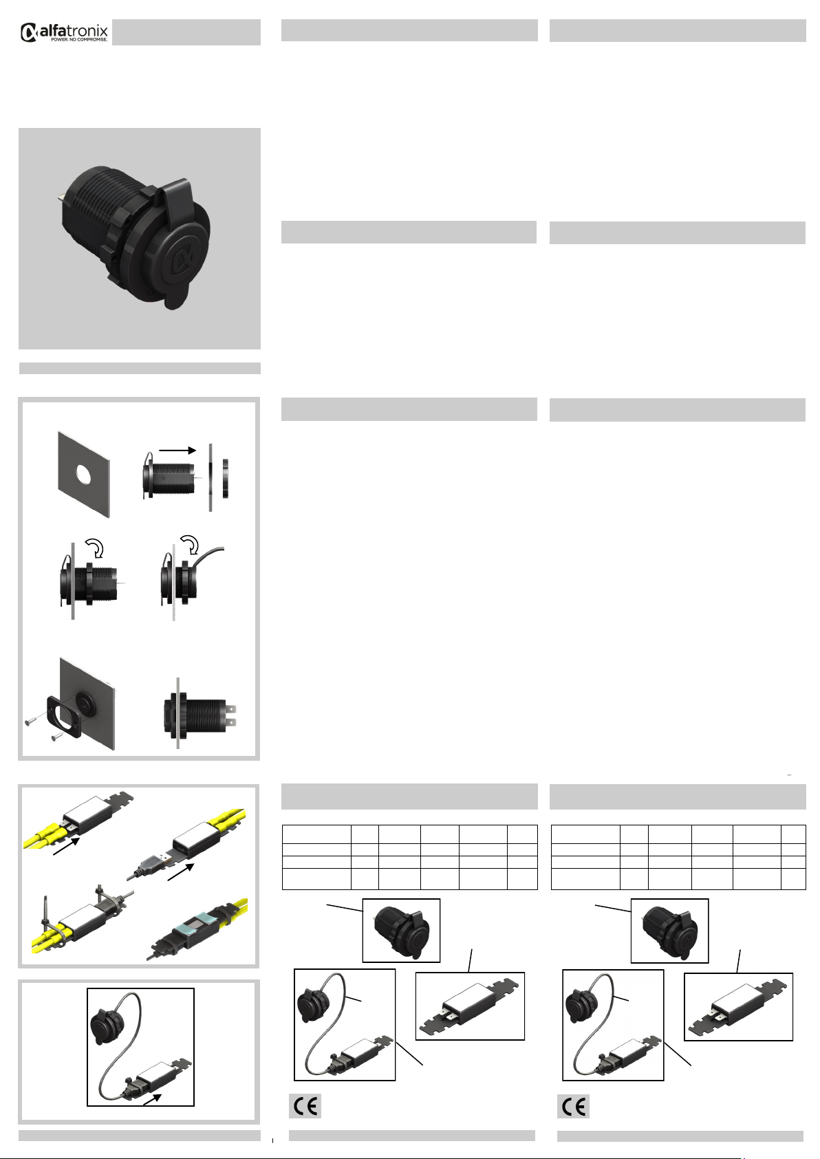
MONTAGE (PV USB-1 and PV USB Socket)
1. Trennen Sie den Stromkreis bevor Sie das Gerät anschließen oder wieder ent-
fernen.
2. Wählen Sie eine geeignete Montagefläche und stellen Sie sicher dass nichts
dahinter beschädigt werden kann bevor Sie ein Ø30mm Loch bohren.
3. Entfernen Sie die Mutter vom Spannungswandler und setzen Sie diesen in das
Loch.
4. Verschrauben Sie die Mutter auf der Rückseite des Gehäuses und stellen Sie sicher
dass die Vorderseite rechtwinklig ist.
5. Sollte die Mutter aus Zugangsgründen nicht rückseitig installiert werden können,
kann die Planscheibe mit den mitgelieferten Schrauben zum befestigen des
Gehäuses benutzt werden.
6. Verbinden Sie den positiven Eingang mit der Klemme die mit + gekennzeichnet ist ,
Verbinden Sie den negative Eingang mit der Klemme die mit –gekennzeichnet ist.
MONTAGE (PV USB-2)
1. Trennen Sie den Stromkreis bevor Sie das Gerät anschließen oder wieder ent-
fernen.
2. Verbinden Sie den positiven Eingang mit der Klemme die mit + gekennzeichnet ist ,
Verbinden Sie den negative Eingang mit der Klemme die mit –gekennzeichnet ist.
3. Stecken Sie den USB Stecker in die USB Buchse ( diese wird schwergängiger als
Standard USB Buchsen sein um den Stecker in Position zu halten).
4. Sichern Sie alle Kabel mit Kabelbindern.
5. Sichern Sie das Gerät entweder mit Kabelbindern oder Doppelklebepads
(mitgeliefert).
MONTAGE (PV USB-3)
1. Installieren Sie die ‘PV USB Socket’ wie oben.
2. Stecken Sie den Stecker der ‘PV USB Socket’ in die Buchse des ‘PV USB-2’.
3. Installieren Sie die ‘USB PV USB-2’ wie oben.
29 Newtown Business Park, Poole, BH12 3LL, UK • www.alfatronix.com
Dieses Gerät ist in Erfüllung der EU Direktive 2004/108/EC. Das
Typenschild befindet sich auf der Oberseite des Gerätes.
SICHERHEIT
DEUTSCH
Artikel Leistung Eingang
Spannung Größe Gewicht
Ausgang
Spannung
PV USB-1 2.1A 9-32Vdc Ø37x58mm 33g5Vdc
PV USB-2 2.1A 9-32Vdc 113x24x15mm 30g*5Vdc
PV USB-3
(PV USB-2 & PV USB Socket) 2.1A 9-32Vdc 5Vdc 113x24x15mm
/Ø37x31mm 60g*
MONTAGE
vB
TECHNISCHE DATEN
SICHERHEIT
 Das Gerät darf nicht extremen mechanischen Schocks, extremen Temperaturen,
direkter Sonneneinstrahlung oder starken Vibrationen ausgesetzt werden und soll nur
in einer trockenen Umgebung installiert werden wie zum Beispiel ein Fahrzeug
 Das Gerät nicht auf heißen Fahrzeugteilen installieren und genügend Platz für Luft
Zirkulation und Kühlung gewährleistet.
 Den Kabelbaum durch Sicherungen schützen.
 Die Stärke und Polarität des Ausgangs sollte bei der Installation beobachtet werden.
Inkorrekte Polarität am Ausgang könnte den Schaltkreis beschädigen.
 Den Schaltkreis isolieren bevor das Gerät ein–oder abmontiert wird.
 Sollte das Gerät defekt sein muss es ausgetauscht werden. Das öffnen des Gehäuses
oder die Reparatur des defekten Gerätes ist untersagt.
SICHERUNGEN
Der Eingang an der Verkabelung muss durch Sicherungen adäquat geschützt warden.
PV USB-1
PV USB-2
PV USB-3
INHALT
PV-USB1
 1 x PowerVerter USB-1 2 x Schrauben
 2 x Flachsteckverbindungen 1 x Planscheibe
PV-USB2
 1 x PowerVerter USB-2 4 x Kabelbinder
 2 x Flachsteckverbindungen 2 x Klebepads
PV-USB3
 1 x PowerVerter USB-2 2 x Schrauben
 1 x PowerVerter USB Socket 1 x Planscheibe
 2 x Flachsteckverbindungen 2 x Klebepads
 4 x Kabelbinder
INHALT
1,2
+
-
3
4 5
PV USB-2
PV USB-3
PV USB-1 & PV USB Socket
INFORMACIÓN
VOLUMEN DE SUMINISTRO
 Compatible con sistemas de 12V y 24V
 Tensión de salida de 5 V CC
 Autodetección de Apple y Android
 Suministrado con terminales FASTON
ENSAMBLAJE (PV USB-1 and PV USB Socket)
1. Aislar el circuito antes de conectar o desconectar el dispositivo.
2. Escoger una superficie de montaje adecuada y asegurar que no pueda
dañarse nada detrás, después hacer un orificio de Ø30mm.
3. Quitar la tuerca del cuerpo del convertidor e introducir la estructura por el
orificio.
4. Apretar la tuerca en la parte de atrás de la estructura asegurando que la
parte delantera queda en ángulo recto.
5. Si no se puede apretar la tuerca por no tener mucho acceso por detrás, se
puede utilizar la placa delantera para sujetar la estructura en su sitio con
los tornillos suministrados.
6. Conectar la entrada positiva al terminal +, y la negativa al terminal –.
ENSAMBLAJE (PV USB-2)
1. Aislar el circuito antes de conectar o desconectar el dispositivo.
2. Conectar la entrada positiva al terminal +, y la negativa al terminal –.
3. Introducir el conector USB en el receptor USB (será más duro que un
receptor USB normal para que no se mueva).
4. Asegurar todos los cables y amarres.
5. Asegurar la unidad con los amarres o con las pegatinas dobles
(suministradas).
ENSAMBLAJE (PV USB-3)
1. Instalar el receptor `PV USB Socket’ se indica.
2. Introducir el enchufe del ‘PV USB Socket’ en el receptor ‘PV USB-2’.
3. Instalar el receptor ‘PV USB-2’ se indica.
Este aparato cumple los requisites prescritos en la directive de la UE
2004/108/CE. La placa de identificación se encuentra en la parte
superior del aparato.
SEGURIDAD
ESPAÑOL
ENSAMBLAJE
DATOS TÉCNICOS
SEGERIDAD
 El aparato no debe quedar expuesto a fuertes sacudidas mecánicas.
 El aparato no debe quedar expuesto a temperaturas extremas ni a una radiación
directa del sol ni a intensas vibraciones.
 El aparato sólo se puede poner en funcionamiento en un entorno seco, es decir, en el
interior del vehículo.
 No lo instale en partes calientes del vehículo y preste atención a que haya suficiente
espacio libre alrededor del aparato para permitir la circulación de aire y, con ello, la
refrigeración
 Proteger las conexiones con fusibles
 Durante el montaje preste atención a la altura y la polaridad de la tensión de salida.
Una polaridad incorrecta o sobretensión pueden perjudicar el circuito de corriente
 Cortar la corriente antes de conectar el aparato o de desmontarlo
 No está permitido abrir ni reparar el aparato. En caso de avería, deberá cambiarse.
FUSING
Los cables de entrada han de conectarse a los fusibles adecuadamente.
PV USB-1
PV USB-2
PV USB-3
VOLUMEN DE SUMINISTRO
PV-USB1
 1 x PowerVerter USB-1 2 x Tornillos
 2 x Terminales de Crimpar 1 x Placa delantera
PV-USB2
 1 x PowerVerter USB-2 4 x Brida
 2 x Terminales de Crimpar 2 x Pegatinas
PV-USB3
 1 x PowerVerter USB-2 2 x Tornillos
 1 x PowerVerter USB Socket 1 x Placa delantera
 2 x Terminales de Crimpar 2 x Pegatinas
 4 x Brida
VOLUMEN DE SUMINISTRO
Número de pieza Potencia Entrada
Voltaje Dimensiones Peso
Salida
Voltaje
PV USB-1 2.1A 9-32Vdc Ø37x58mm 33g5Vdc
PV USB-2 2.1A 9-32Vdc 113x24x15mm 30g*5Vdc
PV USB-3
(PV USB-2 & PV USB Socket) 2.1A 9-32Vdc 5Vdc 113x24x15mm
/Ø37x31mm 60g*
6
+
-
3
5
1,2
4
250mm 250mm

This manual suits for next models

2

Other alfatronix Power Supply manuals

alfatronix PV-USB1 Manual

alfatronix

alfatronix PV-USB1 Manual

alfatronix PowerTector PT10 Manual

alfatronix

alfatronix PowerTector PT10 Manual

alfatronix PVPro-S/A Manual

alfatronix

alfatronix PVPro-S/A Manual

alfatronix A/C.PVPro-S Manual

alfatronix

alfatronix A/C.PVPro-S Manual

alfatronix PowerTector PT40 Manual

alfatronix

alfatronix PowerTector PT40 Manual

alfatronix AD Series Manual

alfatronix

alfatronix AD Series Manual

alfatronix PR65R Manual

alfatronix

alfatronix PR65R Manual

Popular Power Supply manuals by other brands

Lütze CPS2B1-120-24 instruction manual

Lütze

Lütze CPS2B1-120-24 instruction manual

Nice PS 224 Instructions and warnings for the fitter

Nice

Nice PS 224 Instructions and warnings for the fitter

Zippy Tech. HG2 user manual

Zippy Tech.

Zippy Tech. HG2 user manual

Delta Elektronika SM 15-400 product manual

Delta Elektronika

Delta Elektronika SM 15-400 product manual

Chauvet EPIX Flex Drive user manual

Chauvet

Chauvet EPIX Flex Drive user manual

Solcon RVS-AX Instruction and Commissioning Manual

Solcon

Solcon RVS-AX Instruction and Commissioning Manual

SilverStone GEMINI GM600-G manual

SilverStone

SilverStone GEMINI GM600-G manual

3Com 3644A user manual

3Com

3Com 3644A user manual

Akyga AK-PD-03 user manual

Akyga

Akyga AK-PD-03 user manual

NESpace NESPACE 48/3K Maintenance & Operation Manual

NESpace

NESpace NESPACE 48/3K Maintenance & Operation Manual

Joy-it JT-RD6012-C manual

Joy-it

Joy-it JT-RD6012-C manual

Aiphone IS-PU-S PRECAUTION & MOUNTING INSTRUCTION SHEET

Aiphone

Aiphone IS-PU-S PRECAUTION & MOUNTING INSTRUCTION SHEET

puls miniline ML90.200 instruction manual

puls miniline

puls miniline ML90.200 instruction manual

Cosel PLA30F instruction manual

Cosel

Cosel PLA30F instruction manual

PPA SS 400 CR manual

PPA

PPA SS 400 CR manual

BCP PUOU1CSV How to install

BCP

BCP PUOU1CSV How to install

Good Will Instrument PSM-3004 user manual

Good Will Instrument

Good Will Instrument PSM-3004 user manual

BCP PUOOUCWWH How to install

BCP

BCP PUOOUCWWH How to install

manuals.online logo
manuals.online logoBrands
  • About & Mission
  • Contact us
  • Privacy Policy
  • Terms and Conditions

Copyright 2025 Manuals.Online. All Rights Reserved.