HBD PV500-0007M1 User manual

PV500 Series solar pump Inverter
User's manual
Ver:2.00


PV500 series solar pumping inverters
Contents
-1-
Contents
Contents........................................................................................................................................................ 1
1 Safety precautions................................................................................................................................2
1.1 Safety definition............................................................................................................................2
1.2 Warning symbols..........................................................................................................................2
1.3 Safety guidelines.......................................................................................................................... 3
2 Product overview.................................................................................................................................. 5
2.1 Unpacking inspection.................................................................................................................. 5
2.2 Name plate....................................................................................................................................5
2.3 Type designation key................................................................................................................... 5
2.4 Product specifications..................................................................................................................6
2.5 Rated specifications.....................................................................................................................7
3 Installation guidelines.........................................................................................................................12
3.1 Mechanical installation.............................................................................................................. 12
3.2 Standard wiring.......................................................................................................................... 14
4 Keypad operation procedure.............................................................................................................20
4.1 Keypad introduction................................................................................................................... 20
4.2 Keypad operation.......................................................................................................................22
5 Commissioning guidelines.................................................................................................................24
5.1 Inspection before operation...................................................................................................... 24
5.2 Trial run....................................................................................................................................... 24
5.3 Parameter settings.....................................................................................................................24
5.4 Advanced settings......................................................................................................................24
6 Function parameters.......................................................................................................................... 26
6.1 Common function parameters for solar pumping inverter control........................................26
6.2 Parameters of special functions...............................................................................................45
7 Fault diagnosis and solution............................................................................................................. 62
Appendix E Further information................................................................................................................ 68
E.1 Product and service inquiries................................................................................................... 68
E.2 Feedback of OUR Inverters manuals...................................................................................... 68
E.3 Document library on the Internet..............................................................................................68
PV500 series solar pumping inverters
Safety precautions
-2-
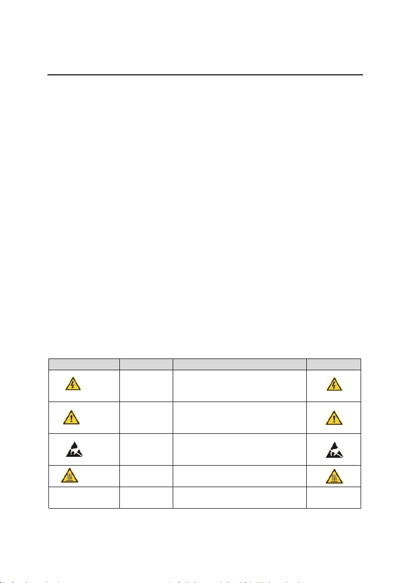
Symbols
Name
Instruction
Abbreviation
Danger
Danger
Serious physical injury or even
death may occur if not follow the
relative requirements
Warning
Warning
Physical injury or damage to the
devices may occur if not follow the
relative requirements
Do not
Electrostatic
discharge
Damage to the PCBA board may
occur if not follow the relative
requirements
Hot sides
Hot sides
Sides of the device may become
hot. Do not touch.
Note
Note
Physical hurt may occur if not follow
the relative requirements
Note
1 Safety precautions
Please read this manual carefully and follow all safety precautions before moving, installing,
operating and servicing the inverter. If ignored, physical injury or death may occur, or damage
may occur to the devices.
If any physical injury or death or damage to the devices occurs for ignoring to the safety
precautions in the manual, our company will not be responsible for any damages and we are
not legally bound in any manner.
1.1 Safety definition
Danger:
Serious physical injury or even death may occur if not follow
relevant requirements
Warning:
Physical injury or damage to the devices may occur if not follow
relevant requirements
Note:
Physical hurt may occur if not follow relevant requirements
Qualified
electricians:
People working on the device should take part in professional
electrical and safety training, receive the certification and be
familiar with all steps and requirements of installing,
commissioning, operating and maintaining the device to avoid
any emergency.
1.2 Warning symbols
Warnings caution you about conditions which can result in serious injury or death and/or
damage to the equipment, and advice on how to avoid the danger. Following warning symbols
are used in this manual:

PV500 series solar pumping inverters
Safety precautions
-3-
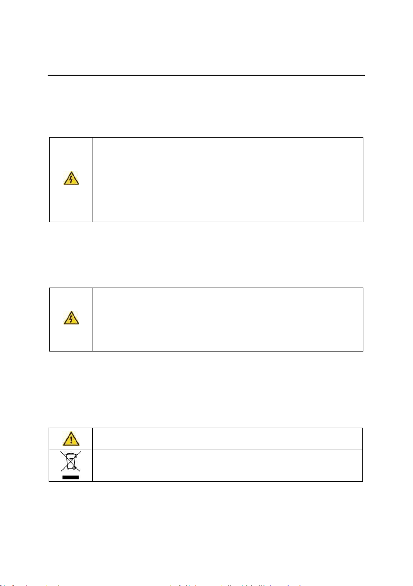
1.3 Safety guidelines
● Only qualified electricians are allowed to operate on the inverter.
● Do not carry out any wiring and inspection or changing components when
the power supply is applied. Ensure all input power supply is disconnected
before wiring and checking and always wait for at least the time designated
on the inverter or until the DC bus voltage is less than 36V. Below is the
table of the waiting time:
Inverter model
Minimum waiting time
1PH 220V
0.4kW-2.2kW
5 minutes
3PH 220V
4kW-7.5kW
5 minutes
3PH 380V
0.75kW-37kW
5 minutes
● Do not refit the inverter unauthorized; otherwise fire, electric shock or other
injury may occur.
● The base of the radiator may become hot during running. Do not touch to
avoid hurt.
● The electrical parts and components inside the inverter are electrostatic.
Take measurements to avoid electrostatic discharge during relevant
operation.
1.3.1
Delivery and installation
● Please install the inverter on fire-retardant material and keep the inverter
away from combustible materials.
● Do not operate on the inverter if there is any damage or components loss
to the inverter.
● Do not touch the inverter with wet items or body, otherwise electric shock
may occur.
Note:
● Select appropriate moving and installing tools to ensure a safe and normal running of
the inverter and avoid physical injury or death. For physical safety, the erector should
take some mechanical protective measurements, such as wearing safety shoes and
working uniforms.
● Do not carry the inverter by its cover. The cover may fall off.
● Ensure to avoid physical shock or vibration during delivery and installation.
● Install away from children and other public places.
● The inverter cannot meet the requirements of low voltage protection in IEC61800-5-1 if
the altitude of installation site is above 2000m.
● The leakage current of the inverter may be above 3.5mA during operation. Ground with
proper techniques and ensure the grounding resistor is less than 10Ω. The conductivity
of PE grounding conductor is the same as that of the phase conductor (with the same
cross sectional area).
PV500 series solar pumping inverters
Safety precautions
-4-
● (+) and (-) are DC power supply input terminals. R, S and T (L,N) are AC power supply
input terminals. U, V and W are output terminals. Please connect the input power
cables and motor cables with proper techniques; otherwise the damage to the inverter
may occur.
1.3.2
Commissioning and running
●Disconnect all power supplies applied to the inverter before the terminal
wiring and wait for at least the designated time after disconnecting the
power supply.
●High voltage is present inside the inverter during running. Do not carry out
any operation except for the keypad setting.
●The inverter cannot be used as “Emergency-stop device”.
If the inverter is used to break the motor suddenly, a mechanical braking
device should be provided.
Note:
● Do not switch on or off the input power supply of the inverter frequently.
● For inverters that have been stored for a long time, check and fix the capacitance and
try to run it again before utilization.
● Cover the front board before running, otherwise electric shock may occur.
1.3.3
Maintenance and replacement of components
● Only qualified electricians are allowed to perform the maintenance,
inspection, and components replacement of the inverter.
● Disconnect all power supplies to the inverter before the terminal wiring.
Wait for at least the time designated on the inverter after disconnection.
●Take measures to avoid screws, cables and other conductive materials to
fall into the inverter during maintenance and component replacement.
Note:
● Please select proper torque to tighten screws.
● Keep the inverter, parts and components away from combustible materials during
maintenance and component replacement.
● Do not carry out any isolation voltage-endurance test on the inverter and do not
measure the control circuit of the inverter by megameter.
1.3.4
Scrap treatment
●
There are heavy metals in the inverter. Deal with it as industrial
effluent.
●
When the life cycle ends, the product should enter the recycling
system. Dispose of it separately at an appropriate collection point
instead of placing it in the normal waste stream.
PV500 series solar pumping inverters
Product overview
-5-
2 Product overview
2.1 Unpacking inspection
Check as follows after receiving products:
1. Check that there are no damage and humidification to the package. If not, please
contact with local agents or Our offices.
2. Check the information on the type designation label on the outside of the package to
verify that the drive is of the correct type. If not, please contact with local dealers or Our
offices.
3. Check that there are no signs of water in the package and no signs of damage or breach
to the inverter. If not, please contact with local dealers or Our offices.
4. Check the information on the type designation label on the outside of the package to
verify that the name plate is of the correct type. If not, please contact with local dealers or
Our offices.
5. Check to ensure the accessories (including user’s manual and control keypad) inside
the device is complete. If not, please contact with local dealers or Our offices.
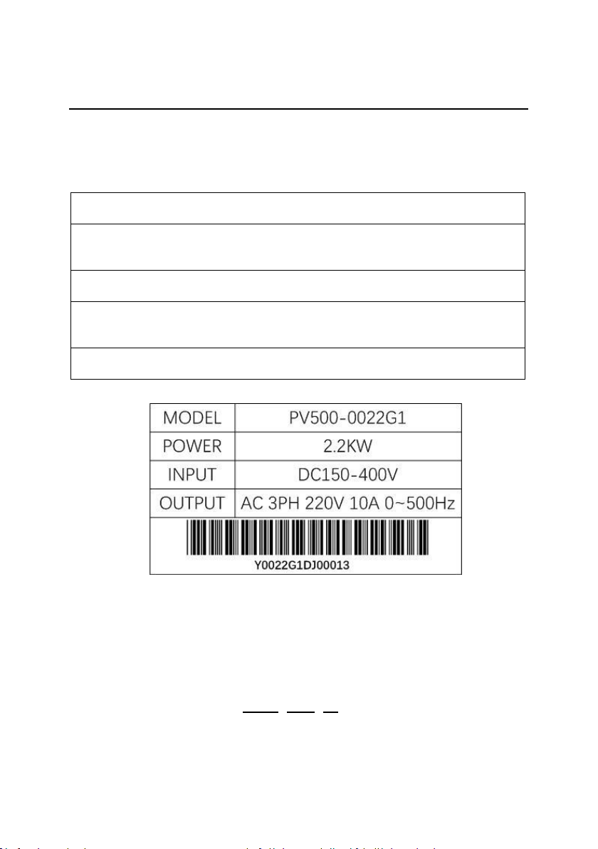
2.2 Name plate
Figure 2-1 Name plate
Note: This is the example of PV500 standard products and the CE\TUV\IP20 certifications are
marked according to the reality.
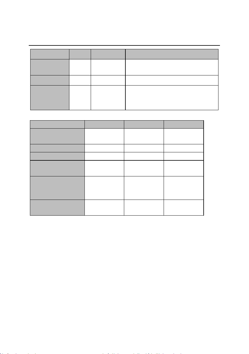
2.3 Type designation key
The type designation contains information on the inverter. The user can find the type
designation on the type designation label attached to the inverter or the simple name plate.
PV500 – 0055 – G1
① ② ③
PV500 series solar pumping inverters
Product overview
-6-
Key
Sign
Description
Remarks
Product
abbreviation
①
Product
abbreviation
PV500 Series.
Rated power
②
Power range
0.75—55kW
Voltage
degree
③
Voltage
degree
G1: AC 1PH 220V(-15%)~240(+10%)
G2: AC 3PH 220V(-15%)~240(+10%)
G3: AC 3PH 380V(-15%)~440(+10%)
2.4 Product specifications
Model
G1
G2
G3
AC input voltage (V)
220(-15%)~240
(+10%) (1PH)
220(-15%)~240
(+10%) (3PH)
380(-15%)~440
(+10%) (3PH)
Max. DC voltage (V)
400
400
800
Start-up voltage (V)
200
200
300
Lowest working
voltage (V)
150
150
250
Recommended DC
input voltage range
(V)
200~400
200~400
300~750
Recommended MPP
voltage (V)
330
330
550
PV500 series solar pumping inverters
Product overview
-7-
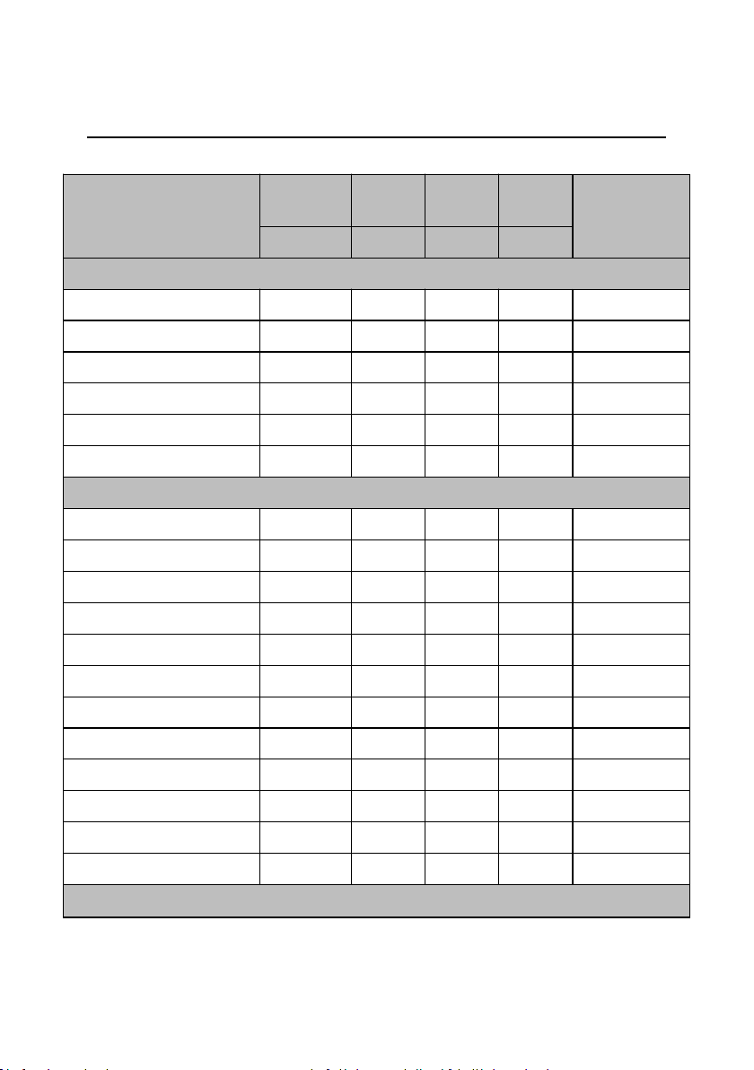
2.5 Rated specifications
Type
Drive
motor
Power
capacity
Input
current
Output
current
Shape case
kW
kVA
A
A
Single-phase power supply: 220V, 50/60Hz
PV500-0004M1
0.4
0.5
5.4
2.5
000
PV500-0007M1
0.75
1
8.2
4
000
PV500-0015M1
1.5
2
14
7
000
PV500-0007G1
0.75
1
4.2
4
001
PV500-0015G1
1.5
2
14
7
001
PV500-0022G1
2.2
3
23
10
001
Three -phase power supply: 220V, 50/60Hz
PV500-0040G2
4
5
18.1
16
002
PV500-0055G2
5.5
7.5
28
25
003
PV500-0075G2
7.5
10
37.1
32
003
PV500-0110G2
11
15
49.8
45
004
PV500-0150G2
15
20
65.4
60
004
PV500-0185G2
18.5
25
81.6
75
004
PV500-0220G2
22
30
97.7
90
005
PV500-0300G2
30
40
122.1
110
005
PV500-0370G2
37
50
157
150
006
PV500-0450G2
45
60
185
170
006
PV500-0550G2
55
70
215
210
007
PV500-0750G2
75
100
320
300
007
Input specification

PV500 series solar pumping inverters
Product overview
-8-
PV Input
Maximum Input DC Voltage
400VDC
Recommended MPPT Voltage
Range
250~350VDC
Recommended Input Operation
Voltage
310VDC
Grid or backup generator input
Input voltage
Single phase 220V(-15%~30%)
Output specification
Rated output voltage
3PH 220V
Output frequency
0~500.00Hz(default: 0~50.00Hz)
Protection
Built-in Protection
Lighting Protection, over-current, overvoltage, output phase-
lose, under-load, under-voltage, short circuit, overheating,
water pump run dry etc.
PV500 series solar pumping inverters
Product overview
-9-
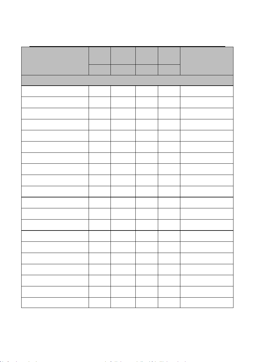
Type
Drive
motor
Power
capacity
Input
current
Output
current
Shape case
kW
kVA
A
A
Three-phase power supply: 380V, 50/60Hz
PV500-0007G3
0.75
1
3.4
2.1
001
PV500-0015G3
1.5
2
5
3.8
001
PV500-0022G3
2.2
3
5.8
5
001
PV500-0040G3
4
5
10.5
9
002
PV500-0055G3
5.5
7.5
14.6
13
002
PV500-0075G3
7.5
10
20.5
17
002
PV500-0110G3
11
15
26
25
003
PV500-0150G3
15
20
35
32
003
PV500-0185G3
18.5
25
38.5
38
003
PV500-0220G3
22
30
46.5
45
004
PV500-0300G3
30
40
62
60
004
PV500-0370G3
37
50
76
75
004
PV500-0450G3
45
60
92
90
005
PV500-0550G3
55
70
113
110
005
PV500-0750G3
75
100
157
150
006
PV500-0930G3
93
125
180
170
006
PV500-1100G3
110
150
214
210
007
PV500-1320G3
132
175
256
250
007
PV500-1600G3
160
210
307
300
007
PV500-1850G3
185
250
385
340
008
PV500 series solar pumping inverters
Product overview
-10-
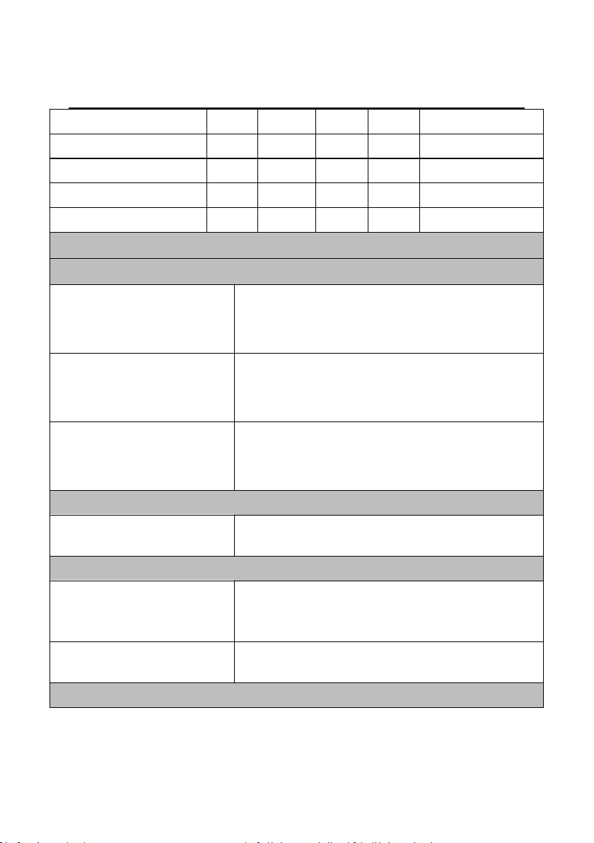
PV500-2000G3
200
260
385
380
008
PV500-2200G3
220
300
430
415
008
PV500-2500G3
250
350
468
470
008
PV500-2800G3
280
370
525
520
008
PV500-3150G3
315
400
590
585
009
Input specification
PV Input
Maximum Input DC Voltage
800VDC
Recommended MPPT Voltage
Range
450~600VDC
Recommended Input Operation
Voltage
540VDC
Grid or backup generator input
Input Voltage
Three phase 380V(-15%~30%)
Output specification
Rated output voltage
3PH 380V
Output frequency
0~500.00Hz(Default 0~50.00Hz)
Protection
PV500 series solar pumping inverters
Product overview
-11-
Built-in Protection
Lighting Protection, over-current, overvoltage, output phase-
lose, under-load, under-voltage, short circuit, overheating,
water pump run dry etc.
General Parameters
Application Site
No direct sunshine, no dust、corrosive gas、combustible
gas、oil mist、steam、dripping or salinity etc.
Altitude
0~2000 m
Derated use above 1000m,per 100m, the rated output
current decrease 1%.
Environment Temperature
-10℃~40℃(Environment Temperature be 40℃~50℃,
please keep derated use.)
Humidity
5~95%,non-condensation
Vibration
less than 5.9 m/s2(0.6g)
Storage Temperature
-20℃~+70℃
Efficiency
Rated Power Run≥93%
Installation
Wall or rail mounting
Protection Grade
IP20
Cooling
Forced Air Cooling

PV500 series solar pumping inverters
Installation guidelines
-12-
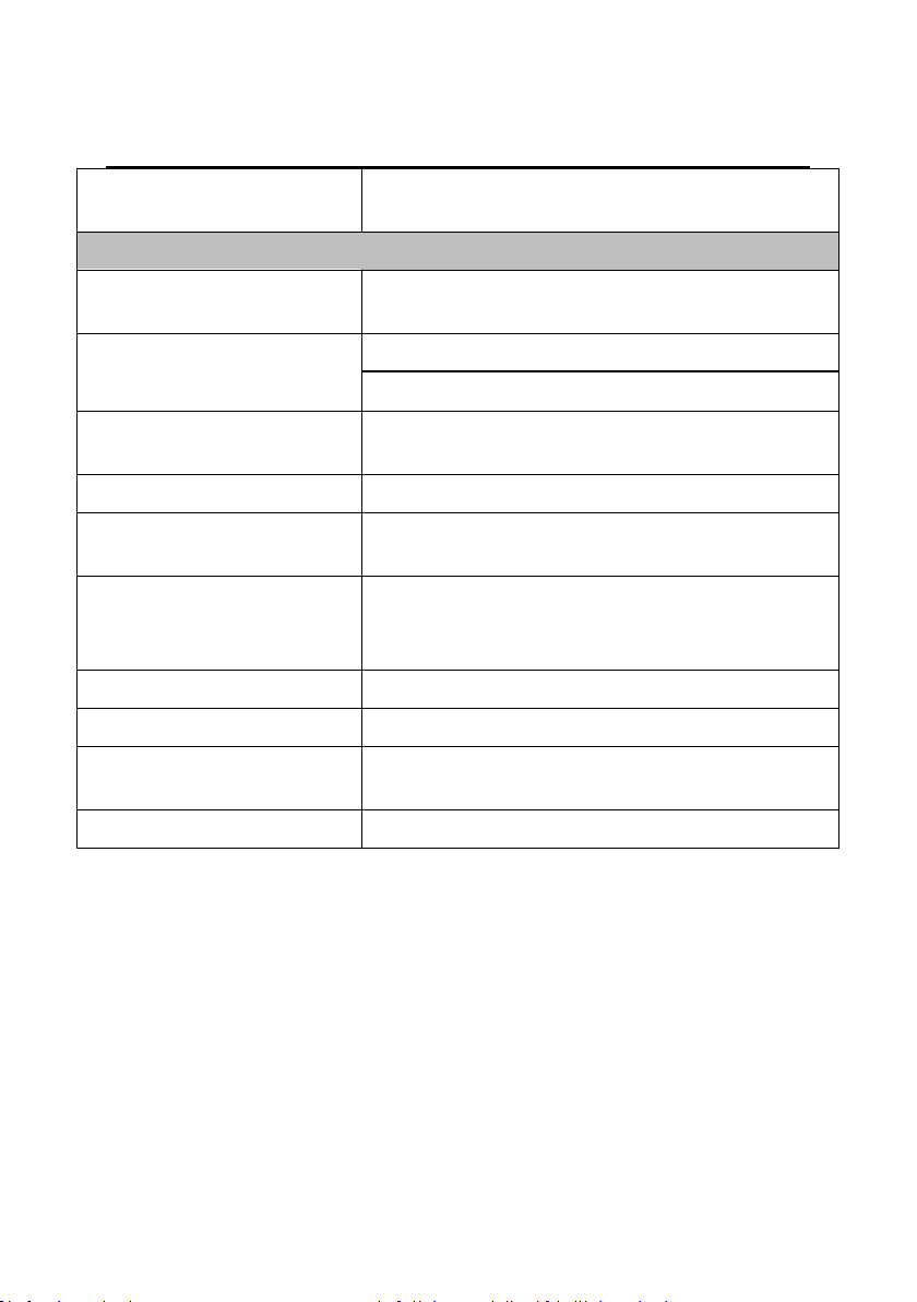
Environment
Conditions
Installation site
Indoor
Environment
temperature
The ambient temperature of inverter is -10℃~50℃while air
temperature change should be less than 0.5℃per minute.
The inverter will be derated once ambient temperature exceeds 40℃. It
is not recommended to use the inverter if ambient temperature is above
50℃.
To ensure reliability, do not use the inverter if the ambient temperature
changes frequently.
Provide cooling fan or air conditioner to control the internal ambient
temperature below the required one if the inverter is used in a close
space such as in the control cabinet.
When the temperature is too low, if the inverter needs to restart to run
after a long stop, it is necessary to provide an external heating device to
increase the internal temperature, otherwise damage to the devices may
occur.
Humidity
RH≤90%. No condensation is allowed.
Storage
temperature
-40°C~+70°C. The temperature change rate is less than 1°C/minute.
3 Installation guidelines
The chapter describes the mechanical installation and electric installation.
● Only qualified electricians are allowed to carry out what described in this
chapter. Please operate as the instructions in Safety precautions.
Ignoring these may cause physical injury or death or damage to the
devices.
● Ensure the power supply of the inverter is disconnected during the
operation. Wait for at least the time designated after the disconnection if
the power supply is applied.
● The installation and design of the inverter should be complied with the
requirement of the local laws and regulations in the installation site. If the
installation infringes the requirement, our company will exempt from any
responsibility. Additionally, if users do not comply with the suggestion,
some damage beyond the assured maintenance range may occur.
3.1 Mechanical installation
3.1.1
Installation environment
The installation environment is the safeguard for a full performance and long-term stable
functions of the inverter. Check the installation environment as follows:
PV500 series solar pumping inverters
Installation guidelines
-13-
Environment
Conditions
Running
environment
condition
The installation site of the inverter should:
Keep away from the electromagnetic radiation source;
Keep away from contaminative air, such as corrosive gas, oil mist and
flammable gas;
Ensure foreign objects, such as metal power, dust, oil, water cannot
enter into the inverter(do not install the inverter on the flammable
materials such as wood);
Keep away from direct sunlight, oil mist, steam and vibration
environment.
Pollution
Pollution degree 2
Altitude
Below 1000m
If the altitude is above 1000m, please derate 1% for every additional
100m.
Vibration
≤ 5.8m/s2(0.6g)
Installation
direction
The inverter should be installed on an upright position to ensure
sufficient cooling effect.
Note:
PV500 series inverters should be installed in a clean and ventilated environment
according to enclosure classification.
Cooling air must be clean, free from corrosive materials and electrically conductive dust.
3.1.2
Installation direction
The inverter may be installed on the wall or in a cabinet.
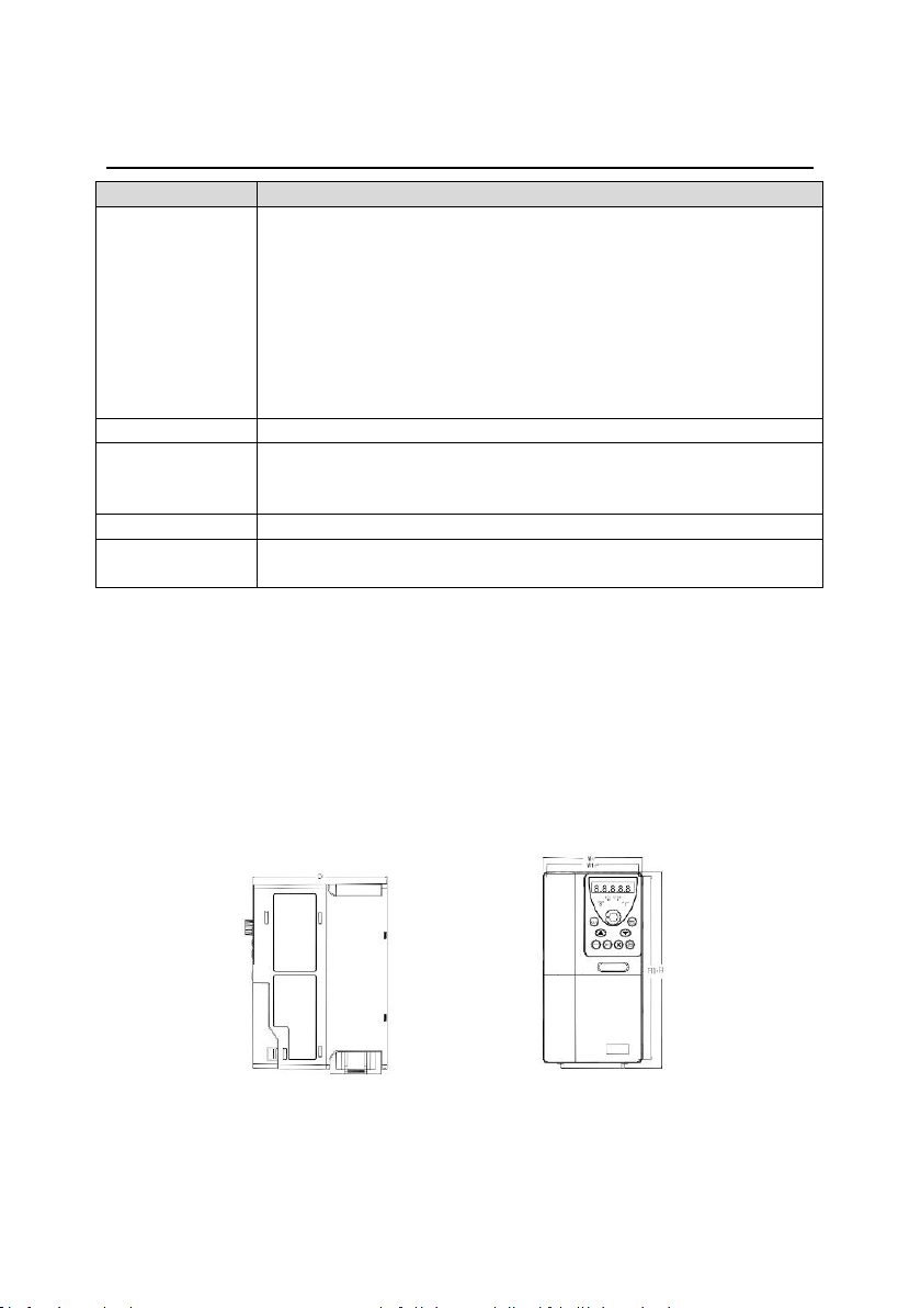
The inverter needs be installed in the vertical position. Check the installation site according to
the requirements below. See Appendix D Dimension drawings for frame details.
3.1.3
Installation manner
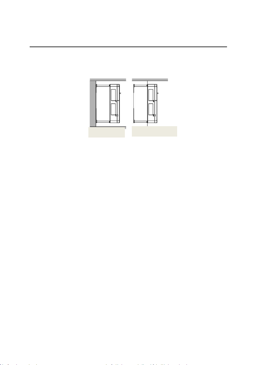
(1)
The inverters ≤ 2.2kW support wall mounting and rail mounting.
a)
Wall mounting b) Rail mounting
PV500 series solar pumping inverters
Installation guidelines
-14-
Figure 3-1 Installation manners
Note: The minimum space of A and B is 100mm. H is 36.6mm and W is 35.0mm.
(2)
The inverters ≥ 4kW support wall mounting and flange mounting.
Wall mounting Flange installation
Figure 3-2 installation manners
1)
Mark the locations of installation holes. For details about the holes, see the inverter
dimension diagram in the appendix.
2)
Fix the screws or bolts into the marked locations.
3)
Lean the inverter against the wall.
4)
Fasten the tightening screws on the wall.
3.2 Standard wiring
3.2.1
Terminals of main circuit
The figure below shows the standard wiring of inverter.

PV500 series solar pumping inverters
Installation guidelines
-15-
Figure 3-3 Standard wiring diagram
● The DC breaker Q1 must be installed as the protection switch for PV input.
● In parallel connection, the combination box special for PV must be used.
● When the distance between the PV input component and inverter exceeds
10 meters, type-II surge protection devices must be configured at the DC
side.
● When the distance between the pump and inverter exceeds 50 meters, it is
recommended to configure output reactors. See appendix A.4 for the
output reactor model selection.
● The inverter automatically runs after being powered on. If parameters need
to be set, follow the parameter setting instructions in chapter 5.
● Before connecting the braking resistor cable, remove the yellow labels of
PB, (+), and (-) from the terminal blocks. Otherwise, poor connection may
occur.
PV500 series solar pumping inverters
Installation guidelines
-16-
Terminals of main circuit
Terminal
Name
Function
R, S, T
(L, N)
AC input
3PH (1PH) AC input terminals, connected to the grid
Note: Use the screws equipped with the inverter for
wiring.
(+), (-)
PV input
Solar cell panel input terminals
U, V, W
Inverter
output
3PH/1PH AC output terminals, connected to the pump
motor
Note: 1PH motors must connect to terminals U and W.
Safety
grounding
Safety protection grounding terminal. Each inverter
must be grounded
Description for G1 single-phase output models
1)
Generally, the output terminals U and W of the inverter connect to the phase cables of the
single-phase motor.
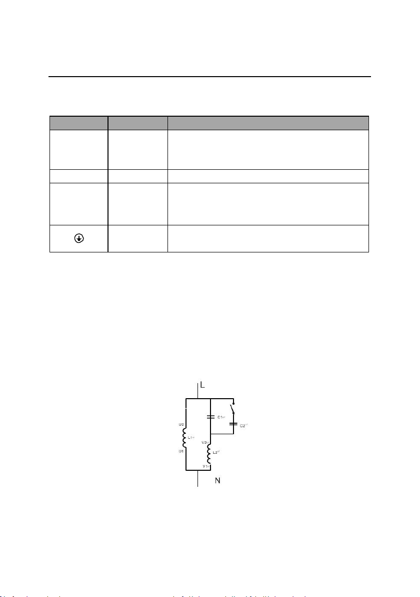
2)
If the single-phase pump cannot be started, the two-phase control method must be used,
and the start-up and running capacitors (if any) of the motor must be removed. The figure
below shows the internal wiring of the common single-phase motor. In the figure, L1, L2, C1,
and C2 indicate the running winding, start-up winding, running capacitor, and start-up
capacitor. When the motor speed exceeds 75% of the rated speed, the start-up capacitor is
switched off.
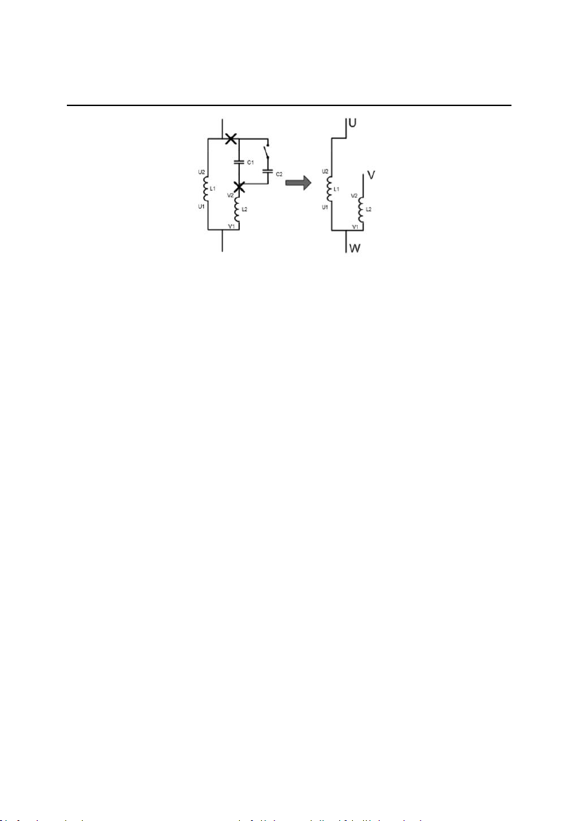
Internal wiring of the single-phase motor winding after removing the starting and running
capacitor:
PV500 series solar pumping inverters
Installation guidelines
-17-
U1 and V1 are the common terminals of the windings. Connect them to the output terminal W
of the solar pumping inverter. Connect U2 to the output terminal U of the inverter. Connect V2
to the output terminal V of the inverter. (Note: Use the screws equipped with the inverter.)
Connect DI4 of the inverter to COM in short circuited manner.
PV500 series solar pumping inverters
Installation guidelines
-18-
3.2.2
Terminals of control circuit
Functions of control terminals
Category
Terminal
symbol
Terminal name
Terminal function
Power supply
24V
24V power supply
It provides the power of
24V±10% and maximum current
of 200mA.
It functions as the working power
supply of digital input and output
or externally connects to the
sensor power supply.
COM
Common terminal
Digital input
DI1
Forced switch to
power frequency
Terminal feature parameters:
1.
Internal impedance: 3.3kΩ
2.
Acceptable voltage input:
12~24V
3.
Maximum input frequency:
1kHz
DI1: Forcible switch to power
frequency (Switching-on indicates
switching to power frequency, and
switching-off indicates input
controlled by the keypad.)
DI2: It connects to the high-
water switch of the normally
open contact by default.
DI3: It connects to the low-water
switch of the normally closed
contact.
DI4: A high electrical level
corresponds to the single-phase
algorithm. A low electrical level
corresponds to the two-phase
algorithm.
DI2
Full-water alarm
DI3
Empty-water
alarm
DI4
Single/two phase
algorithm
switching
This manual suits for next models
18
Table of contents
Other HBD Inverter manuals


