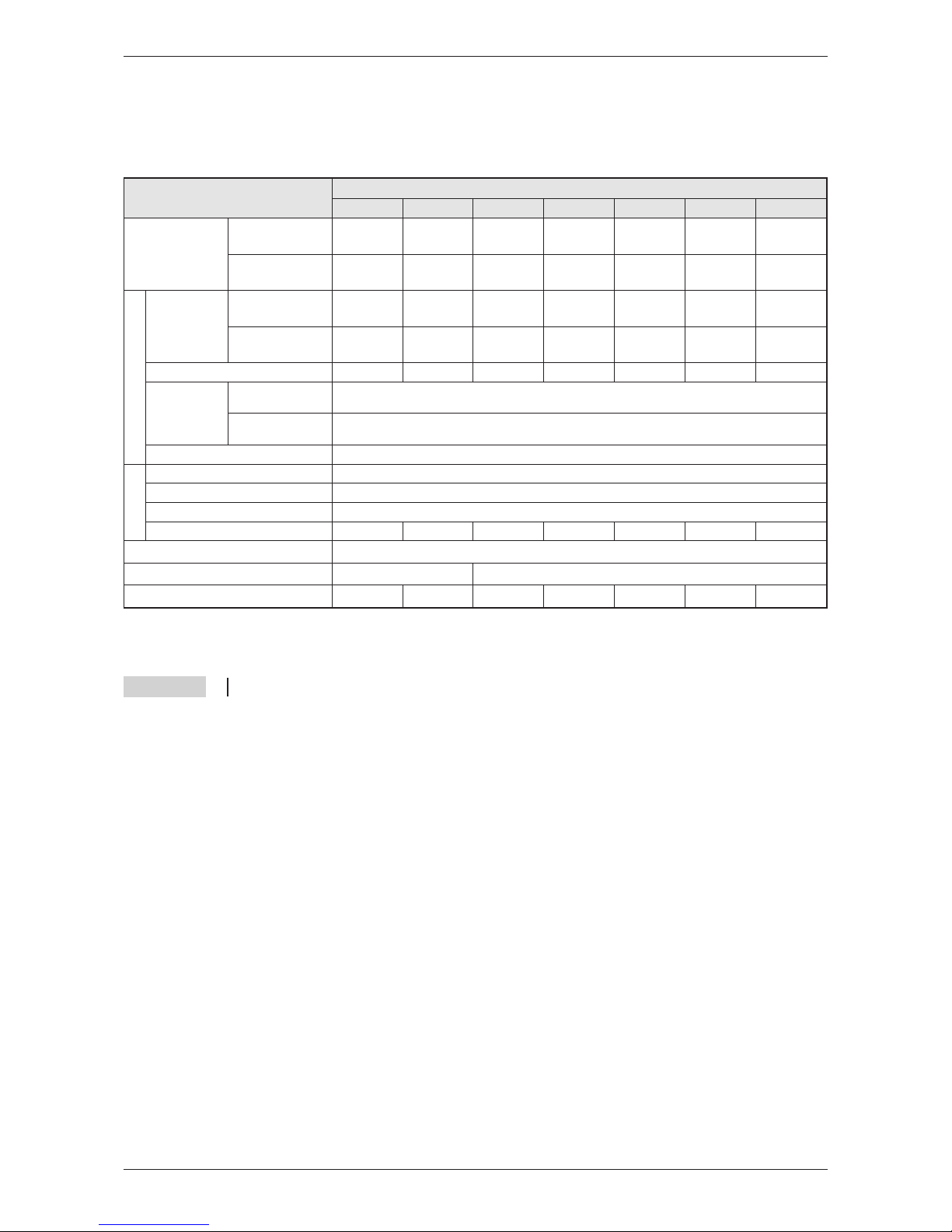
2.3 Model Specifications FR-E 500 EC
The following datas refer to the frequency inverters FR-E 520S EC und FR-E 540 EC.
Specifications
10 MITSUBISHI ELECTRIC
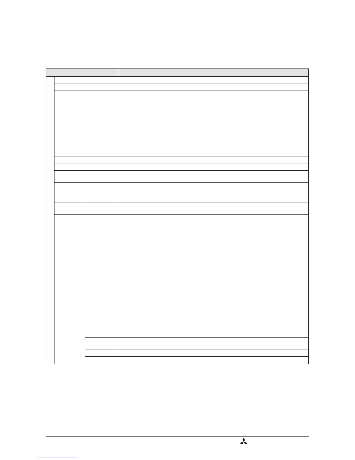
Type Description
Control signals
Control method Extended flux vector control with online auto tuning of motor data or V/f control
Modulation control Sine evaluated PWM, Soft PWM
Carrier frequency 0.7–14.5kHz (user adjustable)
Frequency range 0.2–400Hz
Frequency
resolution
Analog From terminals 2-5: 1/500 of maximum set frequency (input 5V DC); 1/1000
(input 10V, 20mA DC)
Digital 0.01Hz / 50Hz
Frequency precision ±0.5% of max. output frequency (temperature range 25°C ± 10°C) during analog input;
±0.01% of max. output frequency during digital input
Voltage/
Frequency characteristics
Base frequency adjustable from 0 to 400Hz;
constant torque or variable torque selectable
Possible starting torque ≥150% / 1Hz, ≥200% / 3Hz (for vector control or slip compensation)
Torque boost Manual torque boost; selectable between 0–30%
Acceleration/deceleration time 0.01; 0.1 to 3600s individual settings
Acceleration/deceleration
characteristics Linear or S-form course, user selectable
Braking/
torque
Regenerative 0.4k and 0.75k: 100% or more; 1.5k: 50% or more; 2.2k to 7.5k: 20% or more
DC-braking Braking time and braking moment adjustable,
Operating frequency: 0–120Hz, operating time: 0–10s, voltage: 0–30%
Current stall prevention
operation level Operation current level setting possible (0–200% variable), enable/disable selection
Voltage stall prevention
operation level Operation level is fixed, enable/disable selection
High-response current
restriction level Operation level is fixed, enable/disable selection
Motor protection Electronic motor protection relay (rated current user adjustable)
Frequency
setting values
Analog
input 0–5V DC, 0–10V DC, 0/4–20mA
Digital From control panel (parameter unit), RS485 or network
Input
signals
Starting signal Individual selection of forward / reverse run
Starting signal self retaining input
Multi-speed
selection
Up to 15 set speeds (each speed can be set between 0 and 400Hz;
speed can be changed via control panel or during operation)
2nd function Selects 2nd function (acceleration time, deceleration time, torque boost,
base frequency, electronic overcurrent protection)
Selection of
current input Frequency setting via current input signal 0/4 to 20mA DC
External
thermal input Stopping the inverter with an externally mounted thermal relay
PU<->external
operation Switch over between the operating modes “PU” and “External”
V/F<->flux
vector control External switching between V/F control and general-purpose flux vector control
Output stop Instant cutoff of inverter output (frequency and voltage)
Error reset The error indication (alarm signal) is reset with the reset of the protective function


(-C) User manual")