MOUNTING INSTRUCTIONS
Ensure that the flat roof waterproofing is compatible with the mounting system.The roof
drainage system has to be included in the planning of your solar plant.
In the case of very uneven roofs or roof waterproofing, compensatory measures may have to be taken in
order to ensure a uniform introduction of the load.
Necessary distances to roofedges have to be maintained.
The maximum field size depends on the type of roof.
For foil roofs, it is max. 10 m; for concrete roofs, it can also be larger in individual cases.
In the case of roofs with substrate or gravel roofing, it has to be ensured that a sufficiently non-slip
connection occurs.
Please check the existing pitch of the roofandwhether the mounting system has to be secured against
slipping.
Thesurface load is not permitted to exceedthe residual load-bearing capacity of the building!
The partial surface pressure, which acts on the roof membraneand insulation underthe base rails, is not
allowed under any circumstances to exceedthe maximum permissible surface pressure.
Current country-specific rules and regulations have to be observed.
Roof cleaning! In order to ensure that the base rails are supported across their entire surface, impurities
such as moss, leaves,dirt, stones, etc. have to be removed.
If there is a lightning protection system involved, it is important to determine theextent to which
integration by a certified lightning protection company is necessary. Whether or notthe lightning
protection requirements change as a result of the installation also has to be determined.
Due to static reasons, the installation of a single module row is not permitted!
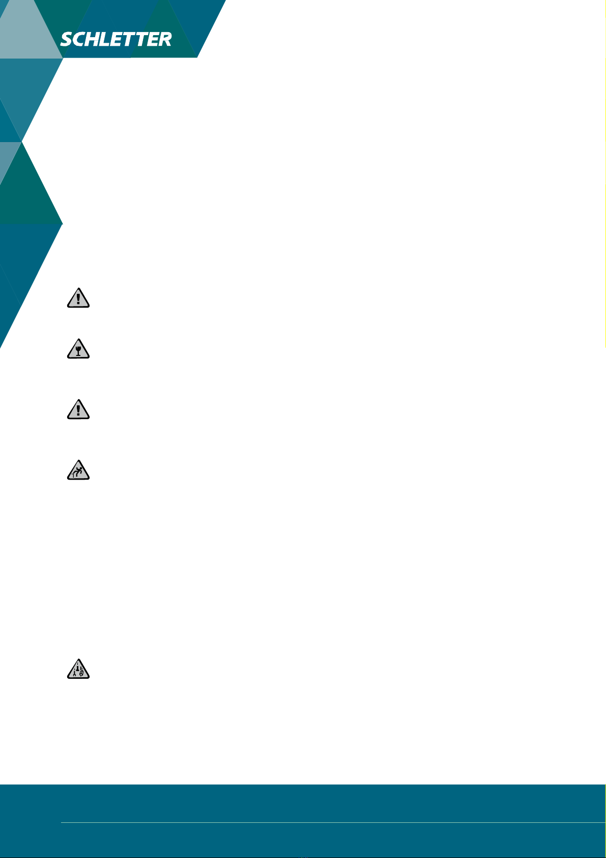
Prior to installation, the roofhas to be checked for damage of any kind, particularly water beading
or damage to the roof membrane. These should be documented with photos in order to be able to
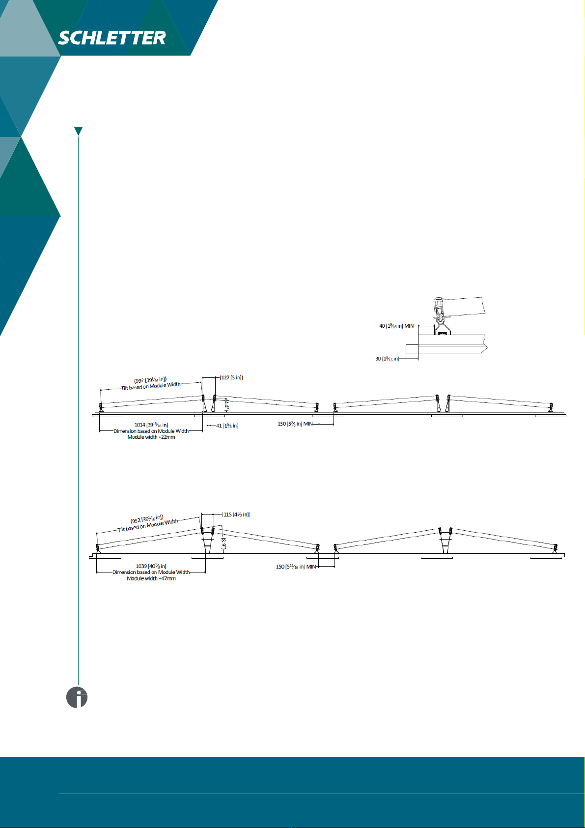
counteract any recourse claims. The system hasbeen developed for modules with a width of 950-1050
m m (standard module dimensions according to the current status). Other module dimensions on request
and separate verification. Information about module clamping pursuant to the manufacturer has to be
observed.
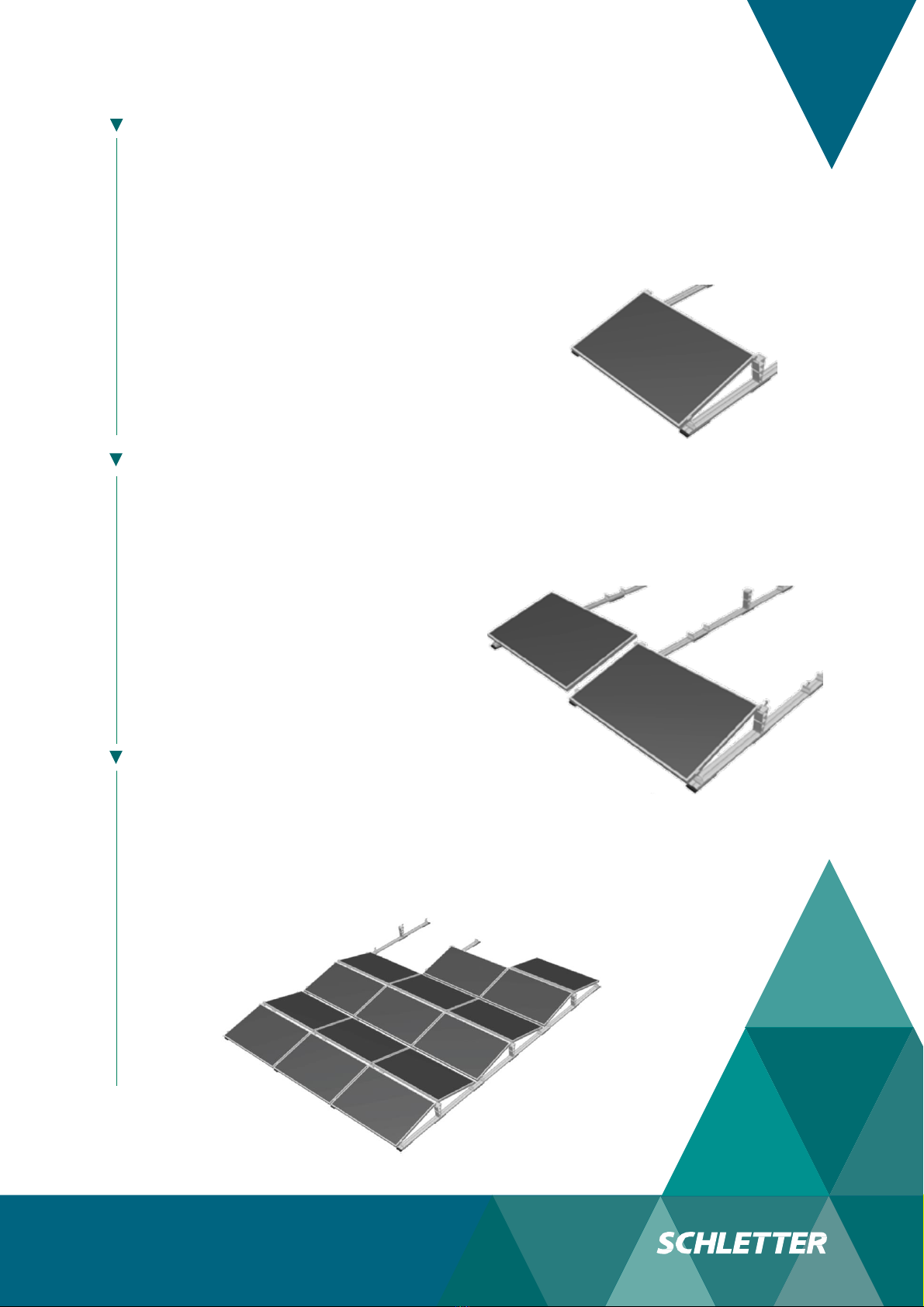
The FixGrid18 mounting system is fixed to the roofpurely with ballast (except special cases). A detailed
ballast calculation can be found in the project-related planning documents. The ballasting is calculated
in such a way that sliding, tilting and lifting of the rack is avoided.
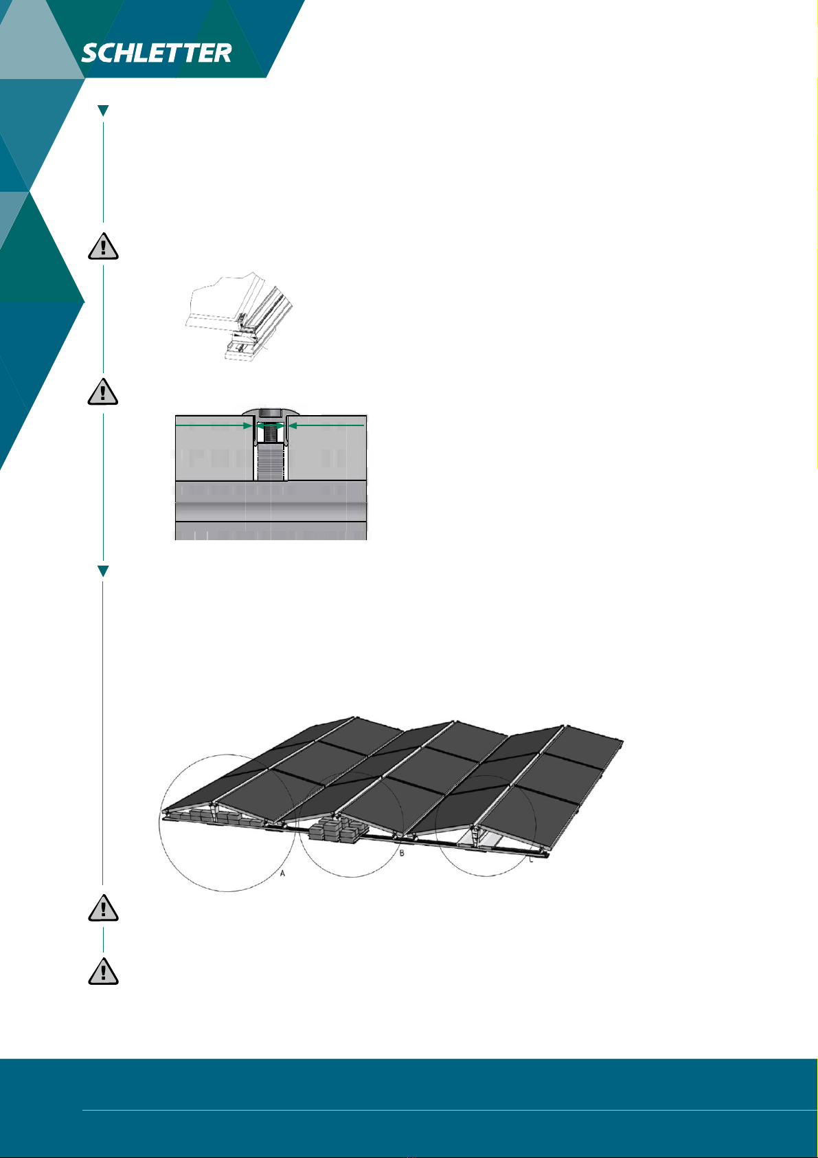
Use only original Schletter components!
No modifications to the modules are required to secure them. It is the client’s/installer’s
responsibility to ensure the clamp location is in accordance with the panel installation
manual.
All other markings, information on the number of modules and
additional information can be found in the project-specific
documents.
Usethecurrent mounting instructions! Accessible on our website:
www.schletter-group.com in the FixGrid18 section.
FIXGRID EAST-WEST I V1 I INSTALLATION MANUAL I
12-2020 SCHLETTER NA Inc. I SUBJECT TO CHANGE
WITHOUT NOTICE
3