HBK HBM Bruel & Kjaer MCS10 User manual

MCS10
ENGLISH DEUTSCH FRANÇAIS
Mounting Instructions
Montageanleitung
Notice de montage

Hottinger Brüel & Kjaer GmbH
Im Tiefen See 45
D-64293 Darmstadt
Tel. +49 6151 803-0
Fax +49 6151 803-9100
www.hbkworld.com
Mat.: 7-0111.0015
DVS: A04466 05 Y00 03
07.2022
EHottinger Brüel & Kjaer GmbH
Subject to modifications.
All product descriptions are for general information
only. They are not to be understood as a guarantee of
quality or durability.
Änderungen vorbehalten.
Alle Angaben beschreiben unsere Produkte in allge
meiner Form. Sie stellen keine Beschaffenheits- oder
Haltbarkeitsgarantie dar.
Sous réserve de modifications.
Les caractéristiques indiquées ne décrivent nos
produits que sous une forme générale. Elles
n'impliquent aucune garantie de qualité ou de
durabilité.
MCS10
ENGLISH DEUTSCH FRANÇAIS
Mounting Instructions

MCS10
TABLE OF CONTENTS
2
TABLE OF CONTENTS
1 Safety instructions 4................................................
2 Scope of supply 6...................................................
3 Markings used 7....................................................
3.1 The markings used in this document 7.................................
3.2 Symbols used on the sensor 7........................................
4 Application 9.......................................................
5 Structure and mode of operation 10....................................
6 Mechanical installation 11............................................
6.1 Important precautions during installation 11..............................
6.2 Conditions on site 11.................................................
6.3 Mounting the sensor 12...............................................
6.4 Quality of the customer's own attachment parts 14........................
6.5 Recommended fits for the customer's own attachment parts 15.............
6.6 Mounting position and force application 16..............................
7 Crosstalk 19........................................................
7.1 General information 19...............................................
8 Electrical connection 20..............................................
8.1 General information 20...............................................
8.2 EMC protection 20...................................................
8.2.1 Notes on installation 20...............................................
8.2.2 Notes on cabling 20..................................................
8.3 Pin assignment 21...................................................
9 TEDS transducer identification 23......................................
10 Maintenance 24.....................................................
11 Waste disposal & environmental protection 25...........................
12 Dimensions 26......................................................
12.1 MCS10-005-3C 26....................................................
12.2 MCS10-005-6C 27....................................................
12.3 MCS10-010-3C, MCS10-025-3C, MCS10-050-3C 28........................
12.4 MCS10-010-6C, MCS10-025-6C, MCS10-050-6C 29........................

3
MCS10
TABLE OF CONTENTS
12.5 MCS10-100-3C 30....................................................
12.6 MCS10-100-6C 31....................................................
12.7 MCS10-200-3C 32....................................................
12.8 MCS10-200-6C 33....................................................
12.9 Cable outlet for a three-component transducer 34.........................
12.10 Cable outlet for a six-component transducer 34...........................
12.11 Cable connection 35..................................................
13 Ordering number and accessories 36...................................
13.1 Ordering number MSC10 36...........................................
13.2 Connection cable K-KAB-M and 1-KAB146-6 38...........................
14 Specifications 40....................................................

MCS10
SAFETY INSTRUCTIONS
4
1 SAFETY INSTRUCTIONS
Appropriate use
The MCS10 multicomponent sensor is used to measure up to six loads, such as axial
force Fz, lateral forces Fx, Fy, bending moments Mx, My, and torsional moment Mz, in the
positive and negative signal direction. Although this only applies in the context of the
range stated in the specifications. Use for any purpose other than the above is deemed to
be non-designated use.
Multicomponent sensors may only be installed by qualified personnel in compliance with
the specifications and with the safety requirements and regulations of these mounting
instructions. It is also essential to observe the applicable legal and safety regulations for
the application concerned. The same also applies to the use of accessories.
The sensor is not intended for use as a safety component. For safe and trouble-free oper
ation, this sensor must not only be correctly transported, stored, sited and mounted but
must also be carefully operated and maintained.
Load-carrying capacity limits
The information in the technical data sheets must be complied with when using multi
component sensors. The respective specified maximum loads in particular must never be
exceeded. The following values set out in the specifications must not be exceeded:
SLimit forces and moments
SBreaking forces and moments
SPermissible dynamic loads
STemperature limits
SLimits of electrical load-carrying capacity
Use as a machine element
The multicomponent sensor can be used as a machine element. When used in this man
ner, it must be noted that, to favor greater sensitivity, transducers were not designed with
the safety factors usual in mechanical engineering. Please refer here to the technical
data and load-carrying capacity limits.
Accident prevention
In cases where a breakage or malfunction of the transducer would cause injury to per
sons or damage to equipment, the user must take appropriate additional safety mea
sures that meet at least the requirements of applicable safety and accident prevention
regulations issued by the German Social Accident Insurance Institutions (e.g. automatic
emergency shutdown, overload protection, catch straps or chains, or other fall protec
tion).

5
MCS10
SAFETY INSTRUCTIONS
Additional safety precautions
Multicomponent sensors cannot (as passive transducers) implement any safety-relevant
cutoffs. This requires additional components and constructive measures, for which the
installer and operator of the plant is responsible. The electronics conditioning the mea
surement signal should be designed so that measurement signal failure does not subse
quently cause damage.
The scope of supply and performance of the sensor covers only a small area of measure
ment technology. In addition, equipment planners, installers and operators should plan,
implement and respond to safety engineering considerations in such a way as to mini
mize residual dangers. Pertinent national and local regulations must be complied with.
General dangers of failing to follow the safety instructions
The multicomponent sensor corresponds to the state of the art and is failsafe. Residual
dangers may be involved if transducers are mounted, set up, installed and operated inap
propriately, or by untrained personnel. Everyone involved with siting, starting-up, maintain
ing or repairing a multicomponent sensor must have read and understood the mounting
instructions and in particular the technical safety instructions. Transducers can be dam
aged or destroyed by non-designated use, or by non-compliance with the mounting and
operating instructions, these safety instructions or any other applicable safety regula
tions (BG safety and accident prevention regulations) when using the transducers. Trans
ducers can break, particularly in the case of overloading. The breakage of a transducer
can also cause damage to property or injury to persons in the vicinity of the transducer.
Conversions and modifications
The design or safety engineering of the sensor must not be modified without our express
permission. Any modification shall exclude all liability on our part for any damage result
ing therefrom.
Qualified personnel
Qualified personnel are persons entrusted with the setup, mounting, startup and opera
tion of the product, who have the appropriate qualifications for their function.
This includes people who meet at least one of the three following requirements:
1. They know about the safety concepts of automation and as project personnel, are
familiar with these concepts
2. As automation plant operating personnel, they have been instructed how to handle the
machinery. They are familiar with the operation of the equipment and technologies
described in this documentation.
3. As commissioning engineers or service engineers, they have successfully completed
the training to
qualify them to repair the automation systems. They are also authorized to operate,
ground and label circuits and equipment in accordance with safety engineering stan
dards.

MCS10
SCOPE OF SUPPLY
6
2 SCOPE OF SUPPLY
SSensor in accordance with the ordering code
STest certificate of the individual components for the positive signal direction
SMounting instructions

7
MCS10
MARKINGS USED
3 MARKINGS USED
3.1 The markings used in this document
Important instructions for your safety are specifically identified. It is essential to follow
these instructions in order to prevent accidents and damage to property.
Symbol Significance
WARNING This marking warns of a potentially dangerous situ
ation in which failure to comply with safety require
ments can result in death or serious physical injury.
Notice This marking draws your attention to a situation in
which failure to comply with safety requirements can
lead to damage to property.
Important This marking draws your attention to important in
formation about the product or about handling the
product.
Tip This marking indicates application tips or other
information that is useful to you.
Information This marking draws your attention to information
about the product or about handling the product.
Emphasis
See …
Italics are used to emphasize and highlight text and
identify references to sections, diagrams, or external
documents and files.
3.2 Symbols used on the sensor
Read and note the data in this manual
CE mark
T The CE mark enables the manufacturer to guarantee that the
product complies with the requirements of the relevant EU direc
tives (the EU declaration of conformity can be found on the HBK
website at www.hbm.com).
MCS10
MARKINGS USED
8
Statutory waste disposal mark
The electrical and electronic devices that bear this symbol are
subject to the European waste electrical and electronic equip
ment directive 2002/96/EC.
The symbol indicates that, in accordance with national and local
environmental protection and material recovery and recycling
regulations, old devices that can no longer be used must be dis
posed of separately and not with normal household garbage
Marking in accordance with the requirements of SJ/T 11364-2014 and SJ/T
11363-2006 („China RoHS-2“)
Marking for products which contain hazardous substances
above the maximum concentration limit.
Part Name
Hazardous Substances
Lead
(Pb)
Mer
cury
(Hg)
Cad
mium
(Cd)
Hexavalent
Chromium
(Cr (VI))
Polybrominated
biphenyls
(PBB)
Polybrominated
diphenyl ethers
(PBDE)
Measure
ment Body O O O O O O
Metal
Housing O O O O O O
Small Parts
(e.g. screws,
pins,
sockets)
X O O O O O
This table is prepared in accordance with the provisions of SJ/T 11364.
SJ/T 11364
O: Indicates that said hazardous substance contained in all of the homogeneous mate
rials for this part is below the limit requirement of GB/T 26572.
!"#$"%&'()*+&$GB/T
26572,+-./0
X: Indicates that said hazardous substance contained in at least one of the homoge
neous materials used for this part is above the limit requirement of GB/T 26572.
!"#12$"34&'()*+56 GB/T
26572,+-.

9
MCS10
APPLICATION
4 APPLICATION
The multicomponent sensor measures forces and torques both statically and dynamically
in each loading direction. The sum of dynamic load and static initial load must however
not exceed the maximum capacity.
The sensor is maintenance-free and can be installed even in difficult to access points.
The electrical measurement signals can be transmitted to remote measuring points and
control rooms.
The housing protects the application from moisture and various media. No load or force
may be applied to the sensor via the housing.
The MCS10 multicomponent sensor is reliably protected against electromagnetic inter
ference. It has been tested in accordance with harmonized European standards. The
product carries the CE mark.

MCS10
STRUCTURE AND MODE OF OPERATION
10
5 STRUCTURE AND MODE OF OPERATION
The MCS10 multicomponent sensor is designed with a monolithic measuring body on
which strain gages (SG) are installed. The measuring body is enclosed in a housing. On
the housing is a terminal box with connector plugs for the measuring bridge power supply
and transferring output signals.

11
MCS10
MECHANICAL INSTALLATION
6 MECHANICAL INSTALLATION
6.1 Important precautions during installation
Notice
Transducers are precision measuring instruments and must be handled carefully. Knocking
or dropping them can lead to unexpected overloading with permanent
damage, even when in measuring mode. Make sure that the transducer cannot be over
loaded, including while it is being mounted. The specifications list the permissible limits
for mechanical stresses.
SHandle the transducer with care.
SEnsure that the transducer cannot be overloaded.
WARNING
There is a danger of the transducer breaking if it is overloaded. This can cause danger for
the operating
personnel of the system in which the transducer is installed.
Implement appropriate safety measures to avoid overloading and to protect against
resulting dangers.
SIf alternating loads are expected, use a (medium strength) threadlocker to glue the
screws into the counter thread to exclude prestressing loss due to screw slackening.
SComplying with the mounting dimensions is essential for correct operation.
Important
Even if the unit is installed correctly, the zero point adjustment made at the factory can
shift by up to approx. 0.5% of the sensitivity. If this value is exceeded, we advise you to
check the mounting conditions. If the residual zero drift when the unit is removed is greater
than 1% of the sensitivity, please send the transducer back to the Darmstadt factory for
testing.
6.2 Conditions on site
Protect the transducer from weather conditions such as rain, snow, ice, and salt water.
Ambient temperature
There is wide ranging compensation for the effects of temperature on the zero signal and
on sensitivity (see the “Specifications” chapter, starting on page 40). To obtain optimum

MCS10
MECHANICAL INSTALLATION
12
measurement results, the nominal (rated) temperature range must be observed. Constant
or very slowly changing temperatures are best.
Temperature gradients in the transducer, which can result from cooling or heating on one
side, have an effect on the zero point of the transducer. A radiation shield and all-round
thermal insulation produce noticeable improvements, but they must not be allowed to set
up a force shunt.
Moisture and corrosion protection
The multicomponent sensor is encapsulated and therefore very insensitive to moisture.
The sensor attains protection class IP67 as per DIN EN 60259. Nevertheless, sensors
must be protected against the long-term effects of exposure to moisture.
The sensor must be protected against aggressive chemicals that could attack it.
Deposits
Dust, dirt and other foreign matter must not be allowed to accumulate sufficiently to
divert some of the measuring force onto the housing, thus distorting the measured value
(force shunt).
6.3 Mounting the sensor
Use the internal centering to center the sensor to the customer's own attachment parts
(see Fig. 6.1).
1. Use the positioning pins provided to align the sensor to the top and bottom of the con
necting flange. It is advisable not to exceed a phase angle error tolerance of ±0.1° for
the elongated holes on the customer's own attachment parts (aligning the axis of the
pins to the axis of the force).
2. Use hexagon socket screws per DIN EN ISO 4762 of property class 8.8, 10.9 or 12.9
(see Tab. 6.1) to connect the flange. The screw length is dependent of the customer's
own attachment parts.
We recommend DIN EN ISO4762 cylinder head screws, blackened, smoothheaded,
lightly oiled (μtot = 0.125), permitted size and shape variance as per DIN ISO 4759,
Part 1, product class A.
3. Fasten all screws with the specified torque (see Tab. 6.1). Fit the screws by tightening
them diagonally in two steps (50% and 100% of the full tightening torque).
13
MCS10
MECHANICAL INSTALLATION
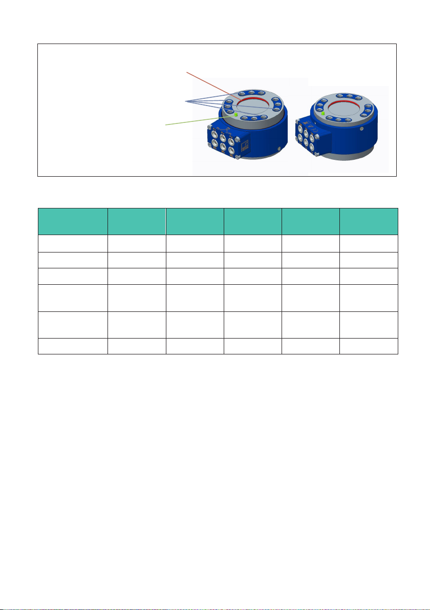
"red marking" →Internal centering surface
We recommend using this centering surface
to center the customer's own load applica
tion/mounting parts.
"blue marking" →Load application surface
This is the only surface for force application
and output.
"green marking" →Positioning pin
Please use the centering pin for positioning
and aligning the load application/mounting
parts to the sensor.
Transducer top
(measuring side)
Transducer bottom
(fixed side)
Fig. 6.1 Mechanical interface description
Measurement
range
MCS10-005 MCS10-010 MCS10-025
& -050
MCS10-100 MCS10-200
Centering Ø30 H8 Ø45 H8 Ø45 H8 Ø60 H8 Ø60 H8
Alignment pin Ø2.5 m6 Ø4 m6 Ø4 m6 Ø4 m6 Ø4 m6
Screw thread M5 M8 M8 M10 M12
Tightening
torque
6 Nm 25 Nm 36 Nm 72 Nm 145 Nm
Property
classes
8.8 8.8 10.9 10.9 12.9
Number 12 12 12 12 12
Tab. 6.1 Fastening screw characteristics

MCS10
MECHANICAL INSTALLATION
14
Load application plate
Centering washer
Positioning pin
(fixed to the sensor)
Min. gap 1 mm
Multicomponent sensor
Mounting base
Min. gap 1 mm
Fig. 6.2 Typical assembly
Important
Dry screw connections can result in different and higher coefficients of friction (see
VDI 2230, for example). This means a change to the required tightening torques. The
required tightening torques can also change if you use screws with a surface or property
class other than that specified in Table 1, as this affects the coefficient of friction.
6.4 Quality of the customer's own attachment parts
The customers' own attachment parts (contact surfaces) must meet the following condi
tions to achieve optimum and repeatable measurement results:
15
MCS10
MECHANICAL INSTALLATION
SThey must be sufficiently stiff so that they do not deform under load. The general rule
here is that the thickness of the connection elements should be approximately one
third of the transducer height.
The contact surface has ideal flatness and stiffness if a tolerance of 0.005 mm is not
exceeded both without load and under load.
SThey must be paint-free.
SThey must be made of steel and have a minimum hardness of 40HRC. For types
MCS10-005 and MCS10-010, a titanium customer-side construction is also possible.
The hardness of the stainless steel transducer body is at least 42HRC for steel and
about 30HRC for titanium.
SThey should have a surface roughness of ≤ Ra1.6. Ideally, the surface should be
ground. Ensure plane parallelism.
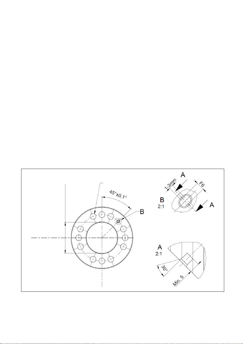
6.5 Recommended fits for the customer's own attachment parts
The fitting dimension of the transducer's internal centering is ØH8, so we recommend
combining the fits H8 and g6 for the load application elements (see Fig. 6.3 and Fig. 6.4).
To stop the transducer getting stuck during installation, an elongated hole should be cho
sen as the counterpart for the alignment pin. This elongated hole should be radially
aligned to the center of the pitch circle and the fit for the width should ideally be F6
(see Fig. 6.3).
lateral force
direction
lateral force
direction
screw through holes
ØH7 or ØH8
internal center
elongated hole for pin
orientation
Fig. 6.3 Load application plate and mounting base

MCS10
MECHANICAL INSTALLATION
16
Fig. 6.4 Centering washer
6.6 Mounting position and force application
The mounting position of the multicomponent sensor is determined by the arrows on the
terminal box. If the forces and moments are applied in the direction of the arrow, the con
nected HBM amplifiers will return a positive output signal (see section 12 “Dimensions”,
page 26).
In the three-dimensional coordinate system, the so-called right-hand rule clearly defines
the orientation of the three force directions and the moments rotating clockwise around
the axes of the positive force directions (also see Fig. 6.5).
Fig. 6.5 Right-hand rule
17
MCS10
MECHANICAL INSTALLATION
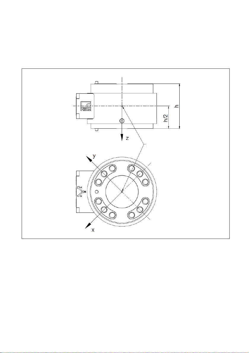
The point of origin of the multicomponent sensor coordinates is the geometric center of
the sensor (see Fig. 6.6). When preparing the test certificate, the forces (without
moments) and the moments (without forces) are applied on the measuring side and
measured at the point of origin. This is achieved using an appropriately designed load
application adapter. This way, a lateral force does not generate a bending moment, for
example.
Point of origin
Fig. 6.6 Sensor point of origin
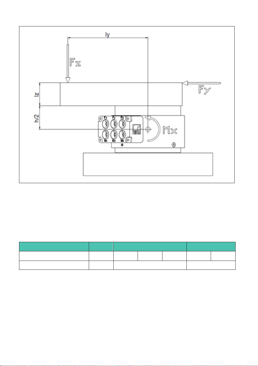
The forces and moments should be applied as near to the sensor as possible. If the force
is applied far away from the sensor, the bending moment increases and can affect the
measurement results of the other components. If the forces are applied in the application
in such a way that they do not go through the point of origin, the moments that are then
generated (force times lever arm) must be observed (see Fig. 6.7).
MCS10
MECHANICAL INSTALLATION
18
Fig. 6.7 Example diagram of forces and the resulting moments
When calculating the bending moment generated by lateral forces, half the height of the
sensor (see also Tab. 6.2) must be taken into account to determine the lever arm, as the
point of origin is at the center of the sensor. The maximum permitted loads stated in the
specifications must be complied with, even if measurement is not taking place in
individual axes.
BG1 BG2 BG3
050 010 025 050 100 200
Sensor height [mm] 45 62 77
Tab. 6.2 Sensor heights
Table of contents
Languages:


