LINKUP LP400 User manual

Operator’s Manual | LP400 1
LP400
OPERATOR’S MANUAL
Conveyor Assembly, Operation & Maintenance

2Operator’s Manual | LP400

Operator’s Manual | LP400 3
CONTENTS
CONTENTS...............................................................................................3
INTRODUCTION .......................................................................................4
1. INSTRUCTIONS FOR SAFETY ............................................................5
2. PROTECTING THE ENVIRONMENT....................................................6
3. STANDARD OF MANUFACTURE.........................................................6
4. TOOLS / PPE REQUIRED FOR SITE ASSEMBLY...............................6
4.1 TOOLS REQUIRED FOR SITE ASSEMBLY.............................6
4.2 RECOMMENDED MINIMUM PPE.............................................6
5. LIFTING & POSITIONING .....................................................................7
5.1 LIFTING CONVEYOR SECTIONS ............................................7
5.2 MECHANICAL LIFTING ............................................................7
5.3 SUPPORTING CONVEYOR ON SITE ......................................8
6. DELIVERY & SITE SET-UP...................................................................8
6.1 DELIVERY.................................................................................8
6.2 SITE SET-UP.............................................................................9
6.3 HOPPER ASSEMBLY .............................................................14
6.4 HOPPER MOUNTING .............................................................15
6.5 CONTROL BOX.......................................................................16
6.6 CONTROL BOX WIRING DIAGRAM.......................................17

4Operator’s Manual | LP400
INTRODUCTION
The LINKUP®Conveyor range is designed to provide years of reliable service
throughout its working life.
The unique design of the LINKUP®Conveyor range is the result of over 50 years
of research and hands-on experience in the conveyor industry. Experience,
attention to detail, a commitment to quality and excellent service results in
customer satisfaction every time.
IMPORTANT
Read, understand, and obey these safety rules and operating
instructions before operating this machine.
Only competent authorized personnel shall be permitted to operate
this machine. This manual should be considered a permanent part of
your machine and should always remain with the machine. If you
have any questions, please contact the manufacturer:
InterQuip USA LLC
4 Duke Place
Norwalk, CT 06854
(203) 322-2600
info@interquip.net

Operator’s Manual | LP400 5
1. INSTRUCTIONS FOR SAFETY
When using LINKUP® Conveyors, all
safety recommendations, assembly
instructions, and operating instructions
found in this Operator’s Manual MUST be
followed when using the equipment. All
persons who use equipment must be
acquainted with this manual and must be
aware of any potential hazards. Equipment
should not be used by children at any time
and should always be watched and
managed by competent personnel. When
equipment is being used within close
proximity to personnel, suitable taped
off areas should be in place to establish
a safety zone area.
It's imperative that you observe the
accident prevention regulations in force in
your state, province or locale, including the
general rules of occupational health and
safety.
The manufacturer shall not be liable for any
changes made to the equipment or any
damage resulting from such changes.
Use Common Sense and Planning When Installing and Operating the Machine.
Keep Hands and Limbs Away from Moving Belt.
Always Wear Correct PPE.
•Failure to follow instructions listed below may result in electric shock,
fire and/or serious injury. Always isolate from electrical supply before
carrying out maintenance, including changing the belt.
•Always have a designated covered in walkway when using equipment
over pedestrians.
•It is not recommended to erect the equipment in high wind or icy
weather conditions.
•Check that all components for your conveyor insulation is current prior
to starting the installation.
•EQUIPMENT IS HEAVY. Minimum of 2 persons required to handle
each section. Use lifting equipment if necessary, and follow proper
manual lifting procedures to prevent back injury.
BE AWARE OF THE FOLLOWING: DO NOT CLIMB ON CONVEYORS!
•ELECTROCUTION HAZARDS
•EXPLOSION AND FIRE HAZARDS
•SETUP HAZARDS
•FALL HAZARDS
•COMPONENT DAMAGE HAZARD

6Operator’s Manual | LP400
2. PROTECTING THE ENVIRONMENT
Built into the design and the manufacturing of the Conveyor, recycling
unwanted materials has been carried out instead of disposing of them
as waste. Packaging should be sorted, taken to the local recycling
center, and disposed of in an environmentally safe way. This Conveyor
has been designed to assist in recycling materials on site where at all
possible.
3. STANDARD OF MANUFACTURE
The LINKUP®Conveyor range has been Planned, Designed, and Built with Safety in mind.
Pinch points and trap points have been Guarded by Design, where at all possible without
restricting the maximum operational capacity of the conveyor function. With the relevant
health and safety regulations built into the design, the LINKUP® Range of conveyors are
known for their safety and well-being for the Operator.
•Each section can be manhandled with two people for assembly on site.
•Manufactured to a high standard of fabrication
•Welded and constructed by trained and coded welders
•Built with UL®approved components.
•Designed and Built in the USA
4. TOOLS / PPE REQUIRED FOR SITE ASSEMBLY
4.1 TOOLS REQUIRED FOR SITE ASSEMBLY
•Adjustable Wrench
•Socket Wrench Set
4.2 RECOMMENDED MINIMUM PPE
•Hard Hat
•Gloves
•Goggles
•Safety Footwear
Operator’s Manual | LP400 7
5. LIFTING & POSITIONING
5.1 LIFTING CONVEYOR SECTIONS
•At least 2 people should handle individual sections
•Sections and components over 50 lbs. will require mechanical handling.
WARNING!
OBSERVE CORRECT LIFTING PROCEDURES AT ALL TIMES.
LINKUP®400 Sections
Length
Width
Height
Weight
Head Unit with Drum Motor
76 ¼“
28”
12 ½”
228 lbs
Tail / Base Tension Unit
76 ¼“
28”
12 ½”
160 lbs
Intermediate Section
74 ¼“
21 ¾”
12 ½”
103 lbs
Hopper
39”
39”
14”
95 lbs
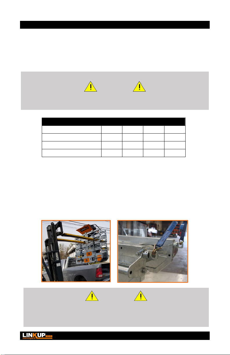
5.2 MECHANICAL LIFTING
•Conveyors and conveyor sections that need to mechanically lifted
on-site will need to be done by a confident/trained personal. All
lifting chains and straps should be safely attached through
conveyor frame or scaffold tube holes that are within the main
conveyor frame.
WARNING!
ENSURE THAT YOUR CONVEYOR IS CORRECTLY AND SAFELY
LIFTED AT ALL TIMES. ENSURE THAT NOBODY IS UNDERNEATH
THE CONVEYOR WHEN IT IS BEING LIFTED.
8Operator’s Manual | LP400
5.3 SUPPORTING CONVEYOR ON SITE
•Standard single support legs are provided to assist in supporting the
Conveyor on-site with on-site supports required by others as needed.
Scaffolding holes are provided within the conveyor frame to assist when
building into scaffolding. Further securing points are placed on lifting
handles each end of the Conveyor.
•Recommended supporting points on each length of Conveyor are as
follows:
12' Long = 2# Supports one at each end.
18' Long = 2# Supports one at each end.
24' Long = 3# Supports one at each end and one in the center.
30' Long = 3# Supports one at each end and one in the center.
HELPFUL TIPS & RECOMMENDATIONS
THE CONVEYOR SHOULD BE SUPPORTED AT REGULAR INTERVALS.
KEEP A CLEAR SPACE UNDER THE CONVEYOR TO PREVENT MATERIAL BUILD UP.
CHECK SUPPORTS OF CONVEYORS REGULARLY FOR SAFE SUITABILITY.
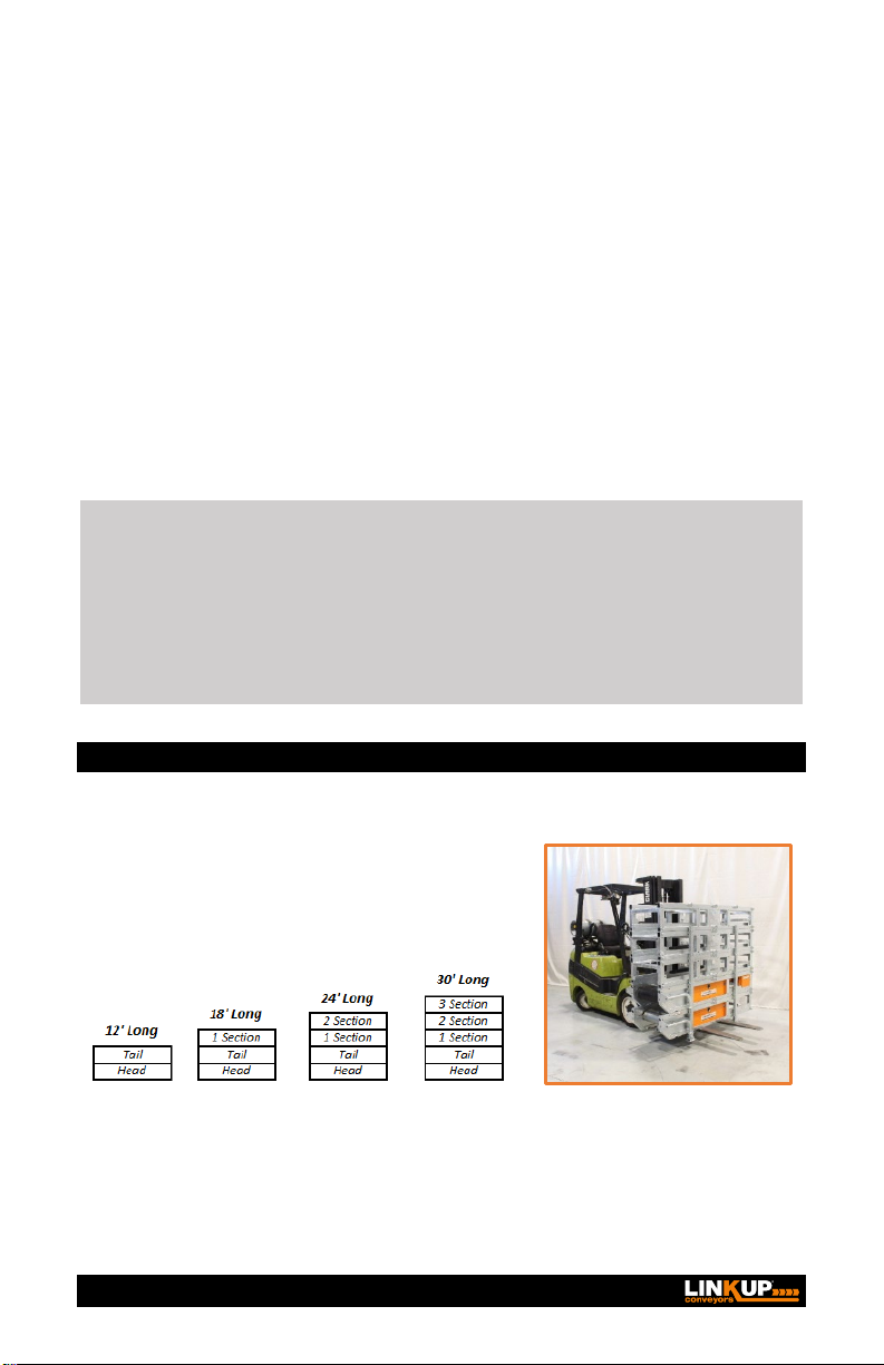
6. DELIVERY & SITE SET-UP
6.1 DELIVERY
LINKUP® 400 Conveyors are shipped to site
in 6' long stacks one conveyor per stack
complete with belt ready for your installation
as follows:
Each conveyor can be lifted with a fork truck on-site. They can then be positioned as close
to the final location as possible. Check that you have received the correct length and
number of conveyors and hoppers, etc. Acquaint the assembly team with this Operator's
Manual.

Operator’s Manual | LP400 9
6.2 SITE SET-UP
1. Unwrap and dismantle the conveyors from the shipping stack.
2. Select the tail unit, (Non-Drive roller) and position in the
approximate area for Feeding/Loading.
3. Select the intermediate section(s) and attach and bolt to the tail
unit and secure bolts tightly.
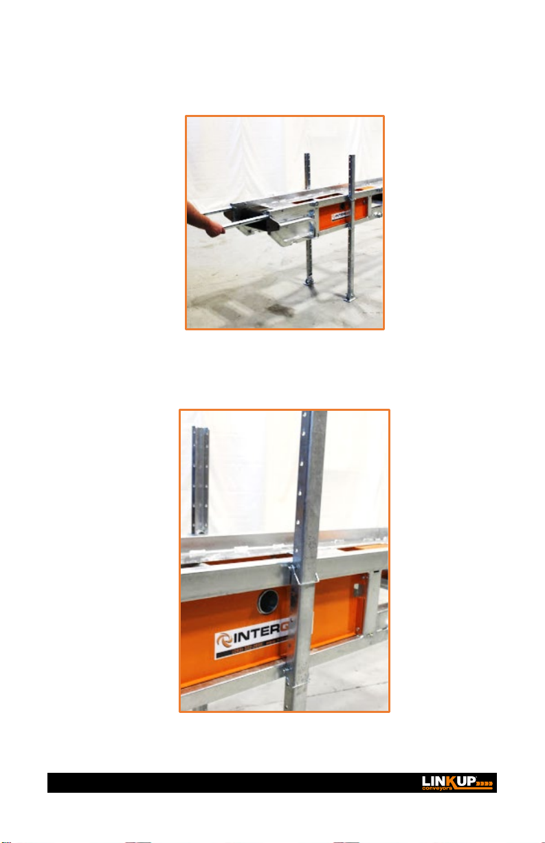
10 Operator’s Manual | LP400
4. Position the first set of support legs, ensuring the conveyor is
clear from the ground to give a material free area under the
conveyor to provide a space to keep clean from material buildup.
5. Continue with the further sections as needed, supporting as need
along its length.
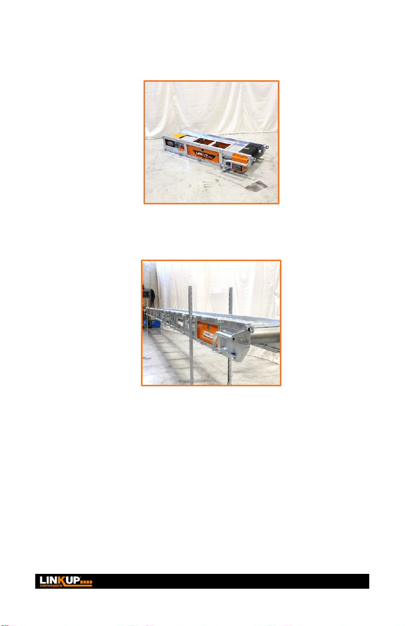
Operator’s Manual | LP400 11
6. Select the Head Drive unit, which is the most substantial section,
and lifting assistance may be needed depending on the site
conditions. Position and secured to the main sections.
7. Ensure the conveyor is safely positioned and supported.
Supports can be from below or from above, depending on the site
conditions and what is available on the site.
8. FIT THE STANDARD ENDLESS (VULCANIZED JOINT) BELT:
•Ensure that the drum on the Base Tension Unit is as far
forward (towards the motor end) as possible.
•Roll out the belt to its full length alongside the assembled
conveyor.
•Lift one end of the belt up and loop over the tail drum of the
base tension unit. This should be carried out with a minimum
of two people.

12 Operator’s Manual | LP400
•Mechanically lift one side of the conveyor or lift conveyor to
give room to enable the belt to be fed under the conveyor
frame and over the temporary support trestles. As the belt is
being inserted into the frame, ensure the cleats are pointing
down, and the belt is returning on the return blocks ether side
along the conveyor length.
•Loop the other end of the belt over the head unit drum. Useful
Hint: In some instances where access is tight or difficult, it
may be advantageous to use a leaver bar.
•Ensure that the belt is centrally positioned on the head and
tail drums and along the length of the conveyor, both top and
underside.
. . . . . . . . . . . . . . . . . . . . . . . . . . . . . . . . . . . . . . . . . . . . . . . . . . . .
An endless belt is provided as standard. If a clipped belt is
requested or supplied, follow these instructions:
•FITTING A CLIPPED BELT is done by feeding the belt in
from the top/drive drum of conveyor if possible, on the
underside of the frame with the cleats pointing in the down
position.
•Ensure the returning belt rides over the side slide bars and
bring belt around the tail drum and up the conveyor to a
position that the belt pin can be inserted.
•Wrap the remaining belt around the drive drum and down the
top of the conveyor to meet the two ends together.
•Join the two ends and insert the hinge pin and secure the pin
with crimping the two retaining washers on each end of the
hinge pin if the ends of the belt don’t meet adjust the tail drum
to release the belt as needed.
. . . . . . . . . . . . . . . . . . . . . . . . . . . . . . . . . . . . . . . . . . . . . . . . . . . .
Washer
Clamped
End of hinge
pin within the
width of belt
Operator’s Manual | LP400 13
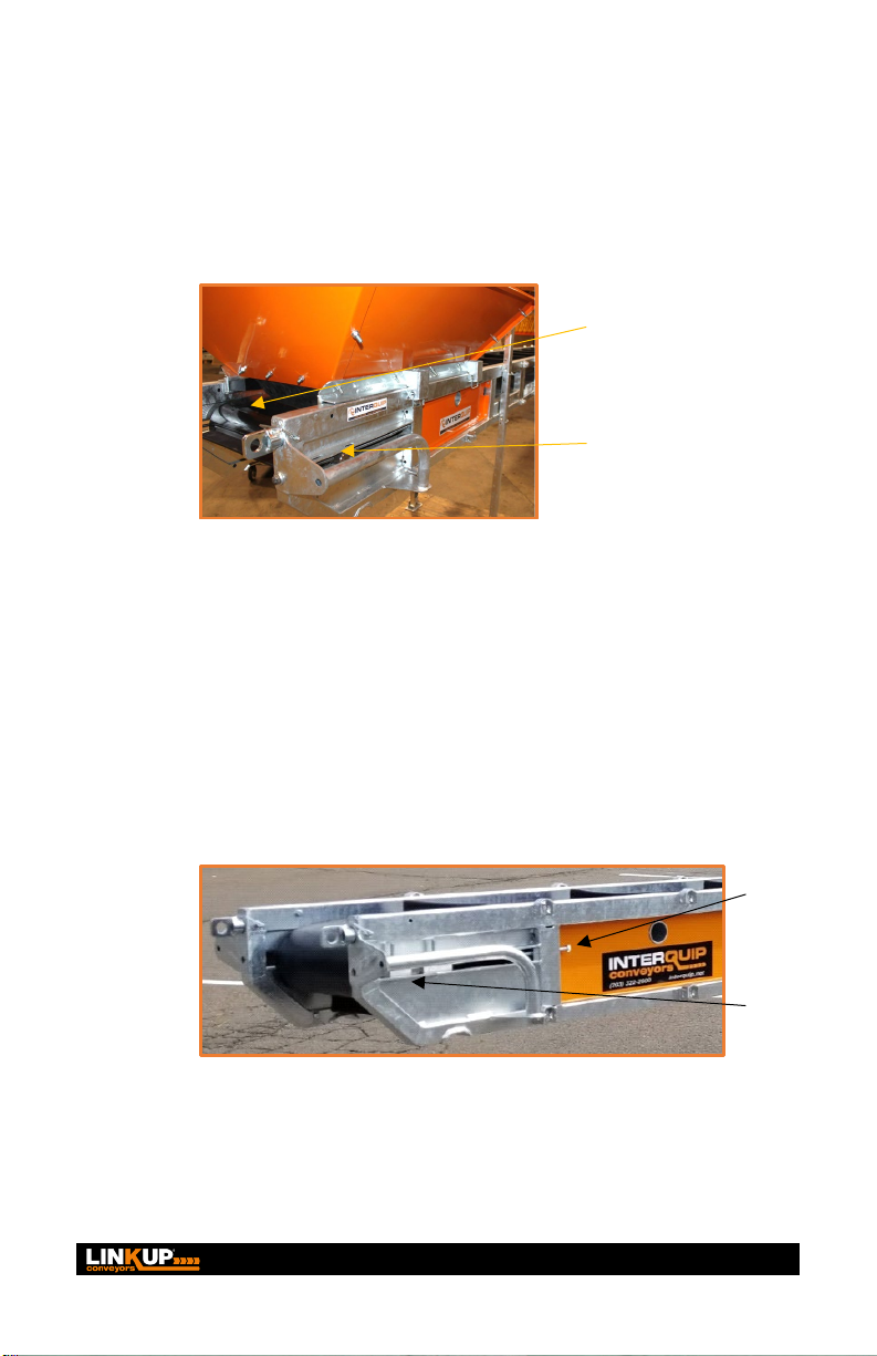
9. Tensioning of the Belt takes place at the tail drum. Adjust drum
tensioning stud bars each side evenly (A). Turning clockwise will
pull the tail drum back to tension the belt. Anticlockwise will
loosen the belt when required. Adjust (A) Evenly each side to
matching measurement each side from drum shaft to the
mainframe.
10. Tracking of the Tail Drum should be carried out as described
above, ensuring that when the belt is running in its main direction
of use, the belt must be adjusted to run within the center of the
conveyor frame and tail drum.
11. Tracking of the Head Drum should be adjusted from one side
(A) to ensure the belt is run within the center of the conveyor
frame and tail drum. Release 2 bolts (B) adjust and re-secure
when adjustment is complete.
(A)
Adjusting
Stud Bar
Tail Drum
(A)
(B)
14 Operator’s Manual | LP400
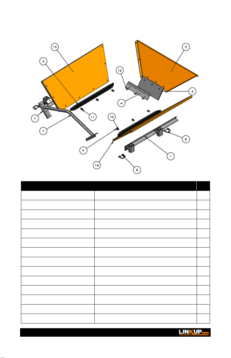
6.3 HOPPER ASSEMBLY
No. Part No. Description Qty
1 LP407-01 Hopper Bracket Assembly Left Side 1
2 LP407-02 Hopper Bracket Assembly Right Side 1
3 LP407-04 Hopper Rear Panel 1
4 LP407-07 Flap Bracket 1
5 LP400-SP-02 Machined Nylon Return Wear Strip 2
6 LP407-00-05 Reinforced Rubber Flap 1
7 LP407-03 Hopper Brace Bar Assembly 1
8 FX-PIN-8MM-BZP Zinc-Plated Steel Pin with Wire Lock 4
9 FX-BOLT-M8-25-PS-BZP-8.8 Bolt M8 25mm Plain Steel Bright Zinc Plated 8.8 6
10 FX-WASHER-M8-CF-BZP C Form Washer M10 Plain Steel Bright Zinc Plated 12
11 FX-LNUT-M8-BZP Locking Nut M10 Steel Bright Zinc Plated 8.8 6
12 FX-CBOLT-M8-20-PS-BZP-4.8 Coach Bolt M10 30mm Plain Steel Bright Zinc Plated 8.8 3
13 LP407-05 Hopper Side Panel 1 1
14 LP407-06 Hopper Side Panel 2 1
Operator’s Manual | LP400 15
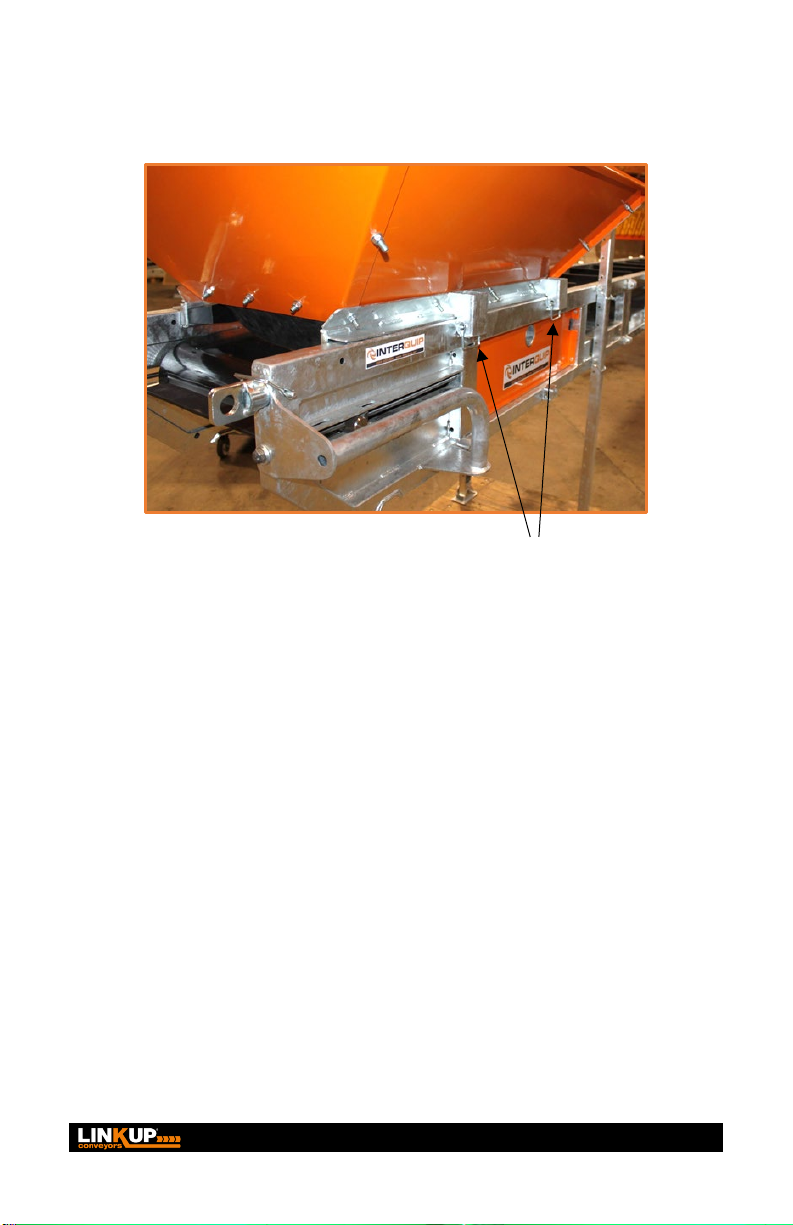
6.4 HOPPER MOUNTING
Standard Hopper can be placed along the conveyor length in either
direction locating the brackets and securing 4 pins, two on each side
(A) to connect.
When using the hopper along its length, the area of the belt entering
the hopper must be zoned off for safety and performance of conveyor.
(A)
16 Operator’s Manual | LP400
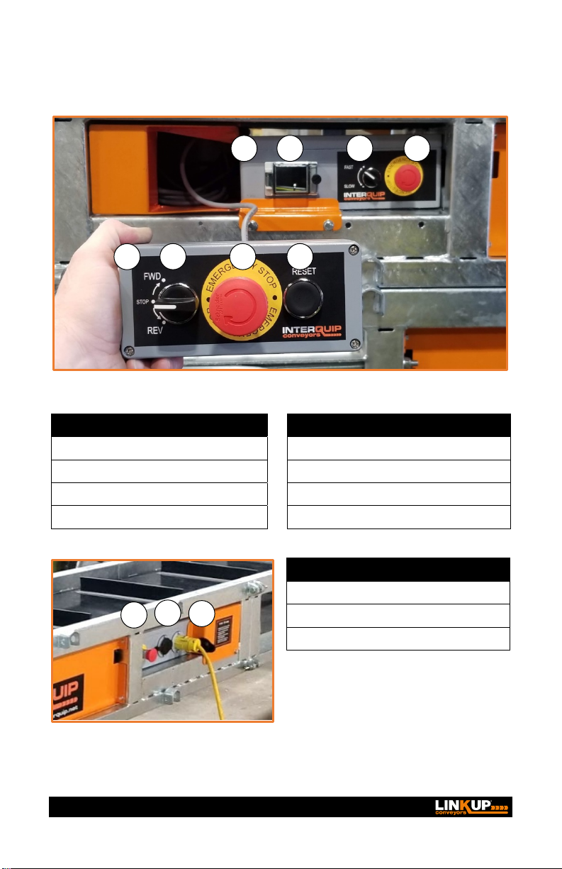
6.5 CONTROL BOX
No. Description
No. Description
1 Removable Control Box
5Pendant Control Box on 15FT Lead
2 Digital Display Sight Glass
6 Forward/Reverse Directional Control
3 Two Speed Controls
7 Emergency Stop
4 Emergency Stop
8 Reset Control
No. Description
9 Emergency Stop
10 110V Power OUT (to next unit)
11 100V 20AMP Power IN
1
2
3
4
5
6
7
8
9
10
11

Operator’s Manual | LP400 17
6.6 CONTROL BOX WIRING DIAGRAM
WARNING!
ALL ELECTRICAL WORK MUST BE CARRIED OUT BY A QUALIFIED ELECTRICIAN
AND SHALL COMPLY WITH RELEVANT STANDARDS AND LEGISLATION.

18 Operator’s Manual | LP400

Operator’s Manual | LP400 19

20 Operator’s Manual | LP400
LP400
OPERATOR’S MANUAL
Rev.1 : 2020-12-07
InterQuip USA LLC
4 Duke Place
Norwalk, CT 06854
(203) 322-2600
info@interquip.net
Table of contents
Popular Accessories manuals by other brands


Bamo
Bamo MAXIMAT VK C instruction manual

Klarstein
Klarstein 10032797 manual

Greystone Energy Systems
Greystone Energy Systems NTRC Networking Series installation instructions

Quasar
Quasar QFI-SWITCH Installation

Sensopart
Sensopart FT 50 RLA 70-L8 Mounting and operating instructions

ActiVHeat
ActiVHeat 9BHWSL3 Series user manual