idronaut Ocean Seven 303Plus User manual

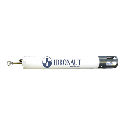
OCEAN SEVEN 303Plus CTD
MULTIPARAMETER PROBE

OCEAN SEVEN 303Plus CTD
MULTIPARAMETER PROBE
OPERATOR’S MANUAL
November 2019
Copyright @ 1982-2016 Idronaut S.r.l. All rights reserved.
OCEAN SEVEN and Idronaut are registered trademarks of Idronaut S.r.l.
Other products and services mentioned in this document are identified by the trademarks or service marks of their respective companies or
organizations. No part of this publication, or any software included with it, may be reproduced, stored in a retrieval system, or transmitted in
any form or by any means, including photocopying, electronic, mechanical, recording or otherwise, without the prior written permission of
the copyright holder. Idronaut S.r.l. provides this document as is without warranty of any kind either expressed or implied including, but not
limited to, the implied warranties of merchantability and fitness for a particular purpose. Idronaut S.r.l. may make changes of improvements
in the equipment, software, firmware, or specifications described in this document at any time and without notice. These changes may be
incorporated in new releases of this document. This document may contain technical inaccuracies or typographical errors. Idronaut S.r.l.
waives responsibility of any labour, materials, or costs incurred by any person or party as a result of using this document. Idronaut S.r.l. shall
not be liable for any damages (including, but not limited to, consequential, indirect or incidental, special damages, or loss of profits or data)
even if they were foreseeable and Idronaut S.r.l. has been informed of their potential occurrence arising out of or in connection with this
document or its use.

IDRONAUT –Brugherio (MB) OCEAN SEVEN 303Plus PROBE 02-2019
OCEAN SEVEN 303Plus PROBE
IMPORTANT REMARKS
CONDUCTIVITY MEASUREMENT
1) To obtain the best accuracy, the conductivity sensor and therefore the probe
sensor head, must be immersed in clean seawater for at least 15 minutes before
measurements. For fresh water application, the sensor does not require any
hydration.
2) When the conductivity sensor is not in use, it is kept dry. Therefore, when the
conductivity sensor is placed in water, very small bubbles may remain attached
to the platinum ring electrodes (seven). If such a thing happens, the measured
value of conductivity will be lower than the true one. To remove these air
bubbles, degrease the inside of the conductivity cell using cotton buds wetted
with the Conductivity Sensor Cleaning Solution or with liquid soap. Gently rotate
the cotton bud against the whole internal surface of the quartz cell. This will wet
the platinum electrodes thus reducing the surface tension of the cell and
considerably decreasing the risk of trapped air bubbles.
OXYGEN MEASUREMENT
Most polarographic oxygen sensors take 5 to 10 minutes after they have been
switched on to polarize and become stable. To overcome this limitation, the
IDRONAUT OS303 probe has been fitted with a small internal rechargeable battery,
to maintain polarization of the oxygen sensor continuously. However, if the probe is
not used for several months, the polarization battery may become completely
discharged resulting in damage to the battery. It is recommended that the probe
should be switched ON (and streaming real-time data) for at least a few hours every
2 to 3 months, to maintain this polarization battery in a healthy condition.
pH MEASUREMENT
The ph and reference sensors should never be allowed to completely dry out. For
short-term storage of up to one day, the probe’s sensor head can simply be
immersed in clean water. If the probe remains unused for periods longer than one
day, always place the hydrating caps on both sensors. The pH sensor cap should be
filled with the pH7 Buffer Solution (or simply with clean water). The reference sensor
cap should be filled with the Idronaut Reference Sensor Storage Solution (or even
with KCl saturated solution).
PROBE WASHING
After use, the probe must be always washed with fresh water in order to remove any
salt water residual or dirtiness.

IDRONAUT –Brugherio (MB) OCEAN SEVEN 303Plus PROBE 02-2019
LIFETIME AND HOW TO REPLACE THE IDRONAUT SENSORS
The Idronaut sensors are all pressure compensated and, in particular, the physical
sensors (pressure, temperature and conductivity) can last many years, if properly
used. They are high-quality sensors, as they are well known by oceanographers to
measure salinity with great accuracy.
The nitrate and ammonia sensors do not need to be removed and replaced when
they become exhausted with the passing of time or physically broken by pressure, if
the membrane cap has not been properly filled with (its specific) electrolyte. In fact, it
is enough to replace their specific membrane cap.
If thoroughly maintained by their respective hydrating caps and solutions, the
Idronaut pH and reference sensors can last several years. The sensor replacement
requires that the closure nuts on the top head of the probe be unscrewed with a
common screwdriver and the cylindrical housing be removed (this takes very few
minutes).The wire sensors are tin soldered on their respective connection points
placed on the printed circuit board.
All sensor heads have a standard 12 mm diameter and are provided with two o-rings
(Parker 2-12) for sealing.
This means that every sensor can be fitted in any of the five sensor head holes.The
pressure sensor is a high-quality transducer, which can last many years if properly
used. Its replacement is not very easy and, moreover, it requires a Dead Weight
Tester System to obtain the factory calibration accuracy of 0.05% full scale.

IDRONAUT –Brugherio (MB) OCEAN SEVEN 303Plus PROBE 02-2019
TABLE OF CONTENTS
1INTRODUCTION .................................................................................................................................. 1
1.1 PROBE DESCRIPTION........................................................................................................................ 1
1.2 Portable READER................................................................................................................................. 1
1.3 FSK TELEMETRY - PORTABLE DECK UNIT ..................................................................................... 2
1.4 PROBE MANAGEMENT PROGRAMMES........................................................................................... 2
1.5 SENSOR SPECIFICATIONS................................................................................................................ 2
1.6 OPTIONAL SENSORS......................................................................................................................... 4
1.7 ELECTRONIC SPECIFICATIONS........................................................................................................ 4
1.8 PHYSICAL CHARACTERISTICS......................................................................................................... 4
1.9 CALCULATIONS .................................................................................................................................. 4
1.9.1 Salinity .................................................................................................................................................. 4
1.9.2 Density.................................................................................................................................................. 5
1.9.3 Oxygen.................................................................................................................................................. 5
1.9.4 pH calculation and pH correction in relation to the sample temperature.............................................. 7
1.9.5 Conductivity compensated at 20oC...................................................................................................... 8
1.9.6 Seawater sound speed......................................................................................................................... 8
1.9.7 Pressure to depth conversion............................................................................................................. 10
1.10 THE SENSORS .................................................................................................................................. 10
1.10.1 Pressure transducer............................................................................................................................ 10
1.10.2 Temperature sensor............................................................................................................................ 10
1.10.3 The Idronaut seven-ring conductivity sensor...................................................................................... 11
1.10.4 The Oxygen Sensor............................................................................................................................ 12
1.10.5 pH and Reference sensors................................................................................................................ 14
1.10.6 The redox sensor................................................................................................................................ 15
2INSTALLATION AND START-UP....................................................................................................... 19
2.1 SHIPPING LIST................................................................................................................................. 19
2.2 INSTALLATION PROCEDURE .......................................................................................................... 19
2.3 HOW TO OPERATE THE PROBE..................................................................................................... 19
2.4 START-UP PROCEDURE.................................................................................................................. 19
2.4.1 Probe Start-up -Verbose operating mode......................................................................................... 19
2.4.2 Probe Start-up Non-Verbose operating mode.................................................................................... 20
2.4.3 Telemetry Portable Deck Unit Start-up............................................................................................... 20
2.5 The Probe Main Menu ........................................................................................................................ 21
2.5.1 Operator Interface............................................................................................................................... 21
3COMMANDS....................................................................................................................................... 23
3.1 DATA ACQUISITION.......................................................................................................................... 23
3.1.1 Real Time............................................................................................................................................ 23
3.2 CALIBRATION.................................................................................................................................... 23
3.2.1 Temperature sensor calibration.......................................................................................................... 24
3.2.2 Pressure sensor calibration ................................................................................................................ 24
3.2.3 Conductivity sensor calibration........................................................................................................... 25
3.2.4 Oxygen Sensor Calibration................................................................................................................. 26
3.2.5 pH Sensor Calibration........................................................................................................................ 27
3.3 MEMORY MANAGEMENT................................................................................................................. 28
3.4 SERVICE Menu .................................................................................................................................. 28
3.4.1 Set-up ................................................................................................................................................. 28
3.4.2 Advanced Set-up ................................................................................................................................ 30
3.4.3 Real-Time Clock Set-up...................................................................................................................... 31
3.4.4 Raw Counts ........................................................................................................................................ 31
3.4.5 Raw mV .............................................................................................................................................. 31
3.4.6 Rights.................................................................................................................................................. 32
3.4.7 Firmware upgrading............................................................................................................................ 32
3.5 SHUTDOWN....................................................................................................................................... 32
3.6 CHANGE OPERATING MODE .......................................................................................................... 32
4Probe MAINTENANCE...................................................................................................................... 33
4.1 OXYGEN SENSOR ............................................................................................................................ 33
4.1.1 Green membrane................................................................................................................................ 33

IDRONAUT –Brugherio (MB) OCEAN SEVEN 303Plus PROBE 02-2019
4.1.2 Refilling oxygen sensor cap with electrolyte....................................................................................... 34
4.1.3 Membrane replacement (oxygen membrane cap).............................................................................. 34
4.1.4 Replacement of membrane can be done using the OXYGEN SENSOR MAINTENANCE KIT:........ 34
4.1.5 Oxygen sensor cleaning ..................................................................................................................... 36
4.1.6 Oxygen sensor check in the absence of oxygen................................................................................ 36
4.2 REFERENCE SENSOR...................................................................................................................... 36
4.3 pH SENSOR ...................................................................................................................................... 37
4.4 CONDUCTIVITY SENSOR................................................................................................................. 38
4.4.1Conductivity sensor cleaning.............................................................................................................. 38
4.4.2 Wetting the Conductivity sensor before laboratory calibration tests................................................... 38
4.5 REDOX SENSOR............................................................................................................................... 38
4.6 TEMPERATURE SENSOR ................................................................................................................ 39
4.7 PRESSURE SENSOR........................................................................................................................ 39
4.8 OXYGEN SENSOR POLARIZATION BATTERY............................................................................... 39
4.8.1 RTC battery......................................................................................................................................... 39
4.9 ROUTINE MAINTENANCE SCHEDULE............................................................................................ 39
4.9.1 Monthly maintenance.......................................................................................................................... 39
4.9.2 Quarterly maintenance........................................................................................................................ 39
5ITERM –WINDOWS TERMINAL EMULATION PROGRAMME........................................................ 40
5.1 DISTRIBUTED FILES......................................................................................................................... 40
5.2 INSTALLATION .................................................................................................................................. 40
5.3 PROGRAMME MENUS AND FUNCTIONS....................................................................................... 40
5.4 TOOLBAR........................................................................................................................................... 43
5.5 START-UP SWITCHES...................................................................................................................... 43
5.6 TROUBLESHOOTING........................................................................................................................ 44
6PTP COMMUNICATION PROTOCOL ............................................................................................... 44
6.1 TIME-OUTS on command .................................................................................................................. 44
6.2 ERROR/DIAGNOSTIC MESSAGES.................................................................................................. 44
6.3 PACKET DESCRIPTION.................................................................................................................... 45
7FSK - PORTABLE DECK UNIT.......................................................................................................... 46
7.1 Probe checkout with the portable deck unit........................................................................................ 47
7.2 Final checkout with the shipboard sea cable...................................................................................... 47
7.3 FSK - TELEMETRY FINE TUNING.................................................................................................... 48
APPENDIX A –HIGHLY PRECISE PRESSURE TRANSDUCER.................................................................. 50
APPENDIX B - STANDARD SEA WATER TABLE……………………………………………………………..... 52

SECTION ONE - INTRODUCTION
IDRONAUT –Brugherio (MB) OCEAN SEVEN 303Plus PROBE 02-2019
1
1 INTRODUCTION
This section describes the main components of the OCEAN SEVEN 303Plus CTD multiparameter
probe.
1.1 PROBE DESCRIPTION
The OCEAN SEVEN 303Plus multiparameter CTD probe, is the result
of Idronaut’s 20 years experience in the design and manufacture of
high quality fast response marine instrumentation. It offers a
combination of 16-bit high resolution data accuracy, with long-term
sensor stability, making this probe an ideal choice for on-line profiling.
The OCEAN SEVEN 303Plus probe does not require a pump or any
other external device to flush the sensors.
The OCEAN SEVEN 303Plus PROBE in the standard configuration is
equipped with seven sensors to measure: Pressure, Temperature,
Conductivity, Dissolved Oxygen, pH, Reference, Oxidation-reduction
potential (REDOX). Salinity is automatically calculated from
conductivity, temperature and pressure sensor signals.
The slim line of the probe and the pressure-compensation of sensors
permit operation in fast water profiling or in fixed depth monitoring
down to 1500 metres depth. The response time constant is 50 msec.
for all parameters except for oxygen, pH and Redox, which have a 3
sec. time constant. The electronic boards are fitted in an AISI 316
stainless steel sealed housing; one oceanographic connector, located
on the top cover, provides the probe power supply and data exchange
with a suitable external device. On the opposite end, the sensor area
is protected against accidental bumps with an AISI 316 stainless steel
protective cage.
The OCEAN SEVEN 303Plus PROBE is microprocessor-controlled and can measure and transmit
sensor data through a shielded coaxial cable via telemetry. Thanks to the high speed data conversion
and acquisition, micro-profiles can be easily obtained. The user can interface the probe with an
asynchronous terminal, or a Personal Computer equipped with a terminal emulation programme.
When using the telemetry, an additional deck unit is required to convert serial, RS232C type signals
(coming from a PC communication port) into telemetry signals (and vice versa) which flow
superimposed on the probe power supply along the probe cable. OEM Version of the probe are
available upon request with RS232C or 5V TTL interfaces.
The probe is operated through commands, which are selected from a list, or a menu, of possible
choices. Parallel to the menu interface, a computer-oriented interface has been implemented,
allowing the execution of the same commands to be performed in a quick and efficient (from
a Computer’s point of view) way.
Those customers who plan to make use of the computer-oriented interface will find it helpful to look at
the REDAS programme which can be supplied with the OCEAN SEVEN 303Plus PROBE. The
programme allows the user to collect and save data in real-time.
1.2 PORTABLE READER
The OCEAN SEVEN 303Plus CTD equipped with
the FSK-Telemetry portable deck unit can be
interfaced with a portable lightweight and
extremely rugged reader based on a high-
performance Intel® XScale™ processor and on
the Windows Mobile™ software for Pocket PC.
Through this device, it is possible to perform the
operations usually performed by means of a
portable personal computer, but without all
limitations that the use of a portable computer in
the field and in hostile environments normally
implies, like: battery endurance, display reading

SECTION ONE - INTRODUCTION
IDRONAUT –Brugherio (MB) OCEAN SEVEN 303Plus PROBE 02-2019
2
under sunlight, water and dust tightness, weight, etc. The “Portable Reader” interfaces the OCEAN
SEVEN 303Plus probe through a built-in RS232-C interface and a dedicated terminal emulation
programme, specifically developed for the Windows Pocket PC operating system. This programme
interfaces the OCEAN SEVEN 303Plus probe and allows the operator to dialogue with the probes
directly thus performing: sensor calibration, data acquisition, probe configuration, etc. All these
operations are possible thanks to the OCEAN SEVEN 303Plus probe smartness included in the
management firmware. Furthermore, the “Portable Reader” not only shows in real time data sent by
the OS 303Plus probe, but also stores it. Data is stored in text files using the “Portable Reader” main
or extension “Flash” memory, which can be later transferred to a desktop personal computer using the
Microsoft ActiveSync programme. Data storage capability of the “Portable Reader” is limited only by
the size of the installed “Flash” Compact memory card. The “Portable Reader” can operate for up to 15
hours continuously. Autonomy of the interfaced OCEAN SEVEN 303Plus probe depends on the
battery of the PORTABLE DECK UNIT.
1.3 FSK TELEMETRY - PORTABLE DECK UNIT
The PORTABLE DECK UNIT powers and interfaces, by
coaxial oceanographic cables, the CTD with a personal
computer RS232C. The deck unit is provided with a
transceiver (modem) which allows half-duplex
communication with the probe. The unit is provided with an
internal mains rechargeable lead battery (12V DC, 7 A/h)
which permits probe operation even in the absence of the
mains supply and guarantees up to 50 hours of continuous
probe and deck unit operation. Telemetry power supply: 30
V DC (max 0.3A@12 V). Dimensions: 340 x 300 x 160 mm.
Weight: 6.5 kg.
1.4 PROBE MANAGEMENT PROGRAMMES
IDRONAUT programmes designed for the Windows 98se/ME/2000/XP operating systems allow the
operator to communicate with the OCEAN SEVEN 303Plus CTD multiparameter probe to perform
attended or unattended data acquisitions. The programme packages comprise:
ITERM: IDRONAUT Terminal Emulation Programme and Probe Management Programme to easily
communicate with the OCEAN SEVEN 303Plus CTD multiparameter probe. Diagnostic and
dedicated functions are included.
REDAS:Real-time data acquisition, processing and presentation programme which allows the
numerical display and plotting of the standard sensors and the derived variables such as
salinity, sound speed, density, according to UNESCO formulas and recommendations.
1.5 SENSOR SPECIFICATIONS
The OCEAN SEVEN 303Plus CTD multiparameter probe can be equipped with the following
IDRONAUT sensors to measure:
Parameter Range Accuracy Resolution Time Constant
Pressure 0..1000 dbar(3) 0.05 % F.S. 0.0015 % F.S. 50 ms
Temperature -1.. +50 °C 0.005 °C 0.001 °C 50 ms
Conductivity
Salt water 0.. 70 mS/cm 0.007 mS/cm 0.001 mS/cm 50 ms (1)
Fresh water 0..7000 µS/cm 5 µS/cm 0.1 µS/cm 50 ms (1)
Oxygen 0.. 50 ppm 0.1 ppm 0.01 ppm 3 s (2)
0.. 500 %sat. 1 % sat. 0.1 % sat. 3 s (2)
pH 0..14 pH 0.01 pH 0.001 pH 3 s
Redox +/-1000 mV 1 mV 0.1 mV 3 s

SECTION ONE - INTRODUCTION
IDRONAUT –Brugherio (MB) OCEAN SEVEN 303Plus PROBE 02-2019
3
(1) At 1 m/second flow rate.
(2) In air.
(3) Other standard pressure transducers available have 10, 40, 100, 200, 500, 2000, 3000 dbar
ranges.
The following parameters are calculated from CTD sensors signals:
▪SALINITY, SOUND SPEED, SIGMA-T (according to UNESCO 1978 formula);
▪FRESH WATER CONDUCTIVITY corrected at 20°C and at 25°C;
▪OXYGEN % SATURATION to OXYGEN ppm CONVERSION (according to UNESCO 1986 formula -
Millero).

SECTION ONE - INTRODUCTION
IDRONAUT –Brugherio (MB) OCEAN SEVEN 303Plus PROBE 02-2019
4
1.6 OPTIONAL SENSORS
The OCEAN SEVEN 303Plus CTD can be optionally equipped with the Highly Precise (0.01%)
Pressure Sensor and the ION selective electrodes: ammonia, nitrate and chloride.
Parameter Range Accuracy Resolution Time Constant
Pressure 0..4000 dbar 0.01% F.S. 0.002 % F.S. 50 ms
Ammonia 0..100 mg/l-N 0.1 mV
Nitrate 0..100 mg/l-N 0.1 mV
Chloride 0.5..18000 mg/l-N 0.1 mV
1.7 ELECTRONIC SPECIFICATIONS
Real-time data output rate: 8 Hz (conversion into engineering units takes place using the probe
internal resources), 12 Hz using REDAS software.
Communication: Telemetry, RS232C, Asynchronous TTL (0..5VDC).
Baud Rate: 9600 bps.
Protocol: [Verbose] friendly operator interface with built-in help.
[Non Verbose] binary and/or ASCII data transmission.
A/D converter: 16-bit, resolution, range 0..2.5 VDC, 12 multiplexed analogue inputs.
Supply Voltage: 9..30 VDC, nominal 12 VDC.
Supply Current: 50 mA @ 12 V DC.
Cable: The OCEAN SEVEN 303Plus CTD multiparameter probe operates
with the standard Rochester coaxial armoured cables (1/10, 1/8, 1/4,
inch) and with sea cables having a total resistance up to 250 ohms.
1.8 PHYSICAL CHARACTERISTICS
Housing: 150 bar (AISI 316L) 300 bar (Titanium grade 2)
Dimensions:
housing diameter 43 mm 48 mm
total length 700 mm 705 mm
Weight: in air 1.6 kg 3.7 kg
in water 0.8 kg 2.8 kg
1.9 CALCULATIONS
Unless otherwise specified, the computation of algorithms is taken from UNESCO technical papers in
the marine science document no. 44 "Algorithms for computations of fundamental properties of
seawater" 1983.The shown algorithms are written in ANSI "C" language.
1.9.1 Salinity
The formula used for this calculation is as defined by UNESCO 1978 and successive modifications.
RT35(xt) = (((1.0031e-9*xt-6.9698e-7)*xt+1.104259e-4)*xt+2.00564e-2)*xt+0.6766097
SAL(xr,xt) = ((((2.7081*xr-7.0261)*xr+14.0941)*xr+25.3851)*xr-0.1692)*xr+0.0080
+(xt/ (1.0+0.0162*xt))*(((((-0.0144*xr+0.0636)*xr-0.0375)*xr-0.0066)
* xr - 0.0056) * xr + 0.0005)
C(xp) = ((3.989e-15 * xp - 6.370e-10) * xp + 2.07e-5) * xp
B(xt) = (4.464e-4 * xt + 3.426e-2) * xt + 1.0
A(xt) = -3.107e-3 * xt + 0.4215
CND = Conductivity / 42.91400391
RT = CND / (RT35(T) * (1.0 + C(P) / (B(T) + A(T) * CND)))

SECTION ONE - INTRODUCTION
IDRONAUT –Brugherio (MB) OCEAN SEVEN 303Plus PROBE 02-2019
5
RT = sqrt(ABS(RT));
DT = Temperature - 15.0
SAL78 = sal(RT,DT)
Where:
P = Pressure in decibar
T = Temperature in °C (IPTS-68)
CND = Conductivity ratio, (Conductivity expressed in mS/cm)
SAL78 = Salinity (PSS-78)
1.9.2 Density
r1(xt) = (((((6.536332e-9*xt-1.120083e-6)*xt+1.001685e-4)*xt-9.095290e-3)*xt+6.793952e-2)*
xt - 28.263737)
r2(xt) = ((((5.3875e-9 * xt - 8.2467e-7) * xt + 7.6438e-5) * xt -4.0899e-3) * xt + 8.24493e-1)
r3(xt) = ((-1.6546e-6 * xt + 1.0227e-4) * xt - 5.72466e-3)
k35(xp )= ((5.03217e-5 * xp + 3.359406) * xp + 21582.27)
e(xt) = ((9.1697e-10 * xt + 2.0816e-8) * xt -9.9348e-7)
bw(xt) = ((5.2787e-8 * xt - 6.12293e-6) * xt + 3.47718e-5)
c(xt) = ((-1.6078e-6 * xt - 1.0981e-5) * xt + 2.2838e-3)
aw(xt) = (((-5.77905e-7 * xt + 1.16092e-4) * xt + 1.43713e-3) * xt - 0.1194975)
b1(xt) = ((-5.3009e-4 * xt + 1.6483e-2) * xt + 7.944e-2)
a1(xt) = (((-6.1670e-5 * xt + 1.09987e-2) * xt - 0.603459) * xt + 54.6746)
kw(xt) = ((((-5.155288e-5 * xt + 1.360477e-2) * xt - 2.327105) * xt + 148.4206) * xt - 1930.06)
r3500 = 1028.1063;
r4 = 4.8314e-4;
dr350 = 28.106331;
d = 1.91075e-4;
pres = pres / 10.0; /* Scale to BAR */
sr = sqrt(fabs(sal));
sig = (r4 * sal + r3(temp) * sr + r2(temp)) * sal + r1(temp);
v350p = 1.0 / r3500;
sva = (-sig * v350p) / (r3500 + sig);
sigma = sig + dr350;
svan = sva * 1.0e8;
if (pres = 0) { sigmaT = sigma;}
b = bw(temp) + e(temp) * sal;
a = (d * sr + c(temp)) * sal + aw(temp);
k0 = (b1(temp) * sr + a1(temp)) * sal + kw(temp);
dk = (b * pres + a) * pres + k0;
gam = pres / k35(pres);
pk = 1.0 - gam;
sva = sva * pk + (v350p + sva) * pres * dk / (k35(pres) * (k35(pres) + dk));
svan = sva * 1.0e8;
v350p = v350p * pk;
dr35p = gam / v350p;
dvan = sva / (v350p * (v350p + sva));
SigmaT = (dr350 + dr35p - dvan);
Where:
press is expressed in dbar; temp is expressed in C; Sal is expressed in ppt.
1.9.3 Oxygen
Calculation of the oxygen content in parts per million (ppm) is carried out in three steps.

SECTION ONE - INTRODUCTION
IDRONAUT –Brugherio (MB) OCEAN SEVEN 303Plus PROBE 02-2019
6
1.9.3.1Calculation of solubility
The following constants are required for calculation of solubility:
a1 = -173.4292 a3 = 143.3483 b1 = -0.033096 b3 = -0.001700
a2 = 249.6339 a4 = -21.8492 b2 = 0.014259 cnv = 1.428
The following variable is required for the calculation of solubility:
tempK = tempC + 273.15
the formula is:
r1 = a1 + (a2 x (100/temp)) + (a3 x ln (temp/100)) + (a4 x temp/100)
r2 = salinity x (b1 + (b2 x (temp/100)) + (b3 x (temp/100 x temp/100)))
Solubility (mg/l) = cnv x exp (r1 + r2)
1.9.3.2Calculation of % saturation
The following proprietary coefficients are required for the calculation of % saturation to compensate
the IDRONAUT membrane permeability to oxygen due to the temperature and pressure variation
respectively. Saturation % = Coeff. x O2(1) x SlopeO2x exp(T1x C1+ Pressure x C2)
Where:
C1= - 0.029
C2= 0.000115
Coeff. = Stirring effect and barometric pressure compensation (*)
SlopeO2= 1/ exp(T2* C1) x 02(2) / 100
O2(1) = Oxygen sensor reading in counts
O2(2) = Oxygen sensor reading in counts during calibration
T1= Temperature sensor reading in °C
T2= Temperature sensor reading in °C during calibration
Pressure = Pressure reading in dbar
1.9.3.3Calculation of ppm
The formula is:
ppm (mg/l) = Saturation x Solubility / 100
1.9.3.4Oxygen ppm calculated as defined by UNESCO 86 recommendations
UNESCO 86 (Millero) formula, constants and variables are the following:
ln C0 = a0+ a1/ T + a2/ T2+ a3/ T3+ a4/ T4- S x (b0 + b1/ T + b2/ T2)
O2mgkg-1 = (O2sat x exp(ln C0)) / 100
where:
T = absolute temperature in °C
sal = salinity in PSU (IPSS-78)
O2sat = Oxygen sensor output expressed in percentage of saturation
a0= -138.74202
a1= 1.572288 E5
a2= -6.637149 E7
a3= 1.243678 E10

SECTION ONE - INTRODUCTION
IDRONAUT –Brugherio (MB) OCEAN SEVEN 303Plus PROBE 02-2019
7
a4= -8.621061 E10
b0= 0.020573
b1= -12.142
b2= 2363.1
The above was taken from NOVA THALASSIA Vol 11, 1990 “Metodi nell’ecologia del plancton
marino”.
1.9.4 pH calculation and pH correction in relation to the sample temperature
This calculation corrects the pH value as read by the sensor taking into account the temperature at the
moment of acquisition.
pH = (((sensor reading + sensor offset) x pH transfer coefficient) / pH
temperature compensation) + 7.0
where:
sensor reading = sample value in counts (ADC output)
sensor offset = 7.0buffervalueincounts(ADCoutput)readduringthecalibration procedure
pH transfer coefficient = 58.168 / counts per pH unit

SECTION ONE - INTRODUCTION
IDRONAUT –Brugherio (MB) OCEAN SEVEN 303Plus PROBE 02-2019
8
where:
58.168 = Nerst constant at 20° C
counts per pH unit = Delta counts per pH unit (value factory set)
pH temperature compensation = 54.2 + (Temperature x 0.1984)
where:
Temperature = sample temperature
54.2 = Nerst constant at 0° C
0.1984 = mV per pH unit per Centigrade degree
The above calculation is based on the following assumption.
The Nerst equation, E = E0 + 2.303 RT/nF log a, predicts the theoretical output of any electrochemical
cell. Applying this equation to the glass electrode system, it can be shown that the millivolt response
per pH unit varies with centigrade temperature in the following way:
0°C 54.20 mV/pH 37°C 61.53 mV/pH
25°C 59.16 mV/pH 50°C 64.12 mV/pH
30°C 60.15 mV/pH 100°C 74.04 mV/pH
The potential response of the electrode system changes 0.1984 mV per pH unit per Centigrade
degree.
1.9.5 Conductivity compensated at 20oC
As reported in the Ambühl formula, the conductivity is compensated with the following calculation:
K = a - b x temp + c x temp2- d x temp3
cond 20oC = cond x K
Where:
cond = conductivity sensor output a = 1.721183 c = 0.0011484224
temp = temperature sensor output b = 0.05413696 d = 0.00001226563
1.9.6 Seawater sound speed
p1 = pres / 10.0;
sr = sqrt(sal);
D = 1.727e-3 - 7.9836e-6 * p1;
B1 = 7.3637E-5 + 1.7945E-7 * T;
B0 = -1.922E-2 - 4.42e-5 * T;
B = B0 + B1 * p1;
A3 = (-3.389e-13 * T + 6.649e-12) * T + 1.100e-10;
A2 = ((7.988e-12 * T - 1.6002e-10) * T + 9.1041e-9) * T -3.9064e-7;
A1 = (((-2.0122e-10 * T + 1.0507e-8) * T - 6.4885e-8) * T - 1.2580e-5) * T + 9.4742e-5;
A0 = (((-3.21e-8 * T + 2.006e-6) * T + 7.164e-5) * T -1.262e-2) * T + 1.389;
A = ((A3 * p1 + A2) * p1 + A1) * p1 + A0;
C3 = (-2.3643e-12 * T + 3.8504e-10) * T - 9.7729e-9;
C2 = (((1.0405e-12 * T - 2.5335e-10) * T + 2.5974e-8) * T - 1.7107e-6) * T + 3.1260e-5;
C1 = (((-6.1185e-10 * T + 1.3621e-7) * T - 8.1788e-6) * T + 6.8982e-4) * T + 0.153563;
C0 = ((((3.1464e-9 * T - 1.47800e-6) * T + 3.3420e-4) * T - 5.80852e-2) * T + 5.03711) * T + 1402.388;
C = ((C3 * p1 + C2) * p1 + C1) * p1 + C0;
soundv = C + (A + B * sr + D * sal) * sal;
where:
pres = pressure in decibars sal = salinity in PSU (IPSS-78)
T = temperature in °C (IPTS-68) soundV= sound speed in metres/second
To obtain the sound speed, proceed to configure a new parameter in the acquirable parameter list
(CNAP command from the configuration submenu) whose logical code is 16. Abbreviation is

SECTION ONE - INTRODUCTION
IDRONAUT –Brugherio (MB) OCEAN SEVEN 303Plus PROBE 02-2019
9
SOUNDV. Mux channel is 255. Memorize and show set to Yes. Number of digit is 9. Number of
digit after the decimal point is 3. The data processing function is 2 (proprietary).

SECTION ONE - INTRODUCTION
IDRONAUT –Brugherio (MB) OCEAN SEVEN 303Plus PROBE 02-2019
10
1.9.7 Pressure to depth conversion
x = sin(latitude / 57.29578);
x = x * x;
gr = 9.780318 * (1.0 + (5.2788e-3 + 2.36e-5 * x) * x) + 1.092e-6 * press;
mt = (((-1.82e-15 * press + 2.279e-10) * press - 2.2512e-5) * press + 9.72659) * press;
depth = mt / gr;
Where:
Press is expressed in dbar. Depth is expressed in m. Latitude is expressed in degree.
1.10 THE SENSORS
A short presentation of the standard IDRONAUT OCEAN SEVEN 303Plus sensors follows. When the
OCEAN SEVEN 303Plus probe is housed in the AISI 316L metallic housing, the special combined sensors:
Temperature+ Conductivityor Temperature + Dissolved Oxygen + Conductivityare installed. Apart from their
mechanically shape, the performance of the single or combined sensor is below described. The sensors
equipping the OCEAN SEVEN 303Plus probe are manufactured by IDRONAUT, if not differently indicated.
1.10.1Pressure transducer
The pressure sensor is a high qualitystrain gauge, centrallymounted on the Probe base,capable of generating
a linearsignal outputthus giving aresolutionof 0.03%over the wholemeasuringrangeof 0- 10000 decibar.
Type: strain gauge
Measurement range: 0..1000 bar
Accuracy: 0.05%FS
Resolution 0.0015%FS
Response time: 50 ms @1 m/s
Measurement bridge resistance: @ 25°C Ω 3500 ± 20%
Excitation current: 0.6 mA
Insulation: @ 50 VCC MΩ 100
Operating temperature: °C -30…100
Sensor body: AISI 316 L
Compensation: automatic compensation for temperature variations. Not
compensated for the barometric pressure variations.
Life: unlimited.
Calibration frequency: monthly.
Maintenance: offset calibration in air.
1.10.2Temperature sensor
The temperature sensor consists of a platinum resistance thermometer
(type Pt 100 ohms at 0oC), fitted on a thin stainless steel housing, able to
withstand up to 700 bar. The sensor has a very low response time (50 ms)
and a high stability of reading with ageing. The drift of reading (sensor plus
associated electronics) is less than 0.0003° C per year.
Type: Pt100@0°C
Measurement range: -3..+50 °C
Accuracy: 0.005 °C
Resolution: 0.001 °C
Response time: 50 ms @1 m/s
Maximum pressure: 700 bar

SECTION ONE - INTRODUCTION
IDRONAUT –Brugherio (MB) OCEAN SEVEN 303Plus PROBE 02-2019
11
Sensor body: AISI 316L
Life: unlimited.
Calibration frequency: yearly.
Compensation: none.
Maintenance: none.
1.10.3The Idronaut seven-ring conductivity sensor
The conductivity sensor is a unique flow-through self-flushed cell with seven platinum ring electrodes.
The central ring is excited with alternate current flowing to both the outermost rings. The two adjacent
pairs of rings sense the relative drop in voltage due to the electrical conductivity of the measured
water. The outermost pair of rings is grounded to shield the measuring cell from any outside electrical
interference. The cell is mounted in a special cylindrical plastic body, which guarantees thermic
insulation and is filled with silicone oil and provided with a rubber bellow to achieve pressure
compensation (this construction is for the 7000 dbar conductivity sensor version only).
Both the Idronaut conductivity sensor and its associated electronics are designed to work both with
plain and black platinised platinum electrodes. These electrodes have the advantage that, they can be
used in both clean and dirty water without the fear of contamination. Should electrode contamination
occur, they can be easily cleaned (even with up to 30% hydrochloric acid) without affecting the probe
performance or requiring re-calibration. Because of its big internal diameter and short length, the cell
does not need a pump, as it is easily flushed during profiles.
The other conductivity flow cell sensors available on the market do not have the technology of the
“IDRONAUT seven-ring cell”.
The small, closely spaced temperature and conductivity free-flow sensors eliminate the need for
adding pumping. Time constant of the conductivity sensor is 50 ms, at 1 meter per second water flow.
Full Ocean depth Conductivity sensor (7000 dbar)
Measurement cell: 7 platinum rings deposited inside a
quartz tube. Internal diameter 8mm, length 45 mm.
Measurement range: 0..70 mS/cm
Accuracy: 0.007 mS/cm
Resolution: 0.001 mS/cm
Response time: 50 ms @1 m/s
Max pressure: 700 bar
Sensor body: black plastic and titanium.
Compensation: automatic compensation of the pressure and
thermal effect on the cell geometry is performed
by the acquisition software.
Life: unlimited.
Calibration frequency: yearly.
Maintenance: cleaning using the IDRONAUT
Conductivity sensor cleaning solution”.

SECTION ONE - INTRODUCTION
IDRONAUT –Brugherio (MB) OCEAN SEVEN 303Plus PROBE 02-2019
12
Ocean conductivity sensor (1000 dbar)
Measurement cell: 7 platinum rings over a glass tube.
Cell diameter 15mm, length 44 mm.
Measurement range: 0..70 mS/cm
Accuracy: 0.007 mS/cm
Resolution: 0.001 mS/cm
Response time: 50 ms @1 m/s
Max pressure: 100 bar.
Sensor body: black POM.
Compensation: none.
Life: unlimited.
Calibration frequency: yearly.
Maintenance: cleaning using liquid soap.
1.10.4The Oxygen Sensor
1.10.4.1 Oxygen sensor description
The oxygen sensor is of the polarographic type and consists of two half-cells, the anode and the
cathode. The anode is a silver tube inside the sensor, which encircles a glass body where a platinum
wire, forming the cathode, is sealed. The platinum wire (cathode) ends at the tip of the sensor where
the glass body is rounded. A special membrane cap with a gas-permeable replaceable membrane
screws onto the sensor. The inside of the cap is filled with a special electrolyte which allows the
current (measuring) to flow between the anode and the cathode. The membrane is shielded from
accidental bumps by a protective ring. The anode acts as a reference cell, providing a constant
potential with respect to the cathode.
The cathode, where oxygen is consumed or reduced, is separated from the sample to be analyzed by
a thin layer of electrolyte and a special composite membrane. The electrolyte permits the chemical
reaction to occur whereas the membrane constitutes a barrier against ions and other substances. By
applying a polarizing voltage to the half-cells, the sensor develops a current proportional to the
concentration of oxygen in the sample in front of the cathode. Oxygen from the sample is drawn
across the membrane, at the sensor tip, in the area of the cathode. The applied polarization voltage is
such that the sensor only responds to oxygen. The sensor is insensitive to nitrogen, nitrous oxide,
carbondioxide andothergases.Inorder toavoid strayground currentleaks,incaseofmembraneleaks,theanodeis
kept at ground potential while the cathode is polarized at a fixed negative voltage. The oxygen sensor limits stirring
effectsonthe measurementand reads at least 97% of the true value, even with a stagnant aqueoussample. This is
because theverysmallcathodeareaandspecialcathodegeometry, associated witha unique compositemembrane,
minimize the consumption of the oxygen contained in the sample in contact with the membrane. The function of this
sensordependsonthereductionofoxygenatthecathode,asexpressedbytheformula:
O2+ 2 H2O + 4e->>> 4 OH-
The developed electrons represent the measuring current and are supplied by the
silver/silver chloride anode.
150 bar version
Type: polarographic with Pt/Ir cathode and Ag(99.99%)
anode
Measurement range: 0 to +50 ppm 0..500%
Accuracy: 0.1 ppm 1 % sat.
Resolution: 0.01 ppm 0.1% sat.
Polarization voltage: 650 mV DC
Response time 3s @ 20°C
Max Pressure: 150 bar
Sensor body: black plastic (PPS)
Compensation: automaticcompensationofpressureandthermalvariations.
Life: 2 years if intensively used to perform continuous
monitoring, up to 4 years if used weekly to perform daily
profiling or monitoring.
Calibration frequency: weekly.
Maintenance: measuring membrane replacement, electrolyte
replacement.

SECTION ONE - INTRODUCTION
IDRONAUT –Brugherio (MB) OCEAN SEVEN 303Plus PROBE 02-2019
13
700 bar version
Type: polarographic with Pt/Ir cathode and Ag(99.99%) anode
Measurement range: 0... 50 ppm 0… 500% sat.
Accuracy: 0.1 ppm 1 % sat.
Resolution: 0.01 ppm 0.1% sat.
Polarization voltage: 650 mV DC
Response time: 3s @20°C
Max Pressure: 700 bar
Sensor body: titanium
Compensation: automatic compensation of pressure and
thermal variations.
Life: 2 years if intensively used to perform
continuous monitoring, up to 4 years if used
weekly
to perform daily profiling or monitoring.
Calibration frequency: weekly.
Maintenance: measuring membrane replacement,
electrolyte replacement.
1.10.4.2 Oxygen measurement priming
The OCEAN SEVEN 303Plus probe allows the operator to obtain the oxygen data either expressed in
ppm or % Saturation. The formula which connects these two functions is given as by:
ppm = Saturation x Solubility / 100
The relevant formulae for the computation of saturation and solubilitycan be found in the section 1.5.2).
The oxygen sensor for practical purposes, is normally calibrated in air. The reading obtained during
the calibration is defined as the 100% saturation value for that particular air temperature. This reading,
will vary with both Temperature (3% per °C) and to a lesser extent with barometric pressure (about 1%
every 10 mBar or 7.6 mmHg). For the above reason during calibration the temperature is also
automatically recorded and used by the OCEAN SEVEN 303Plus probe to immediately compensate
the calibration sensor slope for the temperature effect.
This operation is performed during real time acquisition as well. Although the effect of barometric
change is much smaller, the OCEAN SEVEN 303Plus probe allows the operator to manually enter a
correction coefficient during the calibration procedure.
1.10.4.3 Oxygen depletion / Stirring effect and/or Barometric pressure correction coefficients
The oxygen sensor, like all the oxygen polarographic Clark sensors, sometimes needs that one or
more correction coefficients be applied to the final readings in order to account for extraneous factors.
The OCEAN SEVEN 303Plus probe has been designed such that, the application of such correction
factors by the operator is a relatively straight forward procedure. The oxygen sensor calibration and the
correction coefficient calculation are both described at the “Sensors Calibration” section of this manual.

SECTION ONE - INTRODUCTION
IDRONAUT –Brugherio (MB) OCEAN SEVEN 303Plus PROBE 02-2019
14
1.10.5 pH and Reference sensors
The measurement of pH in seawater demands high accuracy since seawater has a high ionic strength
and is weakly buffered. The pH range in the oceans is particularly restricted and, only in special cases,
the observed values are outside the range of 7.8 and 8.4 pH and, in some seas, the range extends
from 6.5 to 9.0 pH. Some problems have always arisen from the use of traditional reference sensors
with porous diaphragms, when measuring the pH in seawater, in particular at pressures in excess of a
few bars, due to the high and variable junction potentials that are generated. The IDRONAUT
reference sensor is in contact with the unknown solution by means of a small hole in the glass tip. This
minimizes and stabilizes the junction potential between the inner gel electrolyte and the liquid to be
measured. The reference sensor is a Silver/Silver Chloride cell in a saturated potassium chloride solid
gel and the sensor head is made of titanium. It is also available a reference sensor specifically developed for
long-term monitoring of seawater where the internal cell is 0.7 mol NaCl. The glass body of the sensor is fitted
with a plastic hydrating cap filled with the IDRONAUT REFERENCE SENSOR STORAGE SOLUTION based
on 3-mol KCl (or NaCl) or, if not available, even with KCl saturated solution to avoid drying of the gel when not
in use. This cap must be removed before measurements. The pH sensor has a titanium head, a glass
body and a pH sensitive glass tip, which can withstand pressures up to 150 bar or even 700 bar (special
version). During all periods of inactivity, the glass tipmust be fitted with a white plastic hydrating cap filled with
the pH 7 Buffer Solution, or simply with clean water. This is to prevent the pH-sensitive glass from
dehydration, which slows down thesensor response. This cap must be removed before measurements.
pH sensor
Type: blue glass membrane (100 Mohm @ 20°C).
Measurement range: 0..+14 pH.
Accuracy: 0.01 pH.
Resolution: 0.001 pH.
Drift: 0.05 pH/month.
Response time: 3 s.
Max pressure: 700 bar.
Sensor body: titanium.
Compensation: automatic thermal compensation.
Life: 2 years if intensively used for monitoring, up
to 4 years if used weekly for daily profiling or
monitoring.
Calibration frequency: monthly.
Maintenance: glass membrane renewing using the pH
Sensor Etching Solution.
Reference sensor
Internal cell: Ag/AgCl, filled with solid gel.
Max pressure: 700 bar.
Sensor body: titanium.
Life: 1 year if intensively used for monitoring, up to 2 years
if used weekly for daily profiling or monitoring.
Maintenance: stored with the Reference Sensor Storage Solution
WARNING
The above stated life performance implies that the pH and reference
sensors are properly hydrated by means of the hydrating plastic cap filled
with distilled water for the pH sensor and with the Reference Sensor
Storage Solution for the reference sensor.
Table of contents
Other idronaut Accessories manuals
