HBM FIT-AED-KIT User manual

A2022-1.0 de/en
Starter-KIT
FIT)-AED-KIT
Bedienungsanleitung
Operating Manual

2FIT-AED-KI
T
HBM A2022-1.0 de/en
1 Allgemeines
Das Starter-KIT dient dem Anschluss der FIT (CAN / DeviceNet) bzw.
AED9401A (mit AD103C) an einen PC.
Es ist nur im Laborbereich für eine erste Inbetriebnahme vorgesehen
und nicht in industrieller Umgebung zu verwenden.
Das Starter-KIT stellt die elektrische Verbindung zum PC her
(CAN-BUS / DeviceNet / Diagnose-Bus).
Die Sicherheitsbestimmungen der AED / FIT sind der jeweiligen Bedienungs-
anleitung zu entnehmen.
2 Funktionen des Starter-KIT
DDirekter Anschluss des PEAK-USB-Adapters für den CAN-Bus/DeviceNet
DBus-Abschluss-Widerstand (120 Ω) für den CAN-Bus
DAnschluss des Diagnose-Busses (RS-485 2-Draht) an einen PC-COM-Port
(RS-232), dazu enthält der Starter-Kit einen Pegelwandler (RS-485; RS-232)
DBus-Abschluss-Widerstand (2 x 2 kΩ) für den Diagnose-Bus
D2 Tasten für die Steuereingänge IN1/IN2 der AED / FIT
D4 Leuchtdioden für die Steuerausgänge OUT1…4 der AED / FIT
DAnschluss für das Netzteil
DLeuchtdiode für die 24V-Spannungsversorgung
3 Lieferumfang
DLeiterplatte Starter-KIT
DNetzteil (100…240 VAC, Ausgang 24 VDC, 1,25 A)
DPEAK-USB-Adapter
DVerbindungskabel (SUB-D9)
DSystem-CD 1-FIT-AED-DOC (Bedienungsanleitungen, Panel-Programm)
DDiese Bedienungsanleitung
Das Verbindungskabel (SUB-D9) kann entweder für den Anschluss des Dia-
gnose-Busses an den PC-COM-Port oder als Verbindungskabel zwischen den
PEAK-USB-Adapter und dem Starter-KIT verwendet werden.
3
FIT-AED-KIT
HBMA2022-1.0 de/en
4 Aufbau für Inbetriebnahme
Die Anschluss-Belegung, usw. der AED / FIT sind der jeweiligen Bedienungs-
anleitung zu entnehmen.
Der Aufbau besteht aus den folgenden Komponenten:
DNetzteil
DPC mit USB und COM-Port, installiert ist das Programm AED_Panel32 (V3.x.x)
DPEAK-USB-Adapter für den CAN-Bus / DeviceNet)
DSUB-D9- Verbindungskabel (für den Anschluss des Diagnose Busses)
DAED9401A mit AD103C oder FIT mit CAN-Bus / DeviceNet
DAufnehmer für AED9401A
DStarter-KIT-Leiterplatte
Die Spannungsversorgung der AED / FIT erfolgt über das Netzteil des Starter-KIT.
Der PEAK-Konverter wird über den USB-Anschluss des PC mit Spannung
versorgt.
Die Bezeichnungen der Klemmen (UB, GND, OUT1…4, IN1, IN2, CANH,
CANL) stimmen mit der Bezeichnung der AED / FIT überein und sind entspre-
chend direkt zu verbinden.
Die Anschlüsse CANH_out und CANH _in bzw. CANL_out und CANL_in sind
in der AED / FIT miteinander verbunden.
FIT
Kabel 2
IN2
CAN+
UB
RA/TA
RB/TB
GND OUT 1 OUT 1
GND GND
UB
OUT 2 OUT 2
OUT 3 OUT 3
OUT 4 OUT 4
IN1 IN1
IN2 IN2
CAN−
FIT
Kabel1/
cable 1
FIT
Kabel2/
cable 2
PC
Netzteil
24 VDC
Kabel
(SUB-D9)
COM1
USB PEAK-
Adapter
Anschlusskabel 2
digitale I/O, 8-polig
Anschlusskabel 1
CAN-Bus, Diagnose-Bus,
UB / GND, 8-polig
AED9401A
AD103C
Wägezelle
BU 3
GN 3’
RD 4
WH 1
GY 2’
BK 2
Aderfarben (HBM)
BU = blau GN = grün
RD = rot WH = weiss
GY = grauBK = schwarz
Aufnehmer / Wägezelle
RS232CAN
OUT1
OUT2
OUT3
OUT4
IN1
STARTERKIT
1-FIT-AED-KIT
FIT
Kabel 1
RED RED
Abb.1: Anschluss der AED9401A an das Starter- KIT
4FIT-AED-KI
T
HBM A2022-1.0 de/en
CAN+
UB
RA/TA
RB/TB
GND OUT 1 OUT 1
GND GND
UB
OUT 2 OUT 2
OUT 3 OUT 3
OUT 4 OUT 4
IN1 IN1
IN2 IN2
CAN−
FIT
Kabel1/
cable 1
FIT
Kabel2/
cable 2
PC
Netzteil
24 VDC
COM1
USB
Kabel
(SUB-D9)
PEAK-
Adapter
Anschlusskabel 2
digitale I/O, 8-polig
Anschlusskabel 1
CAN-Bus,
Diagnose-Bus,
UB / GND, 8-polig
Anschluss:
Rotes Kabel wird mit
der Markierung RED
des Steckverbinders
verbunden
FIT)
STARTERKIT
1-FIT-AED-KIT
RS232CAN
OUT1
OUT2
OUT3
OUT4 IN2
IN1
FIT
Kabel 1
FIT
Kabel 2
RED RED
Abb.2: Anschluss der FIT an das Starter-KIT
Die Anschlüsse CANH_out und CANH _in bzw. CANL_out und CANL_in sind
in der FIT miteinander verbunden.
5 Einstellungen in der AED9401A und AD103C
Diese Einstellungen werden einmalig in dem Grundgerät AED9401A und in
der AD103C vorgenommen.
Einstellungen im Grundgerät AED9401A (siehe Bedienungsanleitung):
DBus CAN oder DeviceNet wählen (DIL-Schalter)
DCAN-Busabtrennung OFF
Einstellungen in der AD103C (Werkseinstellung):
DCAN-Bus-Adresse 63 / DeviceNet-Adresse 63
DCAN-Baudrate 125000
DDiagnose-Adresse (ADR = 31, Baudrate 38400)
Die Einstellungen der AD103C können über das Panel-Programm AED_Pa-
nel32 (Version 3.x.x) geändert werden.

5
FIT-AED-KIT
HBMA2022-1.0 de/en
6 Einstellungen in der FIT
Die Parameter werden in der FIT netzausfallsicher abgespeichert.
Einstellungen in der FIT (Werkseinstellung):
DCAN-Bus –Adresse 63 / DeviceNet-Adresse 63
DCAN-Baudrate 125000
DDiagnose-Adresse (ADR=31, Baudrate 38400)
Die Einstellungen der FIT können über das Panel-Programm AED_Panel32
(Version 3.x.x) geändert werden.
7 Inbetriebnahme
DAnschluss des Aufnehmers an die AED9401A
DAnschluss AED / FIT an des Starter-KIT
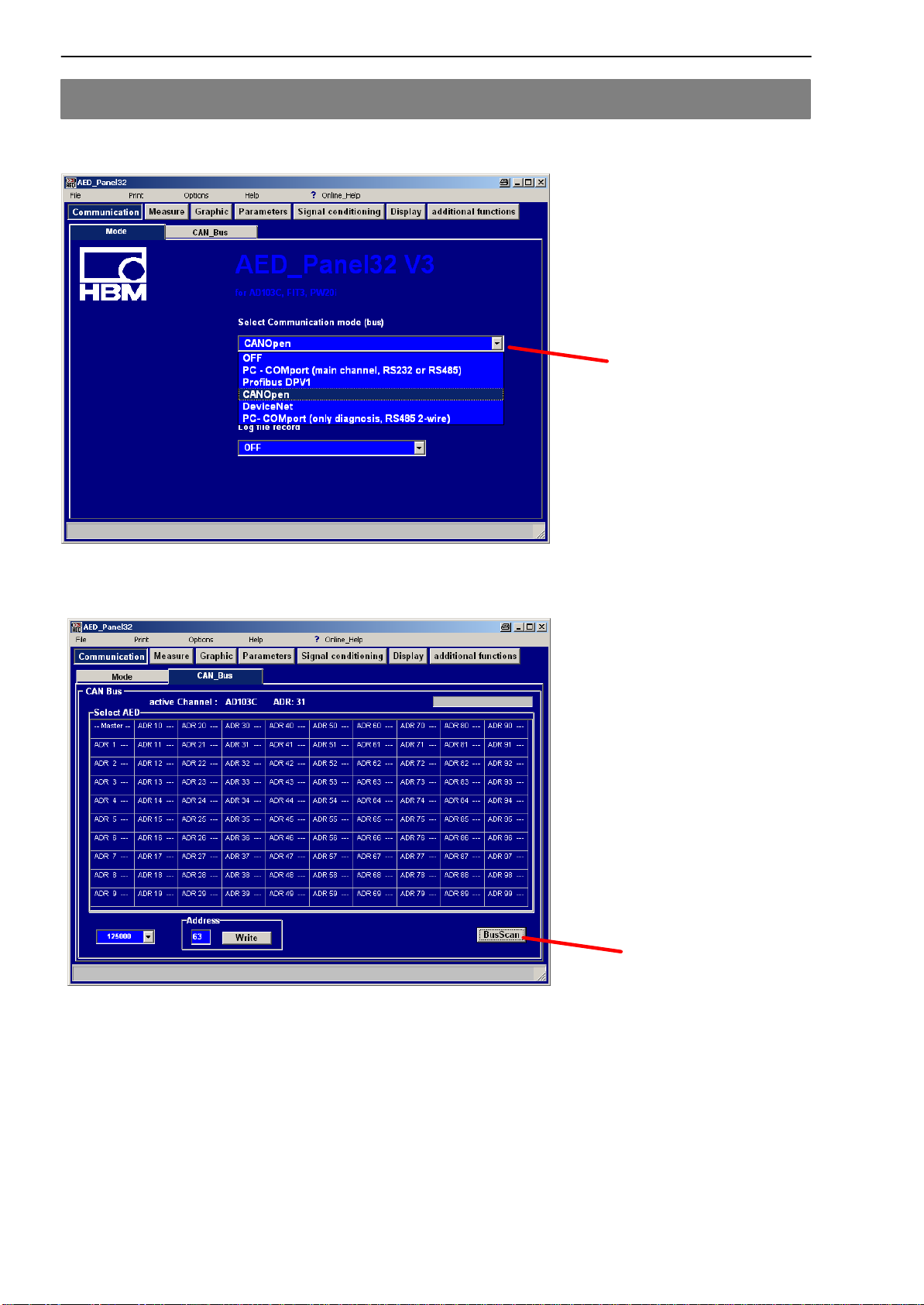
DStarten Panel-Programm
DAuswahl der CAN- / DeviceNet- / Diagnose Verbindung
DEinstellen der jeweiligen Baudrate
DBusScan ausführen, wenn Verbindung OK, ist Adresse 63 (default)
leuchtend hinterlegt in der Busübersicht
DWechsel zu den weiteren Menüs des Panel-Programms
6FIT-AED-KI
T
HBM A2022-1.0 de/en
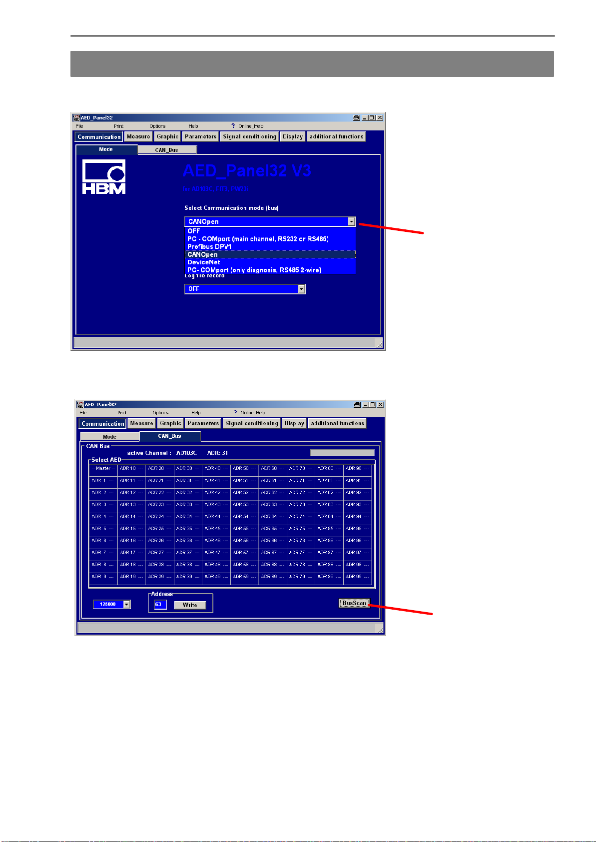
8 Anhang
Einstellungen im Panel-Programm
Auswahl Bussystem CAN / DeviceNet / Diagnose
BusScan (zum Beispiel) CAN-Bus

7
FIT-AED-KIT
HBMA2022-1.0 de/en
1 General
The Starter KIT is used for connecting the FIT (CAN / DeviceNet) or
AED9401A (with AD103C) to a PC.
It is intended for initial startup in the laboratory environment only and must
not be used in industrial environments.
The Starter KIT makes the electrical connection to the PC
(CAN bus / DeviceNet / Diagnosis bus).
For the AED / FIT safety regulations, please refer to the appropriate operating
manual.
2 Starter KIT functions
DDirect connection of the PEAK-USB adapter for the CAN bus/DeviceNet
DBus termination resistor (120 Ω) for the CAN bus
DConnection of the diagnosis bus (RS-485 2-wire) to a PC-COM port
(RS-232), in addition, the Starter KIT includes a level converter (RS-485;
RS-232)
DBus termination resistor (2 x 2 kΩ) for the diagnosis bus
D2 buttons for the IN1/IN2 control inputs of the AED / FIT
D4 LEDs for the OUT1…4 control outputs of the AED / FIT
DPower supply port
DLED for 24 V voltage supply
3 Scope of delivery
DStarter KIT card
DPower supply (100…240 VAC, 24 VDC output, 1.25 A)
DPEAK-USB adapter
DConnection cable (SUB-D9)
D1-FIT-AED-DOC system CD (operating manuals, Panel software)
DThis operating manual
The connection cable (SUB-D9) can either be used for connecting the diagno-
sis bus to the PC-COM port or as a connection cable between the PEAK-USB
adapter and the Starter KIT.
8FIT-AED-KI
T
HBM A2022-1.0 de/en
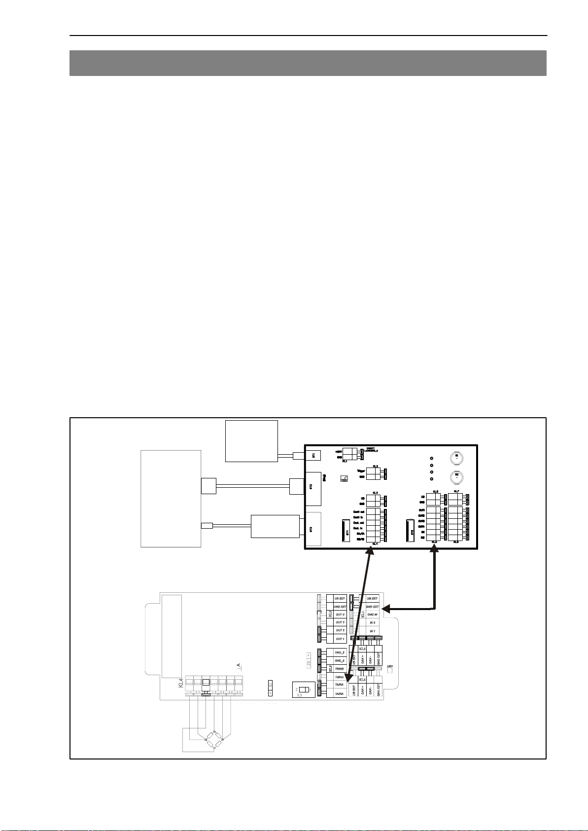
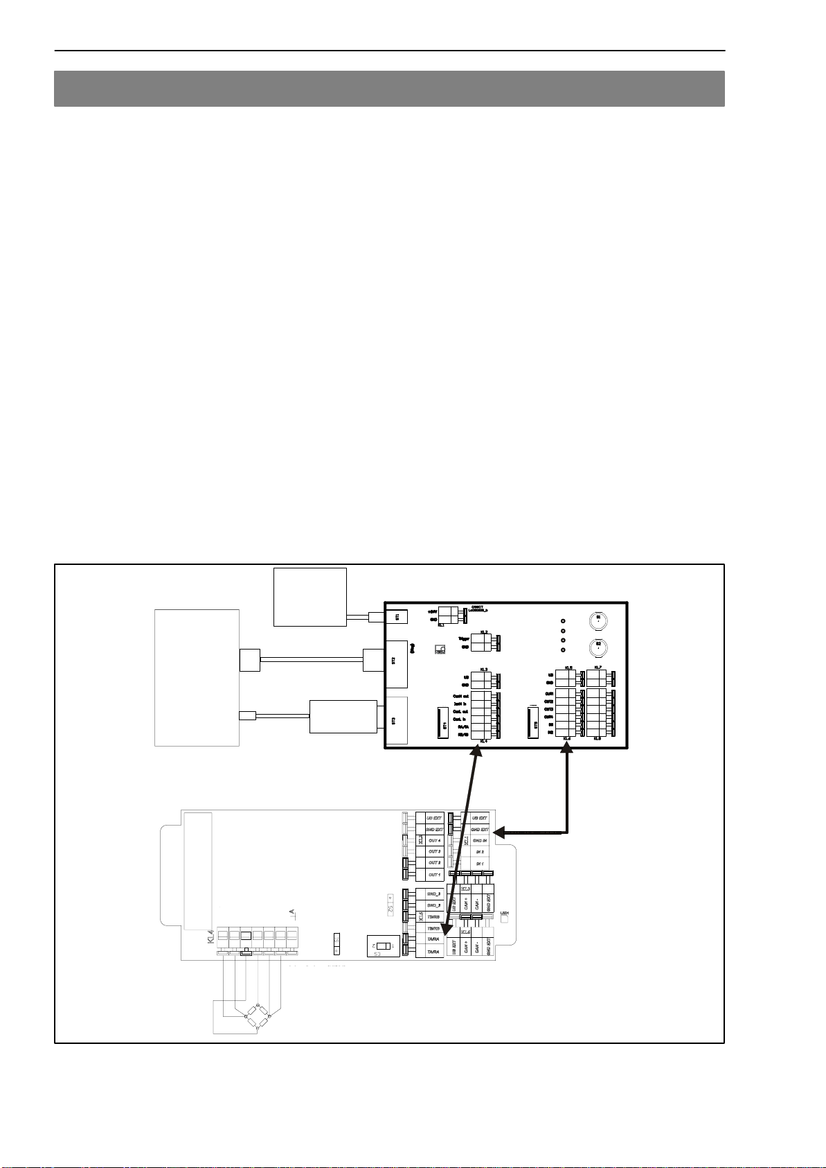
4 Diagram for startup
For the pin assignment and similar of the AED / FIT, please refer to the appro-
priate operating manual.
The diagram includes the below components:
DPower supply
DPC with USB and COM port, with AED_Panel32 (V3.x.x) software installed
DPEAK-USB adapter for the CAN bus / DeviceNet)
DSUB-D9 connection cable (for connecting the diagnosis bus)
DAED9401A with AD103C or FIT with CAN bus / DeviceNet
DTransducer for AED9401A
DStarter KIT card
The AED / FIT is supplied by the power supply of the Starter KIT.
The PEAK converter is supplied by the USB port of the PC.
The designations of the terminals (UB, GND, OUT1…4, IN1, IN2, CANH,
CANL) are identical to those of the AED / FIT and have to be connected di-
rectly.
The CANH_out and CANH _in and CANL_out and CANL_in ports respecti-
vely have been connected to each other in the AED / FIT.
CAN+
UB
RA/TA
RB/TB
GND OUT 1 OUT 1
GND GND
UB
OUT 2 OUT 2
OUT 3 OUT 3
OUT 4 OUT 4
IN1 IN1
IN2 IN2
CAN−
FIT
Kabel1/
cable 1
FIT
Kabel2/
cable 2
PC
Power
supply
24 VDC
Cable
(SUB-D9)
COM1
USB PEAK-
Adaptor
Cable 2
digital I/O, 8 wires
Cable 1
CAN-Bus, Diagnosis-Bus,
UB / GND, 8 wires
AED9401A
AD103C
Load cell
BU 3
GN 3’
RD 4
WH 1
GY 2’
BK 2
Color code (HBM)
BU = blue GN = green
RD = red WH = white
GY = grayBK = black
Transducer / Load cell
OUT1
OUT2
OUT3
OUT4 IN2
IN1
STARTERKIT
1-FIT-AED-KIT
RS232
CAN
FIT
Cable 1
RED
FIT
Cable 2
RED
Fig.1: Connecting the AED9401A to the Starter KIT

9
FIT-AED-KIT
HBMA2022-1.0 de/en
CAN+
UB
RA/TA
RB/TB
GND OUT 1 OUT 1
GND GND
UB
OUT 2 OUT 2
OUT 3 OUT 3
OUT 4 OUT 4
IN1 IN1
IN2 IN2
CAN−
FIT
Kabel1/
cable 1
FIT
Kabel2/
cable 2
PC
Power
supply
24 VDC
COM1
USB
Cable
(SUB-D9)
PEAK-
Adaptor
Cable 2
digital I/O, 8 wires
Cable 1
CAN-Bus,
Diagnosis-Bus,
UB / GND, 8 wires
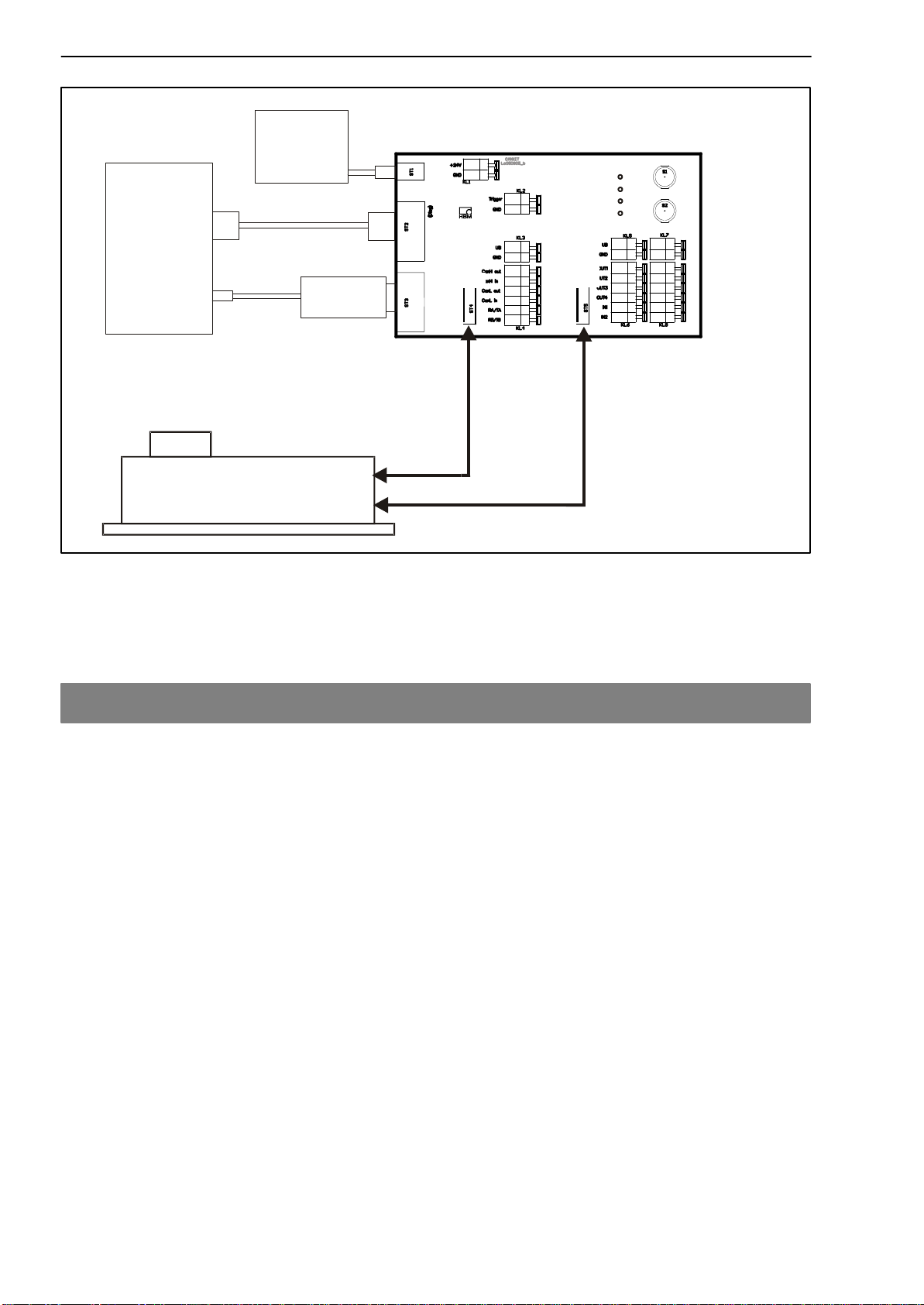
Connection:
Connect red wire with
the RED terminal
FIT)
FIT
Cable 1
FIT
Cable 2
RED RED
OUT1
OUT2
OUT3
OUT4 IN2
IN1
Fig.2: Connecting the FIT to the Starter KIT
The CANH_out and CANH _in and CANL_out and CANL_in ports respecti-
vely have been connected to each other in the FIT.
5 AED9401A and AD103C settings
These settings have to be made once in the AED9401A basic device and in
the AD103C.
AED9401A basic device settings (see operating manual):
DSelect CAN bus or DeviceNet (DIL switch)
DCAN bus disconnection OFF
AD103C settings (default):
DCAN bus address 63 / DeviceNet address 63
DCAN baud rate 125000
DDiagnosis address (ADR = 31, baud rate 38400)
AD103C settings can be changed using the AED_Panel32 (Version 3.x.x) Pa-
nel software.

10 FIT-AED-KI
T
HBM A2022-1.0 de/en
6 FIT settings
Parameters are stored in the FIT in a power failsafe manner.
FIT settings (default):
DCAN bus address 63 / DeviceNet address 63
DCAN baud rate 125000
DDiagnosis address (ADR=31, baud rate 38400)
FIT settings can be changed using the AED_Panel32 (Version 3.x.x) Panel
software.
7 Startup
DConnect the transducer to the AED9401A
DConnect AED / FIT to the Starter KIT
DStart Panel software
DSelect CAN / DeviceNet / Diagnosis communication mode
DSet appropriate baud rate
DRun BusScan; if connection is OK, address 63 (default)
is displayed in the bus survey on a light background
DSelect other dialog menus of the Panel software
11
FIT-AED-KIT
HBMA2022-1.0 de/en
8 Annex
Panel software settings
Select CAN / DeviceNet / Diagnosis communication mode
BusScan (for example) CAN bus

Änderungen vorbehalten.
Alle Angaben beschreiben unsere Produkte in allgemeiner Form.
Sie stellen keine Beschaffenheits- oder Haltbarkeitsgarantie im
Sinne des §443 BGB dar und begründen keine Haftung.
A2022-1.0 de/en
Modifications reserved.
All details describe our products in general form only.They are
not to be understood as express warranty and do not constitute
any liability whatsoever.
Hottinger Baldwin Messtechnik GmbH
Postfach 10 01 51, D-64201 Darmstadt
Im Tiefen See 45, D-64293 Darmstadt
Tel.: +49 06151 803-0 Fax: +49 06151 8039100
Table of contents
Languages:


