HBM ML71BS6 User manual
Operating Manual
English
ML71BS6

Hottinger Baldwin Messtechnik GmbH
Im Tiefen See 45
D-64293 Darmstadt
Tel. +49 6151 803-0
Fax +49 6151 803-9100
www.hbm.com
Mat.: 7-2002.0572
DVS: A00851_03_E00_02 HBM: public
06.2018
EHottinger Baldwin Messtechnik GmbH.
Subject to modifications.
All product descriptions are for general information only.
They are not to be understood as a guarantee of quality or
durability.

ML71BS6 A00851_03_E00_02 HBM: public 3
English
1 Safety instructions 4........................................
2 Markings used 6............................................
2.1 The markings used in this document 6..........................
2.2 Symbols on the product 6.....................................
3 Introduction 7..............................................
4 Connections 8..............................................
4.1 Pin assignment 8............................................
5 Front panel 9...............................................
6 Parameterization 10..........................................
6.1 Settings CAN1 /CAN2 10......................................
6.1.1 Panel output signals CAN 1 12.................................
7 Menu structure in set‐up mode 15............................
8 CAN protocol 16.............................................
8.1 Measurement signal transmission 16............................
8.1.1 Absolute values in Float 16.....................................
8.1.2 In digits as Long 16...........................................
8.1.3 In digits as Word 16...........................................
8.1.4 Identifier assignment 17.......................................

Safety instructions
4A00851_03_E00_02 HBM: public ML71BS6
1 Safety instructions
Use in accordance with the regulations
The ML71BS6 CAN bus module is to be used exclusively for measurement
tasks and directly related control tasks. Use for any purpose other than the
above shall be deemed to be not in accordance with the regulations.
To ensure safe operation, the device may only be operated in accordance with
the information given in the Operating Manual. It is also essential to comply
with the legal and safety requirements for the application concerned during
use. The same applies to the use of accessories.
General dangers of failing to follow the safety instructions
The ML71BS6 CAN bus module complies with the state of the art and is
fail‐safe. The device may give rise to further dangers if it is inappropriately
installed and operated by untrained personnel.
Any person instructed to carry out installation, commissioning, maintenance or
repair of the device must have read and understood the Operating Manual and
in particular the technical safety instructions.
Remaining dangers
The scope of performance and supply of the ML71BS6 only covers part of the
range of measurement technology. In addition, equipment planners, installers
and operators should plan, implement and respond to the safety engineering
considerations of measurement technique in such a way as to minimise
remaining dangers. Prevailing regulations must be complied with at all times.
There must be reference to the remaining dangers connected with
measurement technique.
Working safely
Error messages must only be acknowledged when the cause of the error has
been removed and no further danger exists.
The device complies with the safety requirements of DIN EN 61010‐Part 1
(VDE 0411‐Part 1); Protection Class I.

Safety instructions
ML71BS6 A00851_03_E00_02 HBM: public 5
To ensure adequate immunity from interference, use only Greenline shielded
ducting (see HBM offprint ”Greenline shielding design, EMC‐compliant measur
ing cable; G36.35.0)
Conversions and modifications
No modifications that affect the design or the technical safety of the ML71BS6
CAN bus module may be carried out without our express agreement. Any
modification shall exclude all liability on our part for any resulting damage.
In particular any repair or soldering work on motherboards is prohibited. When
exchanging complete modules, use only original parts from HBM.
Qualified personnel
This instrument must only to be installed and used by qualified personnel,
strictly in accordance with the technical data and the safety requirements and
regulations listed. It is also essential to comply with the legal and safety
requirements for the application concerned during use. The same applies to
the use of accessories.
Qualified personnel means persons entrusted with the installation, assembly,
commissioning and operation of the product who possess the appropriate
qualifications for their function.
Maintenance and repair work on an open device with the power on must only
be carried out by trained personnel who are aware of the danger involved.
Markings used
6A00851_03_E00_02 HBM: public ML71BS6
2 Markings used
2.1 The markings used in this document
Important instructions for your safety are specifically identified. It is essential to
follow these instructions in order to prevent accidents and damage to property.
Symbol Significance
Notice This marking draws your attention to a situation in
which failure to comply with safety requirements can
lead to damage to property.
Important
This marking draws your attention to important
information about the product or about handling the
product.
Tip
This marking indicates application tips or other
information that is useful to you.
Information
This marking draws your attention to information
about the product or about handling the product.
Emphasis
See….
Italics are used to emphasize and highlight text and
references to other chapters and external documents.
2.2 Symbols on the product
CE mark
The CE mark enables the manufacturer to guarantee that
the product complies with the requirements of the rele
vant EC directives (the declaration of conformity is avail
able at http://www.hbm.com/HBMdoc).

Introduction
ML71BS6 A00851_03_E00_02 HBM: public 7
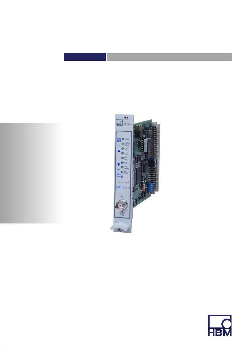
3 Introduction
The ML71BS6 is an MGCplus system module that takes measurement data
from the MGC and outputs it as CAN messages. It records up to 128
measured values per CAN port, scales them and outputs them at the CAN bus.
Two independent CAN interfaces per channel and two different physical layers
(ISO 11898-24V and a ”low‐speed” link based on the Philips TJA1053
transceiver module) are supported.
The measurement data to be transmitted can be selected either by using the
AB22A/AB32 display and control panel or by using the “MGCplus Assistant”
software from HBM.

Connections
8A00851_03_E00_02 HBM: public ML71BS6
4 Connections
4.1 Pin assignment
The CAN bus is connected to the AP71 connection board by a 9‐pin Sub‐D
connector. You can connect two independent CAN field bus systems (female
connectors CAN1 and CAN2). Both the CAN interfaces are used to output the
MGCplus measurement data. Each of the interfaces can be assigned up to 128
measured values.
Connectors (male) CAN1/CAN2
1
5
6
9
CAN Shield
CAN_GND
CAN_L CAN_H
GND
CAN_V+
Physical layer:
High: Standard CAN speeds up to 1MBaud acc. to ISO11898
(24 V dielectric strength).
Low: Low-speed bus for in‐car communication up to 100 kBaud
(CAN_V+ must be connected to 12 V)
Fig. 4.1 CAN connection
Connections
ML71BS6 A00851_03_E00_02 HBM: public 9
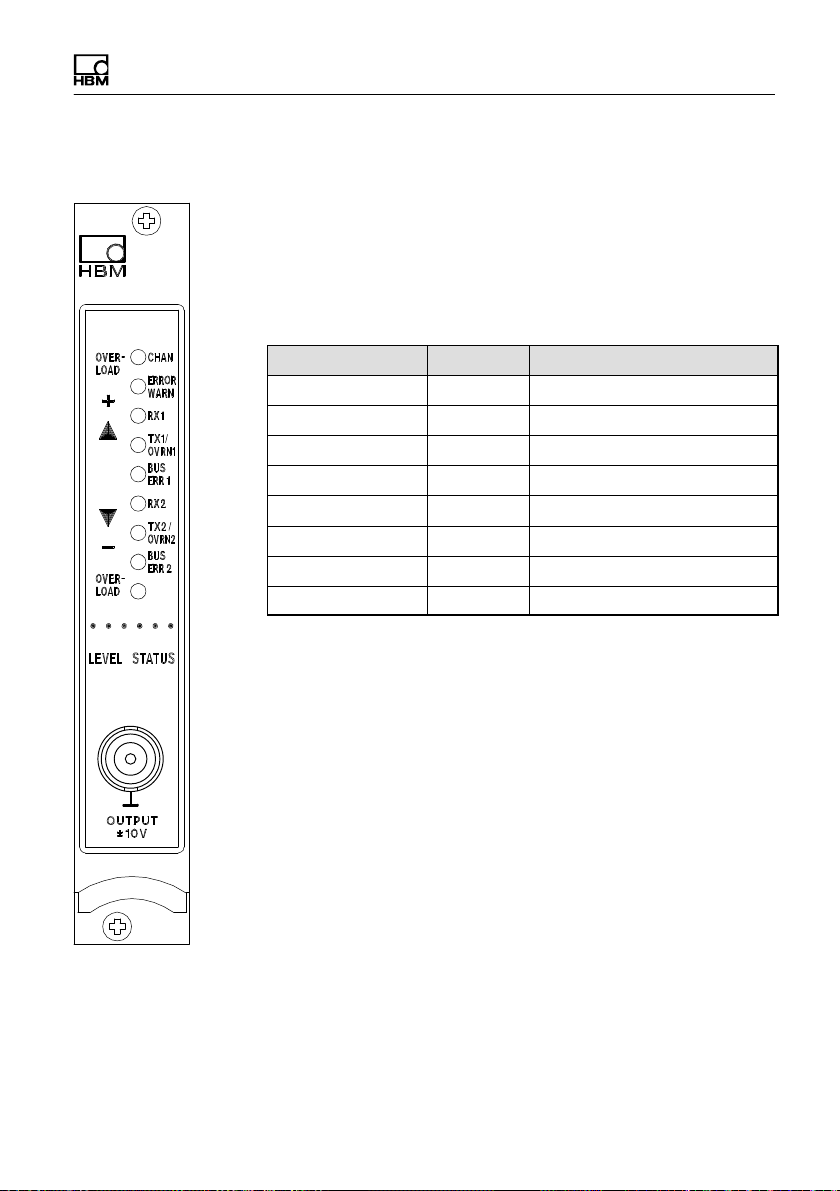
5 Front panel
The front panel LEDs have a dual function:
In Level mode, the signal level at the analogue output is
displayed.
In Status mode, the LEDs are assigned as shown below:
LED caption Colour Meaning in Status mode
CHAN. yellow Channel selected
ERROR/WARN. red error/warning
Rx1 - not used
Tx1/OVRN1 red/yellow CAN protocol transmitted
BUSERR1 red Bus error at CAN1
Rx2 yellow not used
Tx2/OVRN2 red/yellow CAN protocol transmitted
BUSERR2 red Bus error at CAN2
Analog output (BNC connector (female))
Any voltage from -10 V to +10 V can be output through
the female BNC connector by interface command.
ML71
BS6
Connections
10 A00851_03_E00_02 HBM: public ML71BS6
6 Parameterization
6.1 Settings CAN1 /CAN2
The baud rate, the transmission formats, the number of signals and the output
rate of the 1st CAN bus are set here. The same menu is applied
correspondingly to the 2nd CAN bus.
The maximum number of signals for a bus is 128 signals.
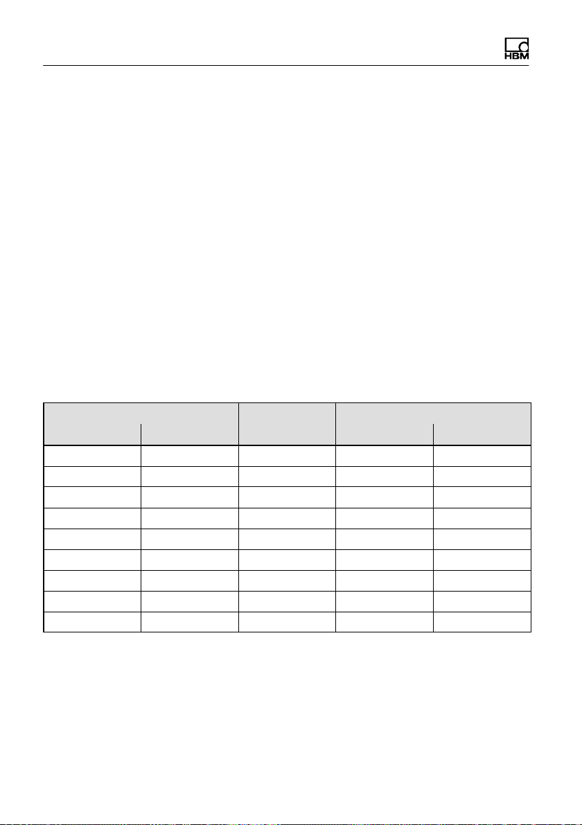
The following output rates are offered for selection depending on the number of
output signals. In the case of the 2nd CAN port, please note that the maximum
possible output rates can only be achieved if no signals have been selected at
CAN port1.
If a selected rate cannot be achieved, the messages will be output as quickly
as possible and an error message will be generated. Transmission will then not
be at a fixed frequency.
Number of signals
Format
Output rate [Hz]
CAN1 CAN2 Port1 Port2
4 4 INT16 2400 800
4 4 INT32 2400 600
4 4 Float32 2400 400
8 8 INT16 1200 800
8 8 INT32 1200 400
8 8 Float32 1200 300
16 16 INT16 600 600
16 16 INT32 600 300
16 16 Float32 600 300
The first ID of a range can be set. The last ID is derived from this and from the
number of signals.
Other manuals for ML71BS6
1
Table of contents
Popular Network Hardware manuals by other brands

Matrix Switch Corporation
Matrix Switch Corporation MSC-HD161DEL product manual

B&B Electronics
B&B Electronics ZXT9-IO-222R2 product manual

Yudor
Yudor YDS-16 user manual

D-Link
D-Link ShareCenter DNS-320L datasheet

Samsung
Samsung ES1642dc Hardware user manual

Honeywell Home
Honeywell Home LTEM-PV Installation and setup guide


