HBM P2VA1 User manual
A1564-5.5 en/de
Pressure transmitter
Drucktransmitter
P2VA1
P2VA2
Mounting Instructions
Montageanleitung

English Page 3 - 21. . . . . . . . . . . . . . . . . . . . . . . . . . . . . . . . . . . . . . . . . . . . . . .
Deutsch Seite 23 - 41. . . . . . . . . . . . . . . . . . . . . . . . . . . . . . . . . . . . . . . . . . . . . .

3
P2VA1, P2VA2
A1564-5.5 en/de HBM
Contents Page
English
Safety instructions 4. . . . . . . . . . . . . . . . . . . . . . . . . . . . . . . . . . . . . . . . . . . . . .
1 Scope of supply 7. . . . . . . . . . . . . . . . . . . . . . . . . . . . . . . . . . . . . . . . . . . . .
2 Application 8. . . . . . . . . . . . . . . . . . . . . . . . . . . . . . . . . . . . . . . . . . . . . . . . . .
3 Mechanical installation 10. . . . . . . . . . . . . . . . . . . . . . . . . . . . . . . . . . . . . . .
4 Electrical connection of the P2VA1/A2 12. . . . . . . . . . . . . . . . . . . . . . . . .
4.1 Electrical signal 14. . . . . . . . . . . . . . . . . . . . . . . . . . . . . . . . . . . . . . . . . .
4.2 TEDS transducer identification 15. . . . . . . . . . . . . . . . . . . . . . . . . . . . .
5 Measuring dynamic pressures 16. . . . . . . . . . . . . . . . . . . . . . . . . . . . . . . .
6 Specifications (to DIN 16086) 17. . . . . . . . . . . . . . . . . . . . . . . . . . . . . . . . .
7 Dimensions 20. . . . . . . . . . . . . . . . . . . . . . . . . . . . . . . . . . . . . . . . . . . . . . . . .

P2VA1, P2VA2
4
A1564-5.5 en/deHBM
Safety instructions
Appropriate use
The P2V pressure transmitter is to be used exclusively for pressure measure
ment tasks and directly related control tasks. Use for any purpose other than
the above shall be deemed to be inappropriate.
In the interests of safety, the device should only be operated as described in
the Operating Manual. It is also essential to observe the appropriate legal and
safety regulations for the application concerned during use. The same applies
to the use of accessories.
We hereby declare that this device conforms to the requirements of Pressure
Directive 97/23/EC, the European Parliament and Council Directive of May 29
1997, which approximates the legal provisions of the Member States concern
ing pressure equipment.
The pressure transmitter is not a safety element within the meaning of its use
as intended. Proper and safe operation of this pressure transmitter requires
proper transportation, correct storage, assembly and mounting and careful
operation.
It is not appropriate for use as an “accessory with a safety function”, in
accordance with the regulations and this must be assessed by the user (within
the meaning of Pressure Equipment Directive 97/23/EC) for the particular situ
ation.
General dangers of failing to follow the safety instructions
The P2V pressure transmitter corresponds to the state of the art and is
failsafe. The device may give rise to further dangers if it is inappropriately
installed and operated by untrained personnel.
Any person instructed to carry out installation, commissioning, maintenance or
repair of the device must have read and understood the Operating Manual
and in particular the technical safety instructions.
Accident prevention
You must make sure that the line is not under pressure when installing or
removing the pressure transmitter.
Remaining dangers
The scope of supply and performance of the transducer covers only a small
area of measurement technology. In addition, equipment planners, installers
and operators should plan, implement and respond to the safety engineering
considerations of pressure measurement technology in such a way as to min
imize remaining dangers. Prevailing regulations must be complied with at all

5
P2VA1, P2VA2
A1564-5.5 en/de HBM
times. There must be reference to the remaining dangers associated with
pressure measurement technology.
Although the P2V is designed for maximum safety, safety engineering regula
tions demand that burst protection is implemented around the transducer.
The transducer must be protected against mechanical loads or knocks.
The resistance of the steel of the measuring body only applies if temperatures
are never allowed to fall below or rise above the limits specified in the data
sheet.
If these temperature limits are exceeded, in the event of fire, for example, the
transducer will be unusable.
A significant change in the zero signal shows that the device has come to the
end of its service life.
Remaining dangers are indicated in this operating manual by the following
symbols:
Symbol: DANGER
Meaning: Maximum danger level
Warns of an imminently dangerous situation in which failure to comply with
safety requirements will result in death or serious physical injury.
Symbol: WARNING
Meaning: Potentially dangerous situation
Warns of a potentially dangerous situation in which failure to comply with
safety requirements can result in death or serious physical injury.
Symbol: CAUTION
Meaning: Potentially dangerous situation
Warns of a potentially dangerous situation in which failure to comply with
safety requirements could lead to damage to property, slight or moderate
physical injury.

P2VA1, P2VA2
6
A1564-5.5 en/deHBM
Symbol: NOTE
Means that important information about the product or its handling is being
given.
Symbol:
Meaning: CE mark
The CE mark enables the manufacturer to guarantee that the product com
plies with the requirements of the relevant EC directives (the Declaration of
Conformity can be found at http://www.hbm.com/HBMdoc).
Conversions and modifications
The P2V/xxx pressure transmitter must not be modified from the design or
safety engineering point of view except with our express agreement. Any
modification shall exclude all liability on our part for any damage resulting
there from.
Qualified personnel
The pressure transmitter is only to be installed and used by qualified person
nel strictly in accordance with the technical data and with the safety rules and
regulations which follow. It is also essential to observe the appropriate legal
and safety regulations for the application concerned during use. The same
applies to the use of accessories.
Qualified personnel means persons entrusted with the installation, assembly,
commissioning and operation of the product, who possess the appropriate
qualifications for their function.
Recalibration and repair
When you send the transducer back to HBM for calibration or repair, please
specify which pressure medium is being used. It is always possible that resid
ual medium could be trapped in the measuring aperture. We need this inform
ation so that we can take appropriate action and choose the correct cleaning
agent, where necessary. If we do not know the media, we may have to refuse
to calibrate or repair.

7
P2VA1, P2VA2
A1564-5.5 en/de HBM
1 Scope of supply
The scope of supply for the standard version includes:
•1 x pressure transducer
voltage output:
Order No.: 1-P2VA1/100...7000 bar or
current output:
Order No.: 1-P2VA2/100...7000 bar
•1 x 5 m cable, female cable connector, M12x1 with shielding,
5-pin. Polyurethane
Order No.: 1-KAB166-5
•For pressure transducer 1-P2VA1/100...2000 bar or
1-P2VA2/100...2000 bar in addition:
1 pack with 2 x 58-degree tapered seals with retaining spring1)
Order No.: 2-9278.0371
•1 x Mounting Instructions
Options to be ordered:
Connection adapter for measuring ranges less than 3000 bar
•Connection adapter G1/4"external thread, M20x1.5 external thread
Order No.: 1-Adapt-G1/4-M20
•Connection adapter G1/4"external thread, G1/2"external thread
Order No.: 1-Adapt-G1/4-G1/2
•Pack with 2 x 58-degree tapered seals with retaining spring 1)
Order No.: 2-9278-0371
•5 m cable, female cable connector, M21x1 with shielding,
5-pin. Polyurethane
Order No.: 1-KAB166-5 2)
•20 m cable, female cable connector, M21x1 with shielding,
5-pin. Polyurethane
Order No.: 1-KAB166-20
1) for measuring ranges of 100 bar to 2000 bar
2) as a spare or for an additional need
P2VA1, P2VA2
8
A1564-5.5 en/deHBM
2 Application
In the measuring system, the P2V transducer corresponds to HBM's proven
passive strain gage absolute pressure transducers, with a measuring body
made from one piece of material. A high-quality analog sensor amplifier and a
digital control for signal correction are also integrated in the enclosure.
All that is seen of this circuitry on the outside is what looks like an active
sensor output with 0.5 to 10 volts (or a 3-wire current output of 4 to 20 mA.) .
The additional microcontroller monitors the sensor temperature and the cur
rent pressure and generates correction signals, so that systematic sensor
errors such as temperature coefficients and the linearity deviation can be
compensated for internally. The individual adjustment and correction data can
be transferred to the transducer during production. HBM's TEDS digital identi
fication system is also available (compatible with the 1-wire EEPROM
DS2433, MikroLan from Messrs Maxim / Dallas).
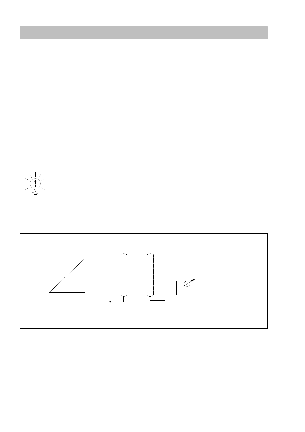
NOTE:
The 0 V power supply (pin 3) and 0 V output (pin 2) lines are
linked internally.
+UB
+Uout/Iout
0 V
P
U
Enclosure Enclosure
Fig. 2.1: Electrical connection diagram

9
P2VA1, P2VA2
A1564-5.5 en/de HBM
Blow-off opening:
The transducer housing features a blow-off opening under the blue label (see
figure):
Blow-off opening
This safety device enables overpressure to be reduced in a controlled way in
the event of bursting of the sensing element. This prevents overloading of the
sensor housing. The blow-off opening opens at approx. 10 bar.
P2VA1, P2VA2
10
A1564-5.5 en/deHBM
3 Mechanical installation
CAUTION
Before installing the P2V, check that the threaded connector and
the thread in its mating component are sound and without
burrs. The parts must be easy to join together.
The pressure transducer can be screwed in wherever required. If the transducer
is used to measure dynamic pressure characteristics in liquids, it should be
installed with the pressure connection pointing upward, so that it not possible for
an air cushion to build up in the measuring tube that could, for example, heat up
unacceptably in the event of adiabatic effects as a result of dynamic loads.
Transducers with measuring ranges of 100 ... 2000 bar are connected with their
G1/4"external thread pressure connection. A 58°tapered seal made of 1.4301
corrosion-resistant material is supplied for this purpose.
The G1/4"pressure connection thread with the tapered seal is suitable for the
usual 17 mm hole depth and a drilled diameter of 4 mm (with a margin of
between 0 and 0.5x45°, also see Specifications).
The tapered seal is fixed accurately and securely in the measuring aperture of
the transmitter by means of the small, stainless steel retaining spring that is
among the items supplied for each seal. The device can thus be fitted and
sealed extremely efficiently.
Transducers with measuring ranges of 3000 bar and higher are connected with
their M16x1.5 external thread pressure connection directly to conventional high
pressure pipes with their 58°taper.
CAUTION:
During installation, screwing torque must not be applied over the
enclosure or the cable entry. Wrenches (SW 24) must be used to
screw-fasten the pressure transmitter. The permissible tightening
torque for measuring ranges 100 ... 2000 bar is 30 Nm; for measur
ing ranges 3000 and 7000 bar, the permissible tightening torque is
30 ... 50 Nm

11
P2VA1, P2VA2
A1564-5.5 en/de HBM
DANGER:
Before removing the P2V pressure transmitter, you must check that
the line is not pressurized.
P2VA1, P2VA2
12
A1564-5.5 en/deHBM
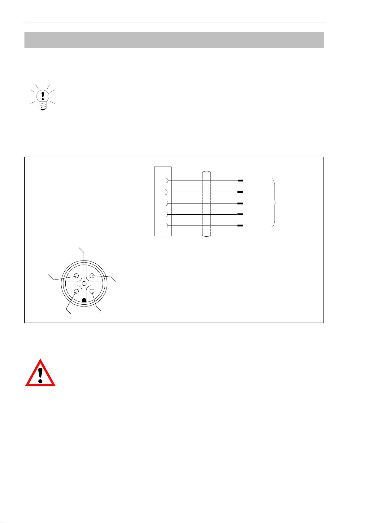
4 Electrical connection of the P2VA1/A2
An external amplifier is connected to the P2V in accordance with Fig. 4.1.
NOTE:
The inputs and outputs of the P2V are protected against short cir
cuits and reverse polarity.
1
3
2
Supply voltage 15 to 30 V DC 1)
Transducer identification
TEDS DATA
Supply voltage 0 V 2)
Output 0 V
Output 0.5 to 10 V (4 to 20 mA for the P2VA2)
5
brown
blue
black
white
gray
4
Connections 2 and 3 are internally linked.
3
5
4
12
1) Operating on a SELV circuit (separated extra-low
voltage)
2) also ground for TEDS
Connection
cable wire
assignments
Fig. 4.1: Pin assignment of the P2V
CAUTION:
Using the TEDS memory: Because of the electrical specifications,
voltages > 6 V must never be applied to the TEDS memory. Never
connect the supply voltage of the P2V with TEDS pin 5. This
would destroy the memory.

13
P2VA1, P2VA2
A1564-5.5 en/de HBM
If the P2V is connected with the HBM MGCplus amplifier system, the connec
tion is made via AP01i, as shown in Fig. 4.2.
2
1
8
9
Cable wire colors: wh= white; bk= black; bu= blue; rd= red; ye = yellow; gn= green; gr= gray
AP01i
(ML01B)
bn
wh
bu
bk
gy
1
2
3
4
5
15
4
8
9
15
P2VA1
15 V
0 V (TEDS)
0.5 - 10 V
TEDS
6
Connector side view
of transducer
1
24
5
3
2
1
8
9
AP01i
(ML01B)
bn
wh
bu
bk
gy
1
2
3
4
5
6
4
5
9
15
P2VA2
15 V
0 V (TEDS)
4 ... 20 mA
TEDS
Connector side view
of transducer
1
24
5
3
Voltage output
Current output
Fig. 4.2: Connection with TEDS to AP01i
P2VA1, P2VA2
14
A1564-5.5 en/deHBM
NOTE:
The 0 V power supply (pin 3) and 0 V output (pin 2) lines are
linked internally.
The transducer is designed for direct voltage operation (15 to 30 volts).
The circuit is intended for operating with a separated extra-low voltage (SELV
circuit). It is not intended for connection to a dc network in accordance with
EN 61010-1.
Should the equipment be operated on a dc voltage network, additional pre
cautions must be taken to discharge excess voltages.
NOTE:
The P2V meets EMC guideline requirements (a condition of the
transducer being granted the CE mark).
To prevent measured value errors when there is heavy high-fre
quency interference, a shielded connection cable with a metal
female cable connector must be used, with the cable shielding
connected to the entire surface of the female cable connector. The
enclosed HBM connection cable meets this requirement.
4.1 Electrical signal
The output signal of the P2VA1 pressure transmitter at 0 pressure is 0.5 V, for
the P2VA2 pressure transmitter, it is 4 mA.
The output signal of the P2VA1 pressure transmitter at nominal (rated) pres
sure is 10 V and for the P2VA2 it is 20 mA. Accordingly the output signal span
(sensitivity) for the P2VA1 is 9.5 V and for the P2VA2, 16 mA.
The displayed pressure is calculated from:
P2VA1: Pabs = ( Uout -0.5 V ) * nominal (rated) pressure / 9.5 V
P2VA1: Pabs = ( Uout -4 V ) * nominal (rated) pressure / 16 mA

15
P2VA1, P2VA2
A1564-5.5 en/de HBM
4.2 TEDS transducer identification
At connection 5 (to ground at 3), there is a digital identification system avail
able. The basis for this is a 1-wire EEPROM DS2433, from Messrs Maxim/
Dallas.
TEDS stands for “Transducer Electronic Data Sheet”. An electronic data sheet
is stored in the transducer as defined in the IEEE 1451.4 standard, making it
possible for the measuring amplifier to be set up automatically. A suitably
equipped amplifier imports the transducer characteristics (electronic data
sheet), translates them into its own settings and measurement can then start.
HBM provides you with the TEDS Editor for storing your data. This is included
in the software for the MGCplus Setup Assistant.
The Editor also makes it possible to manage the different user rights, to pro
tect the fundamental transducer data from being inadvertently overwritten.
Contents of the TEDS memory as defined in IEEE 1451.4:
The information in the TEDS memory is organized into templates which are
prestructured to store defined groups of data in table form. Only the entered
values are stored in the TEDS memory itself.
The amplifier firmware assigns the interpretation of the respective numerical
values. This places a very low demand on the TEDS memory.
The memory contents are divided into four areas:
Area 1:
An internationally unique identification number (cannot be changed).
Area 2:
The base area (basic TEDS), to the configuration defined in standard
IEEE1451.4. The transducer type, the manufacturer and the transducer serial
number are contained here.
Area 3:
Data specified by the manufacturer are contained in this area:
The data specifies
- the transducer type,
- the measured quantity,
- the electrical output signal,
- the required excitation.
Area 4:
The actual user can modify the last of these areas with, for instance:
- a short comment in text form,
- filter settings,
- zero value.

P2VA1, P2VA2
16
A1564-5.5 en/deHBM
Example:
The TEDS content of sensor P2VA1/500 bar with ident. no. 081310277, man
ufactured in August 2004
TEDS
Manufacturer HBM
Model P2V (voltage output)
Version letter
Version number 8
Serial number 1310277
Template: High Level Voltage Output sensor
Transducer Electrical Signal Type Voltage Sensor
Minimum Pressure 0.000 Pa
Maximum Pressure 50.000M Pa
Minimum Electrical Value 500.00000m V
Maximum Electrical Value 10.00000 V
Mapping Method Linear
AC or DC Coupling DC
Output Impedance of the Sensor 10.00k Ohm
Transducer Response Time 1.0000000u sec
Excitation Level (Nominal) 24.0 V
Excitation Level (Minimum) 15.0 V
Excitation Level (Maximum) 30.0 V
Excitation Voltage Type DC
Maximum current draw at nominal excita
tion level 25.12m A
Calibration Date 3-Aug-2004
Calibration Initials HBM
Calibration Period (Days) 0 days
Measurement location ID 0
Template: HBM Channel name
Channel name P2VA1 / 500 bar
5 Measuring dynamic pressures
During dynamic loading, the maximum pressures should not be greater than
the nominal pressure.
The transducers are designed for these loads, but the actual conditions from
the operating load and the typical spread require safety measures against the
transducer bursting.
Calibration related to static pressures is also applicable when measuring
dynamic pressures.

17
P2VA1, P2VA2
A1564-5.5 en/de HBM
6 Specifications (to DIN 16086)
Type P2VA1 (output signal in V) 1)
P2VA2 (output signal in mA) 1)
Measuring ranges bar 100 200, 500, 1000,
2000, 3000 5000, 7000
Input quantities
Pressure type Absolute pressure
Accuracy class 0.2 0.3
Initial value bar 0
Operating range at reference temperature %0 to approx. 110
%0 to approx. 105
Overload limit at reference temperature % 150
Test pressure % 200 150
Dynamic loading
Permissible pressure
Permissible vibration amplitude
(dyn. load according to DIN 50100)
%
%100
70
Dead volume approx. cm30.8
Control volume, approx. mm31.5
Materials from which components in
contact with the measurement media are
made
1.4542, 1.4301
Output characteristics
Transducer identification TEDS
Signal span (sensitivity) V0.5 ...10
mA 4...20 (16)
Zero signal, adjustment tolerance Vt"0.02 t"0.010 "0.020
(factory) mA "0.032 t"0.016 "0.032
Sensitivity tolerance Vt"0.02 t"0.010 "0.020
mA "0.032 t"0.016 "0.032
Maximum signal V 10.5
mA 21.6
Effect of temperature on the zero signal
in the nominal (rated) excitation voltage
range per 10K, by reference to the nominal
(rated) sensitivity
% /
10K 0.2
Effect of temperature on sensitivity in
the nominal (rated) excitation voltage range
per 10K, by reference to the actual value
% /
10K 0.2
Characteristic curve deviation (start set
ting)
%0.3
Repeatability according to DIN 1319 %t"0.05
Cut-off frequency
-3 dB
-1 dB kHz
kHz 4.5
2
Burden Ω ≥10000 (min.)
3500 (max.)
1) normal type: P2VA1; italics: P2VA2

P2VA1, P2VA2
18
A1564-5.5 en/deHBM
Auxiliary energy
Reference voltage
Nominal (rated) range V
V24
15 ... 301)
Effect of the supply voltage
when changing from 15 to 30 V % 0.02
Max. current consumption (for the
P2VA2, excluding loop current) mA +25
Max. power consumption Wt1
t2
Ambient conditions
Reference temperature oC +23
Nominal (rated) temperature range °C0 ... + 70
Operating temperature range °C-20 ... + 85
Storage temperature range °C-40 ... +85
Impact resistance (tested to DIN IEC68)
Impact acceleration m/s21000
Impact duration ms 4
Impact form Half sine wave
Vibration resistance (tested to DIN IEC
68) m/s2150
Mechanical specifications
Measuring ranges bar 100, 200, 500,
1000, 2000 3000, 5000, 7000
Pressure connection G1/4 externally M16 x 1.5 internally
Seal Metallic, edge loading, 58°taper.
For the mounting operation, the seal can be
attached to the transducer.
Transducer mounting The seal can be
attached to the
transducer.
Connect directly to a
high-pressure pipe
with a manipulated
pipe end
Tightening torque, max. Nm 30 30...50
Electrical connection M12 x 1 / 5-pin connector
Mounting position Any, but preferably pressure connection
uppermost for venting purposes
Dimensions
Length (without pres. connection and mating
connector)
Maximum diameter
mm
mm
70
30
approx. 80
30
Hexagon, across flats mm 24
Weight without cable, approx. g 150 200
Degree of protection IP67
1) With P2VA2, the permissible dissipation power is exceeded at maximum operating temperature and maximum excitation voltage.
Therefore, the maximum operating temperature is 70 °C instead of 85 °C with P2VA1.

19
P2VA1, P2VA2
A1564-5.5 en/de HBM
Sealing joint (to customer design)
3000 bar and higher:
M16x1.5 internally: High-pressure screw connector M16x1.5, for example, from
Nova Swiss. The transducer has a relief aperture, which exits in the center of a
hexagonal face.
Less than 3000 bar:
G1/4"externally (using the conical seals 58 degree with retaining spring included
for these measuring ranges): The depth to the root of the line aperture should be
17mm, the thread must be at least 13.5mm long. The diameter of the line aper
ture should be 4mm sharp-edged or with a margin (max. 0.5x45°)of 5mm.
Possible up to 1000 bar:
Under the hexagon, sealing is provided by a Usit ring, 14.7x22x1.5. The ring must
be centered and supported by a recess with a depth of 1.3mm and a diameter of
22.2 "0.1mm.

P2VA1, P2VA2
20
A1564-5.5 en/deHBM
7 Dimensions
P2V 100 bar -2000 bar
Installation
example
Tapered seal
with retaining
spring
Production number
10
Ø3.5
Ø7
58o
Pressure
transmitter
Relief
aperture
Tapered seal
with retaining
spring
approx. 70
Ø30
60o
M12x1
Built-in 5-pin
connector
approx. 60
24 a.f.
G 1/4"
Ø6
13
17
Ø4
G1/4"
Bending radius,
static, 25 mm
Other manuals for P2VA1
1
This manual suits for next models
1
Table of contents
Languages:
Other HBM Transmitter manuals


