HBX SNO-0111 User manual

HBX Control Systems Inc.
Installation Manual
Socket and Cover Plate 0111
Snowmelt Sensor 0110

HBX Snowmelt Sensor
HBX Snowmelt Sensor
Page 2
TABLE OF CONTENTS
Introduction ............................................................................................ 3
Description ...............................................................................................3
Safety Symbols & Warnings ................................................................... 3
Receipt & Inspection .............................................................................. 3
Technical Data ........................................................................................4
Dimensions ...............................................................................................4
Installation and Wiring .............................................................................5-8
Installation ..................................................................................................5
Wiring .........................................................................................................7
Testing and Troubleshooting Procedure..................................................9-10
SNO-0110 - Testing .....................................................................................9
SNO-0110 - Troubleshooting .....................................................................9-10
Warranty Information ................................................................................11
Index

HBX Snowmelt Sensor
HBX Snowmelt Sensor
© HBX Control Systems Inc. 2014 Page 3
RECEIPT & INSPECTION
The SNO-0110/SNO-0111 has gone through rigorous
quality control tests at the factory before shipment.
After receipt and before installation perform the
following checks:
Receipt
After receiving, inspect the unit for any possible
physical damage that may have occurred during
transportation.
Inspection
After unpacking the unit make sure the boxes
contain:
SNO-0110 Package:
• Optical snowmelt sensor
• 30 meters of 22AWG 2 pair shielded cable
• 4 x Stainless steel 4 x 25mm machine screws
• 3 meters Universal Sensor
SNO-0111 Package:
• Sensor socket
• Cover plate (dud sensor)
• 4 x Stainless steel 4 x 25mm machine screws
• Remote Slab Sensor
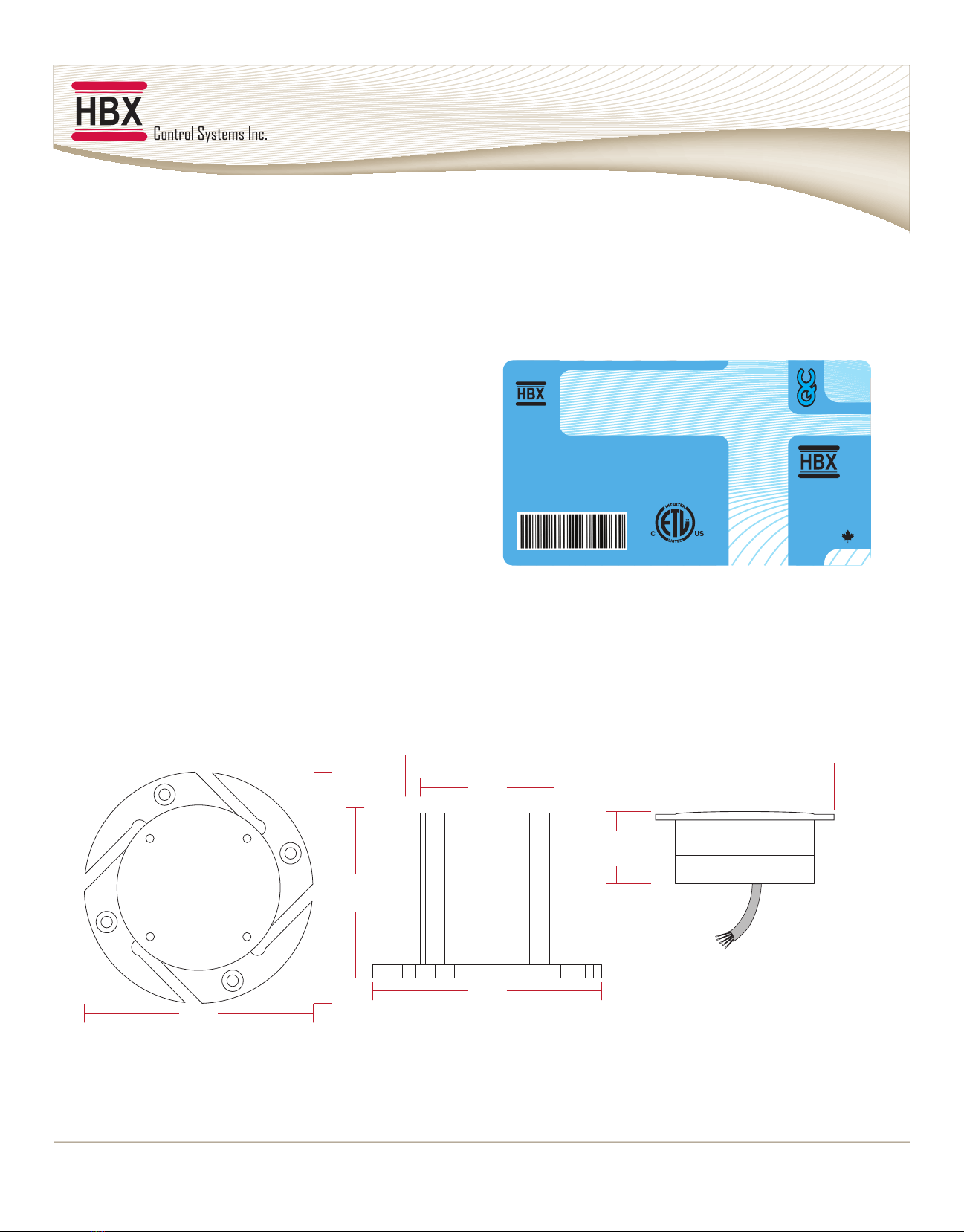
DESCRIPTION
Together the SNO-0110 (sensor & cable) and the
SNO-0111 (socket and cover plate) make up the
sensor portions of the HBX Snowmelt System. The
SNO-0110 snow/ice sensor is an optical design that
is capable of sensing snow conditions. This allows
the user to set a preferred starting condition for
the snowmelt system. The SNO-0110 is design to
be mounted in the slab however because of the
optical design it can also be remotely installed.
The SNO-0111 socket and cover plate allows for the
concrete, asphalt, etc. to be poured prior to the
installation of the Snowmelt Control, and the SNO-
0110 snow/ice sensor.
Only suitably qualied individuals with
formal training in electrical and HVAC
controls should attempt the installation
of this equipment. Incorrect wiring
and installation will affect the warranty
provided with this unit. Wiring must be
completed in accordance with the
codes and practices applicable to the
jurisdiction for the actual installation.
SAFETY SYMBOLS & WARNING
Point of Interest
This point claries pertinent information,
or brings your attention to an action
that may have adverse effects on the
installation process.
Moderate Hazard
This action may cause personal injury or
have adverse effects on the installation
process if handled incorrectly.
Drawing Reference
Refer to the specied electrical or
mechanical drawing at the back of the
manual.
INTRODUCTION
This manual will help with the installation, parameter setting, troubleshooting and general maintenance
requirements for the snowmelt sensor, socket and cover plate. To guarantee the safe and reliable operation
ofyoursnowmeltsystem,youmustrstreadthismanualindetailandtakeparticularnotetoanyandall
warnings.
HBX SNO-0111/ SNO-0100 SNOWMELT SENSOR/ SOCKET AND COVER PLATE

HBX Snowmelt Sensor
HBX Snowmelt Sensor
Page 4
Nameplate Information:
The exterior label contains specic information
uniquetoyourHBXSnowmeltSensorandidenties
some of the basic features. The label displays the
serial number which will match the serial number
on the SNO-XXXX Control, the lot number, the bar
code and the product’s ETL number.
TECHNICAL DATA AND DIMENSIONS
TECHNICAL DATA
Materials:
Polycarbonate and brass
Weight:
0.45 KG (1.00 lb)
Socket Dimensions:
140mm W x 103mm H x 140mm D
Sensor Dimensions:
100mm W x 38mm H x 100mm D
ETL Listings:
Meets CSA C22.2 No. 24
Meets UL Standard 873
ETL Control No. 3068143
DIMENSIONS
82 mm
(3.23 in)
140 mm
(5.51 in)
140 mm
(5.51 in)
140 mm
(5.51 in)
103 mm
(4.06 in)
100 mm
(3.94 in)
Side ViewTop View
SNO-0110
SnowMelt Sensor
and Cable
SNO-0110
SnowMelt Sensor and Cable
Made In
Canada
3068143
Lot#000000000
Serial #:00000000
Date: 00-00-0000
V1.02
100 mm
(3.94 in)
38 mm
(1.50 in)

HBX Snowmelt Sensor
HBX Snowmelt Sensor
© HBX Control Systems Inc. 2014 Page 5
INSTALLATION AND WIRING
INSTALLATION:
1. Slab Sensor Location
Installing the sensor at the correct location in the slab is
critical for a properly functioning snow/ice melting system.
The sensor should be located where snowfall is normal and
not affected by surrounding buildings. Also, the sensor must
not be installed where standing water could accumulate
on its surface.
The sensor location should also be halfway between the
twoheatingpipesthatareinstalledintheslab(seegure
1). There is a thermistor built into the sensor that senses the
slab temperature at all times. Keeping the sensor away
from pipes in the slab ensures the accurate operation of
your snow/ice melting system.
a) Mounting the Socket and cover plate
When mounting the socket and cover plate in the snowmelt
slab use rebar mounted in the soil below to level the socket
and cover plate so that the cover plate is level with the
nishedgradeofthesnowmeltingsurface(seegure2).
When the socket and cover plate are level use a screw to
tightenthesocketontotherebar.(seegure3)
Failure to mount the socket properly may result in
incorrect or faulty sensor readings.
i) Ramp Mounting
The socket and cover plate can also be mounted on a
ramp. Make sure to locate the socket and cover plate near
the bottom of the ramp. This will allow for proper ice melting
whenthemeltedsnowowsdown(seegure4).
ii) Brass Plugs
On the socket there are 4 brass plugs. These plugs are
designed to make contact with the brass ring on the sensor
so the sensor can get proper slab temperatures. Take care
not to press these plugs in or out as they are properly set
at the factory. Manipulation of the plugs may result in the
sensornotttingproperlyinthesocket(seegure5).
Take special care to clean the brass surfaces on the inside
of the socket. Making sure to clean any concrete that may
have accumulated on them. Failure to do so may result in
the sensor not making proper contact and not reading the
slab temperature properly.
Figure 1 - Snowment sensor location
Figure 2 - Leveling the socket and cover plate
Figure 3 - Tightening the socket onto the rebar
Top of Slab
Heating Pipe
Rebar
Underslab
Insulation Compact
Base
Other manuals for SNO-0111
1
This manual suits for next models
1
Table of contents
Other HBX Accessories manuals