HBX WAV-0110 User manual

Page 1
©HBX Control Systems Inc. 2015
Phone: +1 (403) 720-0029 Fax: +1 (403) 720-0054
Email: info@hbxcontrols.com Web: www.hbxcontrols.com
HBX Control Systems Inc.
4516 - 112th Avenue SE
Calgary, AB Canada T2C 2K2
HBX Control Systems Inc.
WAV-0112
WAV-0111
WAV-0110
Installation Manual
WAV-0110
WAV-0111
WAV-0112
Version 1.005

Control Systems Inc.
Comfort
Control
Innovation
HBX WAV-0110 Wireless Outdoor Sensor
Version 1.0
Page 2
Table of Contents
•Introduction 3-5
o Getting Started.......................................................... 3
o Safety Symbols and Warnings................................. 3
o Receiving, Inspection and Storage..........................3
o Description.................................................................4
o Technical Data and Dimensions.............................5
•Installation and Wiring 6-8
o Mounting and Wiring................................................6
o Setting the Dipswitches............................................6
o Initial Setup and Pairing........................................... 7-8
o Verify Wireless Pairing..............................................8
o Battery Life Indicator............................................... 8
o Loss of Communication Mode.............................. 9
o Thermistor Output Curves......................................10
•Warranty Information 11
Table of Contents

HBX WAV-0110 Outdoor Wireless Sensor
Version 1.0
© HBX Control Systems Inc. 2015 Page 3
HBX WAV-0110 WIRELESS OUTDOOR
SENSOR
Introduction
This manual will help with the installation, parameter
setting, troubleshooting and general maintenance
requirements for the Controller. To guarantee the
safe and reliable operation of this Control, you must
rst read this manual in detail and take particular note
to any and all warnings or caution directives prior to
connecting to AC power.
Only suitably qualied individuals with formal training
in electrical and HVAC controls should attempt the
installation of this equipment. Incorrect wiring and
installation will affect the warranty provided with this
unit. Wiring must be completed in accordance with the
codes and practices applicable to the jurisdiction for the
actual installation.
The HBX WAV-0110 is a microprocessor based
controller and as such is not to be regarded as a safety
(limit) control. Please consult and install the heating or
cooling appliance in accordance with the manufacturer’s
recommendations.
SAFETY SYMBOLS AND WARNINGS:
Extreme Hazard -
This action poses a serious threat that could
result in personal injury or death, as well
as permanent damage to the equipment.
Proceed with caution.
Moderate Hazard -
This action may cause personal injury or
have adverse effects on the installation
process if handled incorrectly.
Disconnect Power Source -
The presence of low voltage(24VAC) or high
voltage(120VAC) could result in personal
injury or permanent damage to components
or equipment.
Point of Interest -
This point claries pertinent information,
or brings your attention to an action that
may have adverse effects on the installation
process.
RECEIVING, INSPECTION
AND STORAGE
This HBX WAV-0110 has gone through rigorous quality
control tests at the factory before shipment. After
receipt and before installation perform the following
checks:
Receipt
After receiving, inspect the unit for any possible
physical damage that may have occurred during
transportation.
Inspection
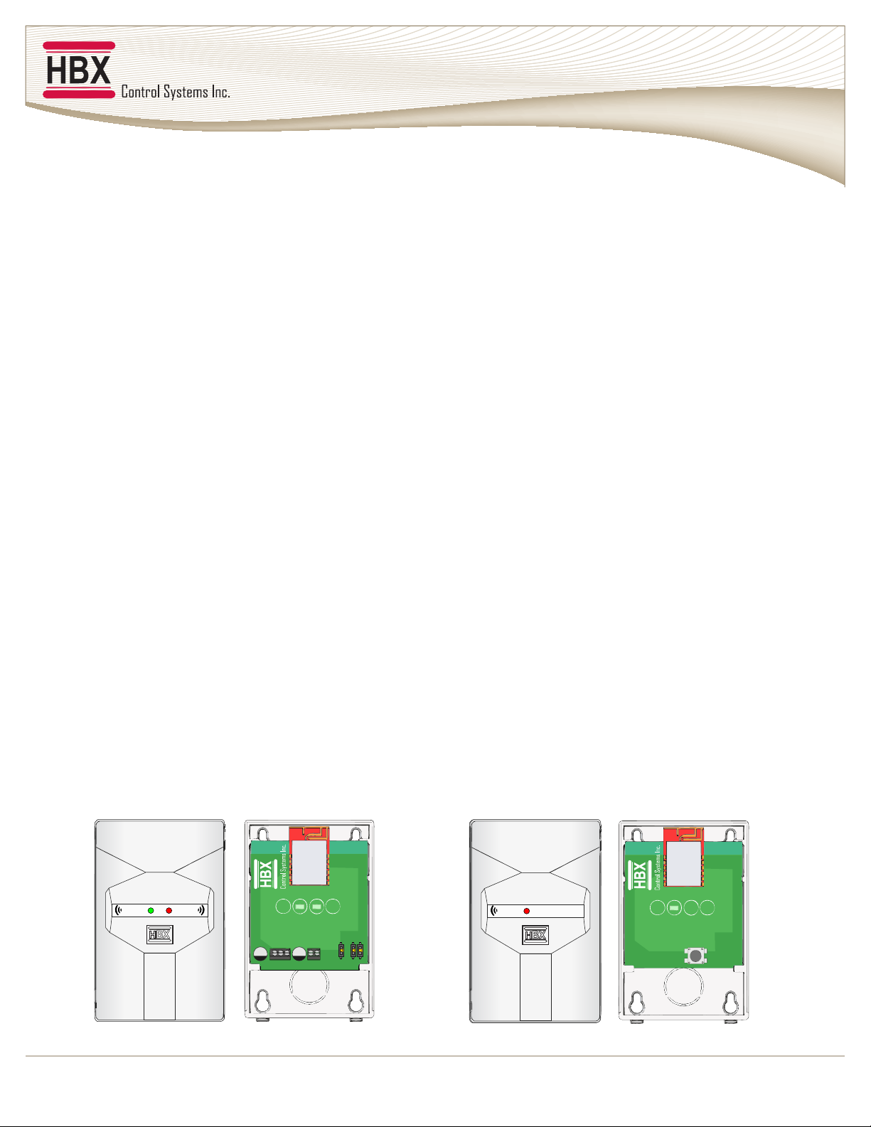
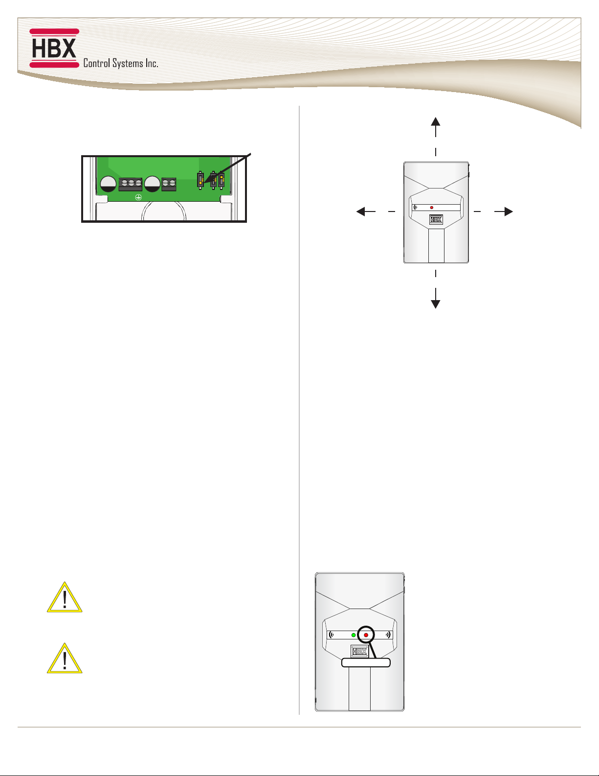
After unpacking the unit make sure the box contains:
• 1 x Base Unit
• 1 x Outdoor Unit
• 2.5mm Screwdriver
• 2 x AA Batteries (installed in Outdoor Unit)
• Instruction Manual
Make sure the part number on the unit corresponds to
the part number on the original box.
Storage
The WAV-0110 should be kept in its original shipping
carton prior to installation. In order to retain the
warranty coverage it should be stored properly:
• Store in a clean dry place
• Store within an ambient temperature range of +10ºC
to +40ºC
• If possible, store in an air-conditioned environment
where the relative humidity is less than 95%
• Do not store in places where the unit may come into
contact with corrosive gases or liquids
• Do not store in an area or upon an unstable surface
where it may become damaged due to falling

HBX WAV-0110 Outdoor Wireless Sensor
Version 1.0
Page 4
HBX WAV-0110 WIRELESS OUTDOOR SENSOR
Description
The HBX WAV-0110 Control is designed to be a microprocessor based outdoor wireless sensor system. It is easy to install,
requiring no wiring for simple installation. The weather resistant sensor is reliable and has a minimum two year battery life.
Some features of the HBX WAV-0110 are:
• Temperature range: -20ºF to 225ºF
(operating temperature range down to -40ºF)
• Proprietary pairing and communication protocol
• 500,5k,10k,20k Ohm thermistor options built in; dipswitch selectable
• Provides a 2000 ft. open air range
The HBX WAV-0110 consists of two components:
• Base Unit: This box is designed to be the interface between the controller and the outdoor unit.
• Outdoor Unit: This weather resistant box contains a thermistor sensing element to provide a reliable outdoor
temperature to the base unit.
OZOZ OZ
THERM OUT24 VAC GND
C R
Signal Power Signal Power
Signal
Base Unit WAV-0111 Outdoor Unit WAV-0112

HBX WAV-0110 Outdoor Wireless Sensor
Version 1.0
© HBX Control Systems Inc. 2015 Page 5
TECHNICAL DATA AND DIMENSIONS
Technical Data
• 1 x Power Contact: 24VAC
• 2 x Contact output
Storage:
+10ºC to 40ºC
Languages:
English
Weight:
0.177kg
RF Info:
Contains IC: 7693A-24J40MB
Contains FFC ID: 0A3MRF24J40MB
Dimensions
OZ OZ
THERM OUT24VAC GND
Signal Power
OZ OZ
THERM OUT24 VAC GND
OZ OZ
THERM OUT24 VAC GND
OZ OZ
THERM OUT24VAC GND
116 mm
78 mm
114 mm 114 mm
114 mm
76 mm 76 mm
76 mm
Front View
Outdoor Sensor - Inside View
Bottom View
Indoor Sensor - Inside View
Back View
78 mm
43 mm
OZ OZ
THERM OUT24VAC GND
Signal Power
OZ OZ
THERM OUT24 VAC GND
OZ OZ
THERM OUT24 VAC GND
OZ OZ
THERM OUT24VAC GND
116 mm
78 mm
114 mm 114 mm
114 mm
76 mm 76 mm
76 mm
Front View
Outdoor Sensor - Inside View
Bottom View
Indoor Sensor - Inside View
Back View
78 mm
43 mm
Note: Outdoor and base units are the same
dimensions.

HBX WAV-0110 Outdoor Wireless Sensor
Version 1.0
Page 6
WIRING AND INSTALLATION
Setting the Dipswitches
The Dipswitches enable you to congure the Wireless Outdoor Sensor to work with different thermistor curves. See FIG 1 to
select the appropriate thermistor curve.
FIG 1
Mounting and Wiring the Base Unit
• Place a at screwdriver into the top part of the base unit. Pry the screwdriver up on the back of the plastic and then pull off
the front cover.
• Supply 24 VAC power to the terminals in the base unit. This connection provides power to the microprocessor.
(see FIG 2A/2B)
Make sure to wire the thermistor section to the control AFTER powering the WAV-0110.
• Connect 18 AWG or similar wire to the THERM OUT terminals in the base and run the wire from here to the outdoor
sensor control terminal. See FIG 2A for regular setup, and FIG 2B for Vitodens 200 setup.
Dip 1 ON only: 500 Ohms
Dip 2 ON only: 5k Ohms
Both ON: 20k Ohms
Both OFF : 10k Ohms*
*Default Setting
ON ON
ON ON
ON ON
ON ON
Dip 1 ON only: 500 Ohms
Dip 2 ON only: 5k Ohms
Both ON: 20k Ohms
Both OFF : 10k Ohms*
*Default Setting
ON ON
ON ON
ON ON
ON ON
THERM OUT24 VAC GND
C R
THERM OUT24 VAC GND
C R
THERM OUT24 VAC GND
Vitodens 200
THERM OUT24 VAC GND
C R
Outdoor
Sensor
Input
Regular Setup
Vitodens 200 Setup ONLY
FIG 2A
FIG 2B
Ensure GND is ON
C R
THERM OUT24 VAC GND
C R
THERM OUT24 VAC GND
C R
THERM OUT24 VAC GND
Vitodens 200
THERM OUT24 VAC GND
C R
Outdoor
Sensor
Input
Regular Setup
Vitodens 200 Setup ONLY
FIG 2A
FIG 2B
Ensure GND is ON
C R
If you are using an existing
transformer to connect the Base
Unit, make sure the “C” and “R”
wires are connected to the right
terminal.
Use a seperate power supply for
the Base Unit when connecting to
a 24 VAC powered control.
Ensure Proper setup, or damage
will occur to the board.
Try not to mount the Base Unit by
high voltage wiring or equipment,
especially contactors or high
voltage switching devices.

HBX WAV-0110 Outdoor Wireless Sensor
Version 1.0
© HBX Control Systems Inc. 2015 Page 7
Initial Setup and Pairing
• Once you connect 24 VAC to the base unit, the red
power LED (D2) will start to ash (after a 15 seconds
startup process). (see FIG 3)
Base Unit
FIG 3
• Remove the battery tab from the outdoor unit.
(see FIG 4)
Base Unit
FIG 4
• Hold the outdoor unit within 1 foot of the base
unit during this pairing. (see FIG 5)
Base Unit FIG 5 Outdoor Unit
OZOZ OZ
THERM OUT24 VAC GND
C R
Red LED
D2
• Push and hold the button located on the outdoor
sensor until the red LED light turns off (approx. 15
seconds), then release the button. The LED will
switch back on after a few seconds as it is initiating
the pairing process. (see FIG 6)
Outdoor Unit
FIG 6
• Once paired, the outdoor sensor will blink 3 times.
Wireless pairing is successful when you see the green
LED on the base unit ash. The green LED should
ash up to 6 times, indicating good signal strength.
You can then put the front cover on both the base
and the outdoor sensor. At this point, you will install
the outdoor sensor. (see FIG 7)
FIG 7
Red LED
D1
OZOZ OZ
THERM OUT24 VAC
C R
Green LED
Base Unit
Red LED
Outdoor Unit
OZOZ OZ
THERM OUT24VAC
C R
Battery Tab
Max 1ft
OZOZ OZ
THERM OUT24 VAC
C R
Battery Tab
Max 1ft

HBX WAV-0110 Outdoor Wireless Sensor
Version 1.0
Page 8
Multiple Base Unit Setup
Use these settings to congure multiple base units with
one outdoor sensor.
FIG 8
Step 1: Pair the outdoor unit to one of the Base units as
per normal pairing procedure. Only power the unit that
you would like to pair with during this process.
Step 2: Make sure that the left most dipswitch on all the
base units are in the ON position(Down). This will allow
the paired base unit to talk to all other base units (FIG 8).
Step 3: Wire and power additional base units as described
on Page 6.
Mounting the Outdoor Unit
• The HBX WAV-0110 can be mounted directly onto a
wall.
• In order to prevent heat transmitted through the wall
from affecting the sensor reading, it may be necessary
to install an insulating barrier behind the enclosure.
• Mount the sensor on an exterior NORTH wall.
Choose a location protected from direct sunlight.
• Keep the sensor away from any wiring that may be
outside and also at least 1 foot away from any metal
in all directions so there is not interference with the
wireless sensor (FIG 9).
Do not mount the outdoor sensor with the
conduit knockout facing upwards as rain
could enter the enclosure and damage the
sensor.
Unit is not Water proof. Ensure that the
outdoor sensor is protected from
prolonged exposure to water.
FIG 8
FIG 9
Verify Wireless Pairing
After the base unit and the outdoor unit are installed and
the wireless pairing process is complete, verify the wireless
operation.
Steps to take for verication:
1. Press the button on the outdoor unit once. The red LED
will ash on the outdoor unit to indicate a transmit.
2. The green signal strength on the base unit should ash
up to 6 times based on the signal strength, six being the
strongest signal.
3. Wireless verication is complete
Battery Life Indicator
OZOZ OZ
THERM OUT24 VAC GND
C R
Signal Power
Check the RED power LED on
the base unit. (FIG 10) If the LED
ashes twice per second (Four
times faster than average), it
indicates that the Outdoor Unit
will require new batteries within 3
months. (FIG 11)
FIG 10
RED LED
Signal
1 ft
1 ft
1 ft 1 ft
OZOZ OZ
THERM OUT24 VAC
C R
left most
dipswitch

HBX WAV-0110 Outdoor Wireless Sensor
Version 1.0
© HBX Control Systems Inc. 2015 Page 9
Changing the Batteries
Outdoor Unit
FIG 11
Loss of Comunication Mode
The Loss of Communication mode occurs when the
base unit has lost communication with the outdoor unit
for more than 3 hours.
When the WAV-0110 is in this mode, the base unit will
output a resistance for 0°F on the control it has been
connected to.
The base unit will indicate that it is in this mode by
blinking both LED’s , ve times every three seconds
(see FIG 12).
FIG 12
Loss of Communication Troubleshooting
Step 1
Disconnect power from the base unit for 30 seconds and
reconnect it. Once the unit is powered back up it can take
up to 15 minutes for the outdoor unit to communicate with
the base unit. During this time you will still be in “Loss of
Communication” mode. If you do not wish to wait UP TO
15 minutes, you can go to the outdoor sensor and press the
button, (referred to on page 7) which will force the outdoor
unit to send a temperature to the base unit. If after trying
this step the base unit is still in “Loss of Communication”
mode, proceed to Step 2.
Step 2
Remove the cover from the outdoor unit and press the
button. The RED LED should light up when the button is
pressed. If it does not or is very dim this indicates that the
batteries are dead and need to be changed. If after trying
this step the base unit is still in “Loss of Communication”
mode, proceed to Step 3.
Step 3
Try powering down the outdoor sensor by taking out one
battery for 30 seconds. After re-inserting the battery wait
15 seconds then press the button on the unit. If after trying
this step the base unit is still in “Loss of Communication”
mode, proceed to Step 4.
Step 4
Try re-pairing the units. See page 7 for instructions.
If after trying this step the base unit is still in Loss of
Communication mode, proceed to Step 5.
Step 5
Call HBX Tech support:
Flip Forward and Out Flip and Replace Batteries
Signal Power
Telephone: +1 (403) 720 0029
Fax: +1 (403) 720 0054
suppor[email protected]

HBX WAV-0110 Outdoor Wireless Sensor
Version 1.0
Page 10
THERMISTOR OUTPUT CURVES
SUPPORTED PRODUCT EXAMPLES
-29 -20 166342
-26 -15 138482
-23 -10 11571
-21 -5 102868
-18 0 86463
-15 5 7294
-12 10 61711
-9 15 52392
-7 20 47052
-4 25 40153
-1 30 34367
2 35 29498
4 40 26686
7 45 23013
10 50 19903
13 55 17255
16 60 15000
18 65 13681
21 70 11942
24 75 10449
27 80 9164
29 85 8407
32 90 7401
35 95 653
Temp
(°C)
Temp
(°F)
Resistance
(Ohms)
-29 -20 426
-26 -15 433
-23 -10 440
-21 -5 447
-18 0 454
-15 5 461
-12 10 469
-9 15 476
-7 20 483
-4 25 490
-1 30 497
2 35 504
4 40 511
7 45 519
10 50 526
13 55 533
16 60 540
18 65 547
21 70 554
24 75 561
27 80 568
29 85 576
32 90 583
35 95 590
Temp
(°C)
Temp
(°F)
Resistance
(Ohms)
Ohms
-30 -22 88340
-20 -4 48487
-10 14 27648
0 32 16325
10 50 9952
20 68 6247
25 77 5000
30 86 4028
40 104 2662
50 122 1801
60 140 1244
70 158 876
Temp
(°C)
Temp
(°F)
Resistance
(Ohms)
-28 -19 371140
-25 -13 300459
-22 -7 244304
-18 -1 199368
-15 5 163471
-12 11 134575
-8 17 111156
-5 23 92214
-2 29 76783
2 35 64129
5 41 53777
8 47 45249
9 49 42750
13 55 36111
16 61 30615
19 67 26037
23 73 22200
26 79 18994
29 85 16297
33 91 14016
Temp
(°C)
Temp
(°F)
Resistance
(Ohms)
Dip 1 ON only: 500 Ohms
Dip 2 ON only: 5k Ohms
Both ON: 20k Ohms
Both OFF : 10k Ohms*
*Default Setting
ON ON
ON ON
ON ON
ON ON
Dip 1 ON only: 500 Ohms
Dip 2 ON only: 5k Ohms
Both ON: 20k Ohms
Both OFF : 10k Ohms*
*Default Setting
ON ON
ON ON
ON ON
ON ON
Dip 1 ON only: 500 Ohms
Dip 2 ON only: 5k Ohms
Both ON: 20k Ohms
Both OFF : 10k Ohms*
*Default Setting
ON ON
ON ON
ON ON
ON ON
Dip 1 ON only: 500 Ohms
Dip 2 ON only: 5k Ohms
Both ON: 20k Ohms
Both OFF : 10k Ohms*
*Default Setting
ON ON
ON ON
ON ON
ON ON
5K
10K
Setting Boiler Model Control Model
• Viessmann Vitodens- 100W • Heat Timer (excluding EPU-CH)
• Laars Mascot
• Laars Neotherm
• Viessmann
(excluding Vitodens-100W)
• Lochinvar
• Camus
• ATH
• Navien
• Buderus GB Series
• Allied SG, AAA &
Electric
• IBC SL, VFC
• Slant/Fin CHS
• NTI Trinity & Vmax
• Raypak
• RBI
• Smith Boiler
• Peerless Purefire
• IBC DC & HC Series
• Triangle Tube Prestige
Solo & ACVMax
• HTP Elite
• Allied HSE
• Bosch Greenstar
• Weil-McLain Ultra Series
3, Evergreen & 97+
• Slant/Fin Lynx
• Slant/Fin Jaguar
• Honeywell AQ2000
• Uponor CCN
• Taco iWorx
• HBX Controls
20K
12K
• Honeywell Building Controls

HBX WAV-0110 Outdoor Wireless Sensor
Version 1.0
© HBX Control Systems Inc. 2015 Page 11
Limited Warranty
HBX Controls warrants each of its products to be free from defects in workmanship and materials under normal use and service
for a period of 24 months from date of manufacture or 12 months from date of purchase from an HBX Authorized Dealer, if
within the above documented period after date of manufacture.
If the product proves to be defective within the applicable warranty period, HBX on its sole discretion will repair or replace said
product. Replacement product may be new or refurbished of equivalent or better specications, relative to the defective product.
Replacement product need not be of identical design or model. Any repair or replacement product pursuant to this warranty
shall be warranted for not less than 90 days from date of such repair, irrespective of any earlier expiration of original warranty
period. When HBX provides replacement, the defective product becomes the property of HBX Controls.
Warranty Service, within the applicable warranty period, may be obtained by contacting your nearest HBX Controls ofce via the
original Authorized Agent and requesting a Return Material Authorization Number (RMA #). Proof of purchase in the form a
dated invoice/receipt must be provided to expedite the issuance of a Factory RMA.
After an RMA number has been issued, the defective product must be packaged securely in the original or other suitable shipping
package to ensure that it will not be damaged in transit. The RMA number must be visible on the outside of the package and
a copy included inside the package. The package must be mailed or otherwise shipped back to HBX with all costs of mailing/
shipping/insurance prepaid by the warranty claimant.
Any package/s returned to HBX without an approved and visible RMA number will be rejected and shipped back to purchaser
at purchaser’s expense. HBX reserves the right, if deemed necessary, to charge a reasonable levy for costs incurred, additional to
mailing or shipping costs.
Limitation of Warranties.
If the HBX product does not operate as warranted above the purchasers sole remedy shall be, at HBX’s option, repair or
replacement. The foregoing warranties and remedies are exclusive and in lieu of all other warranties, expressed or implied, either
in fact or by operation of law, statutory or otherwise, including warranties of merchantability and tness for a particular purpose/
application. HBX neither assumes nor authorizes any other person to assume for it any other liability in connection with the sale,
installation maintenance or use of HBX Controls products.
HBX shall not be liable under this warranty; if its testing and examination discloses that the alleged defect in the product does not
exist or was caused by the purchasers or third persons misuse, neglect, improper installation or testing, unauthorized attempts to
repair or any other cause beyond the range of intended use, or by accident, re, lightning or other hazard.
Limitation of Liability.
In no event will HBX be liable for any damages, including loss of data, loss of prots, costs of cover or other incidental,
consequential or indirect damages arising out of the installation, maintenance, commissioning, performance, failure or
interruption of an HBX product, however caused and on any theory of liability. This limitation will apply even if HBX has been
advised of the possibility of such damage.
Local Law.
This limited warranty statement gives the purchaser specic legal rights. The purchaser may also have other rights which vary
from state to state in the United States, from Province to Province in Canada and from Country to Country elsewhere in the
world.
To the extent this Limited Warranty Statement is inconsistent with local law, this statement shall be deemed modied to be
consistent with such local law. Under such local law, certain disclaimers and limitations of this statement may not apply to the
purchaser. For example, some states in the United States, as well as some governments outside the United States (including
Canadian Provinces), may: Preclude the disclaimers and limitations in this statement from limiting the statutory rights of a
consumer (e.g. United Kingdom); Otherwise restrict the ability of a manufacturer to enforce such disclaimers or limitations; or
Grant the purchaser additional warranty rights which the manufacturer cannot disclaim, or not allow limitations on the duration
of implied warranties.

Page 12
©HBX Control Systems Inc. 2015
Phone: +1 (403) 720-0029 Fax: +1 (403) 720-0054
Email: info@hbxcontrols.com Web: www.hbxcontrols.com
HBX Control Systems Inc.
4516 - 112th Avenue SE
Calgary, AB Canada T2C 2K2
This manual suits for next models
2
Table of contents
Other HBX Accessories manuals
Popular Accessories manuals by other brands

Quincy lab
Quincy lab 140 Series operating manual

Beurer
Beurer HD 75 Cosy Taupe Instructions for use

Airmar
Airmar WeatherStation 110WXS Owner's guide and installation manual

Endress+Hauser
Endress+Hauser Oxymax COS22D operating instructions

Poweradd
Poweradd Pilot 4GS Pro user manual

EM Motorsport
EM Motorsport ADR4 installation manual