HCL PT-CB-02 Instruction Manual

Hose Clamp Electro-
Pneumatic Control Unit
Operation, Parts & Safety Manual
Original Instructions


www.hclfasteners.com
Tooling
Index
Operation
1.1 Warning & Safety Instructions
1.2 Pneumatic Tool Conrol Unit
Touch Screen
2.1 Administrator
2.2 User
2.3 Set Up
2.4 Run, Warning and Advice
Reference
3.1 Control Unit Schematic
3.2 Control Unit Wiring Diagram
3.3 Control Unit Pneumatic Diagram
CE Marking
4.1 EC Declaration of Conformity
The control unit is designed to be used with the following pneumatic tools:
Piston Tool
Calliper Tool
Calliper Tool Dry Cycle
Ezyclik Calliper Tool
Ezyclik Caliper Tool Dry Cycle

www.hclfasteners.com
Read these instructions carefully:
ELECTRICAL
An Electrical supply represents a source of considerable potential energy. Precautions should be taken to prevent accidents.
– Electrical supplies must be disconnected before any adjustments, maintenance or dismantling.
– The Maximum allowable electrical supply should be observed.
COMPRESSED AIR
A compressed air supply represents a source of considerable potential energy. Precautions should be taken to prevent
accidents.
– Maximum operating pressure – 9.9 Bar
– Recommendedairowintounit–>50L/min.
Note.Iftheairowisnotachievablealongertimedelaymayneedtobesettoallowthejawsorpistontoclosefully.
– Usea50micronlterorbetter.
– Input air must be non-lubricated.
– Compressed air should never impinge in the body.
– Ports and pipes etc. should never be blocked by hand.
– Beforeconnectinganypneumaticequipmenttoacompressedairsupply,mountings,ttings,pipeworkandelectrical
connections should be checked for security, and all or any protective transit plugs removed.
– Nopipeworkalterationsorremovalofttingsshouldbeattemptedwithairsuppliesconnected
– Compressed air supplies must be disconnected before any adjustments, maintenance or dismantling.
– The maximum allowable operating pressures should be observed.
TRAINING
The control unit must not be used by persons not properly trained in its use. Be certain that you receive proper training from
youremployer.IfyouhaveanyquestionscontactyourHCLrepresentative.
WEIGHT
Control Unit – 6.7Kg
NOISE
– Soundpressurelevelislessthan70dB
– Vibrationlevelislessthan2.5ms-2
Operation - Warning & Safety Instructions
1.1
www.hclfasteners.com
Introduction
Developed exclusively for the range of Herbie Clip
and Ezyclik pneumatic tools, the Pneumatic Control
system gives a greater level of air pressure control.
Features
In the drive to eliminate error from production lines the
control system has a number of features including:
HMI touch screen control
Digital control of air pressure – to maintain a
consistent tightening force
Digital control of clamping time – to maintain a
consistent tightening time
Dry cycle detection (tool option) – Detects tool use
without a clip being in place
In process advisory information screens
Batch and unit count control
Supervisory control
Adjustable orientation of the HMI screen
External Signal Output
A 24v output signal can be supplied to the production
line once the prescribed number of clamps has been
tightened.
Low Maintenance
TheControlUnithasnospecicmaintenance
scheduleandHCLFastenersprovidefullbackupand
servicing support.
1 or 2-Preset Program Options
The Control Unit program allows the user to save the
following process parameters within the Set Up pages:
– Clamp Time
– Tool Pressure
– Clamp Count (number of clamps per production
assembly)
– Batch Count (number of production assemblies in
batch)
If required, the Control Unit can also be set up with the
ability to save 2 different sets of
process parameters.
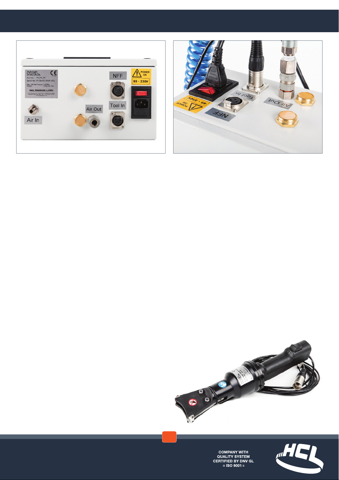
Operation - Pneumatic Tool Control Unit
1.2

www.hclfasteners.com
Start Up
Connect the Control Box to electrical and
compressed air supplies. Connect the tool to the
Control box. In both cases refer to the images
shown in the ‘Pneumatic Tool Control unit’ section
of this manual
Switch on the power to the control box
The ‘Start Up’ screen is displayed
This will switch to the Main screen automatically
after a short time but can be switched manually by
touching the screen during this period
Language
TheLanguagerequiredcanbechosenbyselecting
theagonthestartscreen
Select the required language
Select ‘Back’ to return to the Start screen
➜
➜
➜ ➜
AdministratorLogin
IntheStartscreenselect‘Login’
The‘UserLogin’Screenisdisplayed
The control box is supplied with a default
Administrator level login
Fromthe‘User’dropdownmenuselect‘Admin’
Enter default password 1234
Select‘Login’
Note.Forsecurityreasonsitisadvisedthatthe
default User ‘Admin’ is deleted once administrative
users have been set up on the control box
‘Command succcessful’ message is displayed
withinthe‘UserLogin’screen
If incorrect login details entered ‘Command
Unsuccessful’ message is displayed
➜ ➜
Touch Screen - Administrator
2.1
www.hclfasteners.com
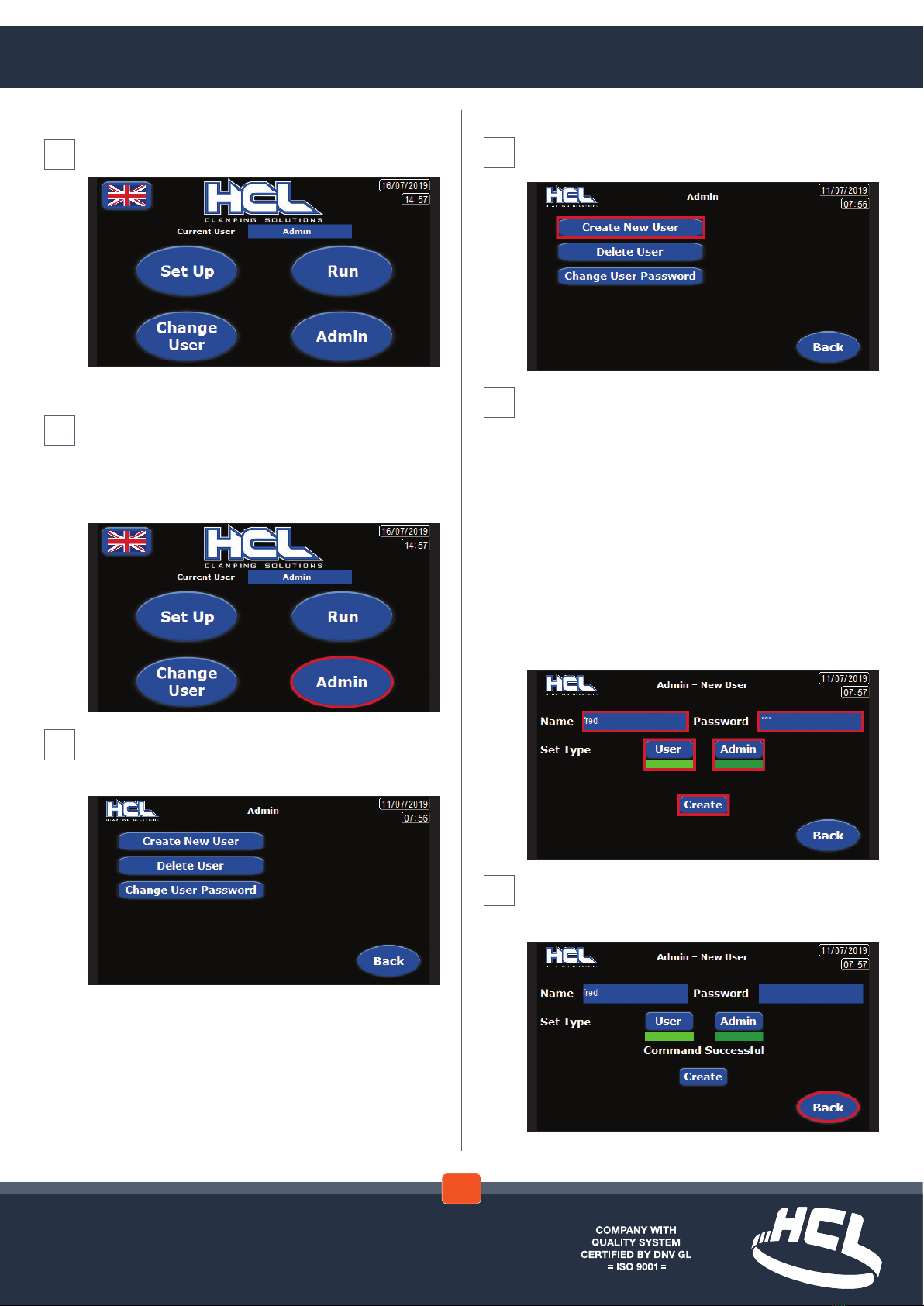
Create New User
In the ‘Admin’ screen select ‘Create New User’
– OR – ‘Back’ To return to the previous screen
In the ‘Admin – New User’ screen enter the name of
thenewuserinthe‘Name’eld
Enter the new users password in the ‘Password’
eld
Decide if the new user is a ‘User’ or if they also have
‘Admin’ authority
Selecteitherthe‘User’or‘Admin’elds
Note. When selecting ‘Admin’ both the ‘Admin’ and
‘User’eldsarehighlighted
Whenselecting‘User’onlythe‘User’eldis
highlighted
Select ‘Create’ – OR – Back’ To return to the
previous screen
In the ‘Admin’ screen the ‘Command Successful’
message is displayed
Select ‘Back’ To return to the previous screen
➜ ➜
➜ ➜
➜
AdministratorLogin(cont)
Start screen opens with the addition of an ‘Admin’
button
Administrator Actions
LoginasanAdministratorviathefrontscreen.See
AdministratorLoginsection
When logged in as an Administrator the front screen
has the option of the ‘ADMIN’ button.
Select ‘Admin’
The ‘Admin’ screen is displayed
To return to the previous page select the ‘Back’
button
➜
Touch Screen - Administrator
2.1

www.hclfasteners.com
In the ‘Admin’ screen the ‘Command Successful’
message is displayed
Select ‘Back’ To return to the previous screen
Change User Password
In the ‘Admin’ screen select ‘Change User Password’
– OR – ‘Back’ To return to the previous screen
In the ‘Admin – Change User Password’ screen
enter the name of the user in the ‘Name’ drop down
menu
Enter the users new password in the ‘Password’
eld
Entertheusersnewpasswordinthe‘Conrm
Password’eld
➜ ➜ ➜
Delete User
In the ‘Admin’ screen select ‘Delete User’
To return to the previous page select the ‘Back’
button
In the ‘Admin – Delete User’ screen select the name
of the user to be deleted in the ‘Name’ drop down
menu
Select ‘Delete’ – OR – ‘Back’ To return to the
previous screen
Inthe‘Admin–DeleteUser’screenaconrmation
message is displayed
Select ‘OK or Cancel’ – OR – ‘Back’ To return to the
previous screen
➜ ➜ ➜
Touch Screen - Administrator
2.1

www.hclfasteners.com
UserLogin–EquipmentSwitchOn
Inthe‘Start’screenSelect‘Login’
The‘UserLogin’screenisdisplayed
Select the user form the ‘User’ drop down menu
Enter the associated password
Select‘Login’
‘Command Successful’ advice message displayed
on screen
If incorrect login details entered ‘Command
Unsuccessful’ message displayed on screen –
Select ‘Close’
Depending on the type of user logged in the Start
screen opens with either:
‘Change User’ and ‘Change Password’ or ‘Change
User’ and ‘Admin’ options
➜ ➜ ➜ ➜
Change User Password (cont)
Change Password box is displayed
Select ‘Change Password’ – OR – Back’ To return to
the previous screen
In the ‘Admin – Change Password’ screen a
conrmationmessageisdisplayed
‘PleaseConrmOperation’
Select ‘OK or Cancel’
In the ‘Admin – Change Password’ screen the
‘Command Successful’ message is displayed
Select ‘Back’ To return to the previous screen
➜ ➜ ➜
Touch Screen - User
2.2

www.hclfasteners.com
UserLogin–EquipmentSwitch
On (cont)
Change User
In Start screen Select ‘Change User’
The‘UserLogin’screenisdisplayed
SelectLogout
Select the user from the ‘User’ drop down menu
Enter the associated password
Select‘Login’
➜➜ ➜
‘Command Successful’ advice message displayed
on screen
If incorrect login details entered ‘Command
Unsuccessful’ message displayed on screen
The start screen is displayed after a short time
delay
Change Password
Select ‘Change Password’
➜ ➜ ➜
Touch Screen - User
2.2

www.hclfasteners.com
Inthe‘UserLogin’screenSelect‘Logout’
Inthe‘UserLogin’screenthe‘Command
Successful’ message is displayed
Select ‘Close’
The front screen is displayed
Set Up
In Start screen Select ‘Set Up’
➜ ➜ ➜ ➜
Change Password (cont)
The ‘Current User – Password Change’ screen is
displayed
Enter ‘Current Password’
Enter ‘New Password’
Enter‘ConrmPassword’
The‘ChangePassword’eldisdisplayed
Note.Ifthe‘ChangePassword’eldisnotdisplayed
there is an error with the information entered in the
passwordelds
Select ‘Change Password’ – OR – Select ‘Back’ to
return to the previous screen
The‘Pleaseconrmtheoperation’messageis
displayed
Select ‘OK’ or ‘Cancel’
Logout
In Start screen Select ‘Change User’
➜ ➜ ➜
Touch Screen - User / Set Up
2.3
www.hclfasteners.com
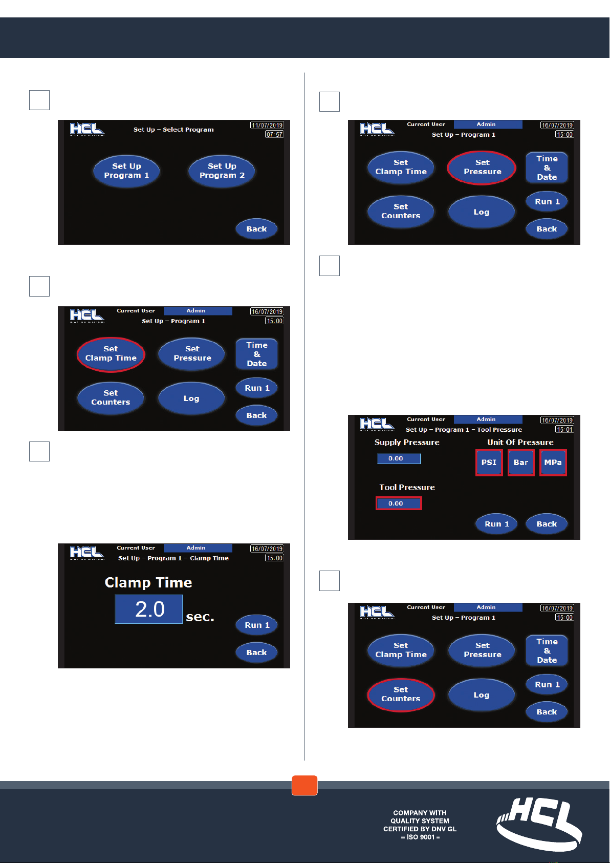
Set Up (cont)
The ‘Set Up – Select Program’ screen is displayed
Select program
Clamp Time
In the ‘Set-Up – Program #’ screen select ‘Set Clamp
Time’
The ‘Set-Up – Program # – Clamp Time’ screen is
displayed
Selectthe‘ClampTime’eld.Theon-screenkeypad
will be displayed
Enter the desired clamp time
Select ‘Run #’ to use equipment – OR – Select
‘Back’ to return to the previous screen
➜
Set Pressure
In the ‘Set-Up – Program #’ screen select ‘Set
Pressure’
The ‘Set-Up – Program # - Tool Pressure’ screen is
displayed
Select the ‘Unit Of Pressure’ type:
PSI , Bar or MPa
The‘SupplyPressure’eldisadvisoryandcannot
be set
Selectthe‘ToolPressure’eld.Theon-screen
keypad will be displayed
Enter the desired tool pressure
Select ‘Run #’ to use equipment – OR – Select
‘Back’ to return to the previous screen
Set Counters
In the ‘Set-Up – Program #’ screen select ‘Set
Counters’
➜
➜ ➜
➜ ➜
Touch Screen - Set Up
2.3
www.hclfasteners.com
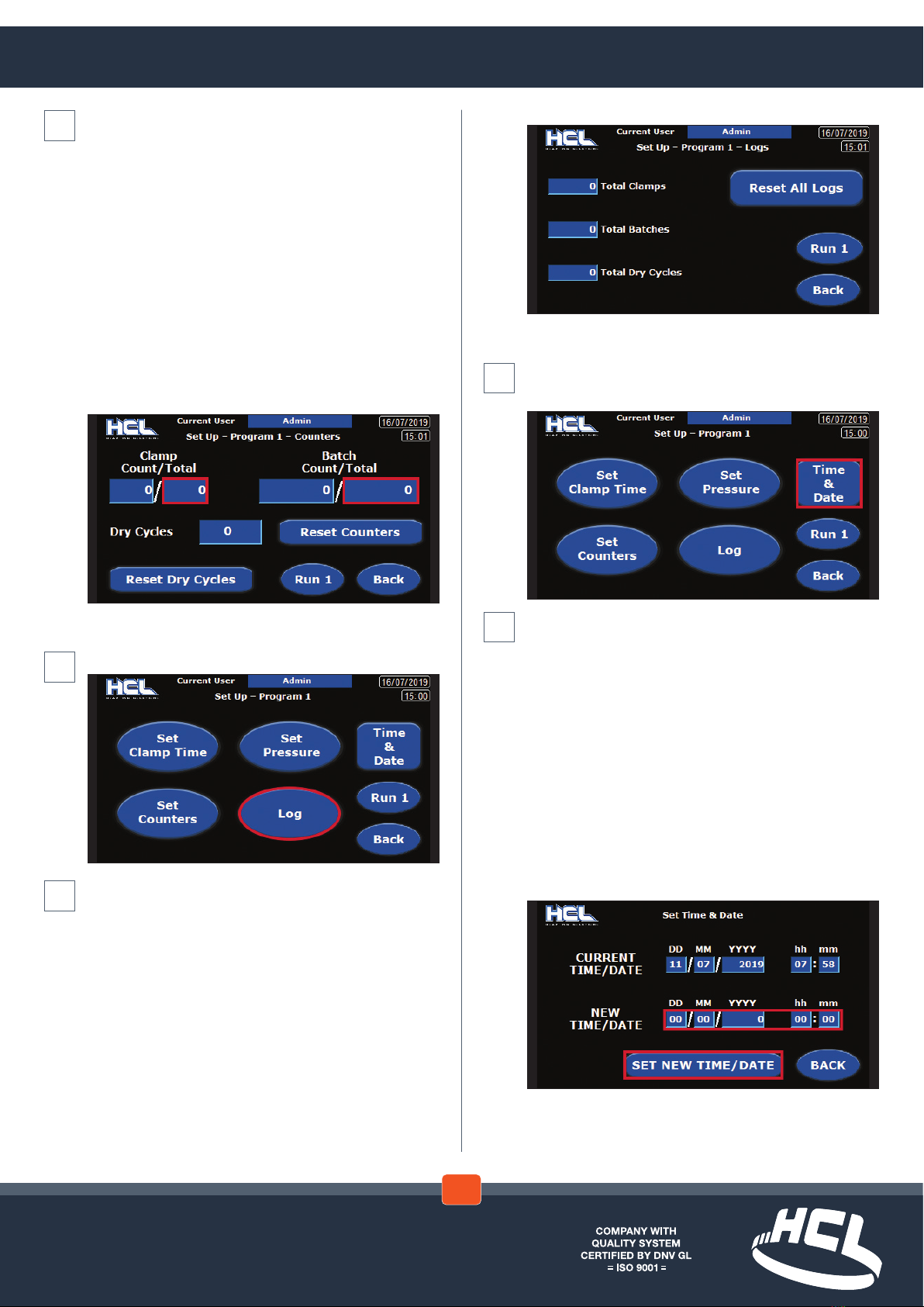
Set Time & Date
In the ‘Set-Up – Program #’ screen select ‘Time &
Date’
In the ‘Set Time & Date’ screen
The‘CurrentTime/Date’–‘DD’/‘MM’/‘YYYY’and
‘hh’:‘mm’eldsareadvisoryandcannotbeset
Inthe‘NewTime/Date’theeldsfor‘DD’/‘MM’/
‘YYYY’and‘hh’:‘mm’canbeindividuallyselected.
Foreachselectiontheon-screenkeypadwillbe
displayed
Enterthedesiredgurefor‘DD’/‘MM’/‘YYYY’and
‘hh’ : ‘mm’
Select‘SetNewTime/Date’
The newly entered selections will become the
‘CurrentTime/Date’
Select ‘Back’ to return to the previous screen
➜ ➜
The ‘Set-Up – Program # - Counters’ screen is
displayed
Note.The‘ClampCount’and‘BatchCount’eldsare
advisory only and cannot be set
Selectthe‘ClampCountTotal’eld.Theon-screen
keypad will be displayed
Enter the desired ‘Clamp Count Total’ per batch
Repeatforthe‘BatchCountTotal’eld
The counters can be zeroed by selecting ‘Reset
Counters’
The‘DryCycles’eldisadvisoryandcannotbeset
but can be zeroed by selecting ‘Reset Dry Cycle’
Select ‘Run #’ to use equipment – OR – Select
‘Back’ to return to the previous screen
SetLogs
Inthe‘Set-Up–Program#’pageselect‘Log’
Inthe‘Set-Up–Program#–Logs’screen
The ‘Total Clamps’, ‘Total Batches’ and ‘Total Dry
Cycles’eldsareadvisoryandcannotbeset.They
canbezeroedbyselecting‘ResetAllLogs’
Select ‘Run #’ to use equipment – OR – Select
‘Back’ to return to the previous screen
➜ ➜ ➜
Touch Screen - Set Up
2.3
www.hclfasteners.com
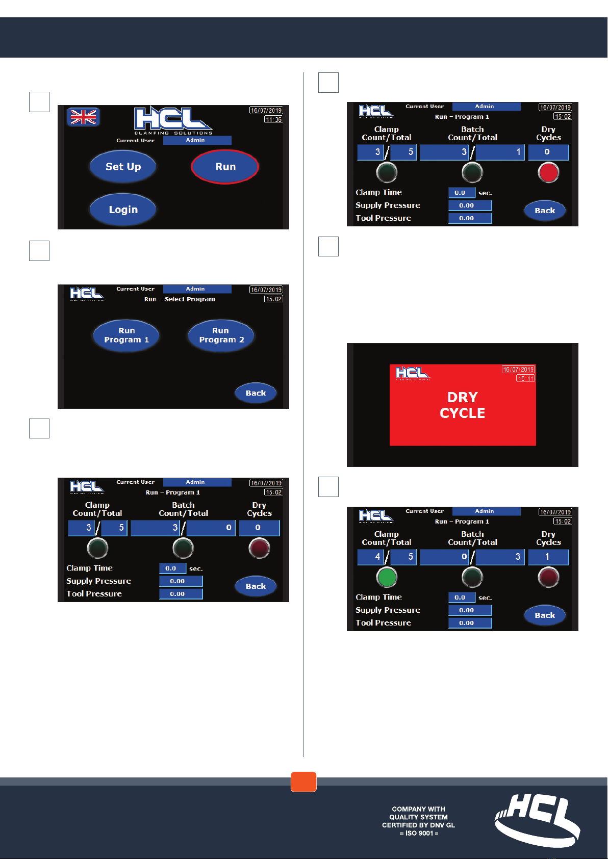
If a ‘Dry Cycle is registered the indicator light
illuminates red
To accompany the red indicator light on the ‘Run –
Program #’ screen an on screen message box ‘Dry
Cycle’ is displayed
This Indicates that the tool has been operated but
hasnotttedaHoseClampunit
Message disappears on screen after completion of
the operation cycle
On completion of a good clamp cycle the ‘Clamp
Count/Totalindicatorlightwillbeilluminatedgreen
➜ ➜ ➜
Run
In the ‘Start’ screen select ‘Run
The ‘Run – Select Program’ screen is displayed
Select the program number required –OR – Select
‘Back’ to return to the previous screen
The ‘Run – Program #’ page is displayed
The‘ClampCount/Total’,‘BatchCount/Total’,‘Dry
Cycles’, ‘Clamp Time’, ‘Supply Pressure’ and ‘Tool
Pressure’eldsareadvisoryandcannotbeset
➜ ➜ ➜
Touch Screen - Run, Warning and Advice Screens
2.4
www.hclfasteners.com
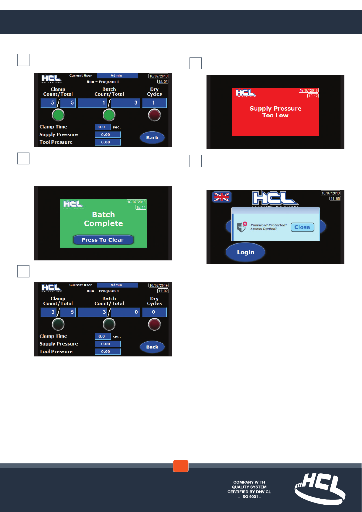
Warning and Advice Screens
‘SupplyPressureTooLow’warning
Check supply pressure and adjust
Should a user try to access the ‘Set Up’ screens
without being logged in a warning message is
displayed ‘Password Protected – Access Denied’
Select‘Close’toreturntotheFrontscreen
➜ ➜
Run (cont)
Oncompletionofthe‘BatchTotal’the‘BatchCount/
Total indicator light will also be illuminated green
To accompany the ‘Batch Total’ green indicator light
an on screen message box ‘Batch Complete’ is
displayed
Select ‘Press To Clear’ to return to the previous page
The ‘Run - Program#’ screen is displayed with the
count totals reverting to zero
➜ ➜ ➜
Touch Screen - Run, Warning and Advice Screens
2.4

www.hclfasteners.com
Reference - Control Unit Schematic
SUPPLY
NFF
V1EX
SUPPLY
R1 EX
240vAC
AIR
AIR TO
TOOL
TOOL
159
250
300
Note. The orientation of the HMI unit is adjustable
by 90, 180 and 270 degrees. This is to allow the
control unit to be located in the most suitable
position for the operator and also for access to
services.
This feature requires the removal of the control
unit front cover to enable the HMI unit to be
repositioned.
Ensure that the Control Unit is turned off before
gaining access. Refer to the Warning & Safety
Instructions within this manual.
3.1

www.hclfasteners.com
A 2
A 1
F 1 - 5 A
NL
-V+ V
P S U
3 5 W 2 4 V dc
- F 2
1 A (T )
0 - 5 Vdc
PSE5 4 0 - R 0 6
BLU
BLK
B R N
C O M3
0 V
G N D
24V
W ein te k MT 8 0 5 0 iE
0 V
0 V
AO 1 -V
AO 0 -V
O u t p u t
A n a lo g u e
T MC 2 A Q2 V
- F 3
0 . 5 A(T )
IT V 1 0 5 0 -3 1 2 C N 4
(0 .0 0 6 - 0 .9 9 M Pa )
0 - 1 0 V d c
B R N
BLU
W H I
BLK
1 4A 2
A 1 1 3 +
I0
Q 0 Q 1 V-Q 3 Q 5 V +Q 40 V
0 V
I1 I8
A I0
PE
0 V
I5
Q 6Q 2
I2 I4
24V
S E R I A L
I6
A I1
C O M I3 I7
S chneid er M2 2 1 - T M2 2 1 C 1 6 T
1 4A 2
A 1 1 3 +
85-230VAC
3
1 2
1 - 4 Tr ig g e r
0 V
4
1
2 - 3 D ry C y c l e
+ 2 4 V
3
S KT 1
S KT 2
2 3
2 0
801
2
1
8 0 0
2 2
_
0
2 1
802
803
3
Reference - Control Unit Wiring Diagram
3.2

www.hclfasteners.com
V
E X H
S U P
P R
A
Too l
S u p ply
6 m m O D
6 m m O D
6 m m O D
6 m m O D 6 m m O D
Reference - Control Unit Pneumatic Diagram
3.3

www.hclfasteners.com
Name of manufacturer: HCLFastenersLtd
Address of manufacturer: FirstAvenue,WesteldIndustrialEstate,Radstock,Bath,BA34BS,UK
Telephone: +44(0)1761417714
Email: [email protected]
WeherebydeclarethatthefollowingmachineryisinconformitywiththeMachineryDirective2006/42/EC:
Machinery description: Control Unit
Part No: PT-CB-02
Serial No: PT-CB-02- -
Applied Harmonised Standards:
Ref. No. Title
BS EN 12100:2010 Safety of machinery. General principles for design.
Risk assessment and risk reduction
BS EN ISO 4414:2010 Pneumaticuidpower.Generalrulesandsafetyrequirements
for systems and their components
InAccordancewithBSENISO/IEC17050-1:2010
BSENISO4414:2010 Pneumaticuidpower.Generalrulesrelatingtosystems
BSEN60204-1:2018 SafetyofMachinery.Electricalequipment&machines
BSEN50565-1:2014 Useforcableswithratedvoltagenotexceeding450/750V
I hereby declare that the equipment named above has been designed to comply with the relevant sections
oftheabovereferencedspecicationsandisinaccordancewiththerequirementsoftheDirective.
Name: David Coles
Position: Managing Director
Address: FirstAvenue,WesteldIndustrialEstate,Radstock,Bath,BA34BS,UK
Date: 1stJuly2018
The technical documentation for the machinery is available from the above address.
Year of
manufacture
Consecutive
number
Document reference
No. CE-1000
CE Marking - EC Declaration of Conformity
EC Declaration of Conformity
In accordance with EN ISO 17050-1-2004
4.1

Considerable effort has been made to ensure that this product conforms to our high quality standards. However, should you
experience any diculties, please contact your Sales representative providing samples and the serial code specied on the tool.
HCL – UK & Rest of the World
Tel:+44(0)1761417714
Fax:+44(0)1761417710
HCL – North America
Tel:281-717-1145
Fax:281-717-1146
Email: [email protected]
Visit www.hclfasteners.com to view our complete range of products.
November2020
©HCLFasteners.AllRightsReserved.
Your attention is drawn to the following:
HCLwarrantsthatanewHCLbandingtoolwilloperateperfunctionalspecicationsforaperiodofsixty(60)days
after the date of shipment to the owners place of business. Normal wearing parts, as outlined in the Operations,
Parts&Safetymanual,arealsocoveredbyasixty(60)daywarrantyunless,inHCL’sjudgement,thesepartshave
beensubjectedtoabnormalorextremeusage.HCL’ssoleliabilityhereunderwillbetorepairorreplace,without
charge,F.O.B.HCL,BathUK,anytoolwhichprovestonotoperateperfunctionalspecicationswithinthestated
period.HCLreservestherighttoreplaceanytoolwhichprovesnottooperateperfunctionalspecications
withaneworlike-newtoolofthesamemodel,ifinHCL’sjudgementsuchreplacementisappropriate.Anynew
replacementorlikenewreplacementtoolprovidedtoanownerwillcarryafullsixty(60)daywarranty.Anywarranty
repairedtoolwillcarryawarrantyforthebalanceoftimeremainingontheinitialsixty(60)daywarranty.This
warrantywillbeextendedtocompensateforthetimethetoolisinHCL’spossessionforwarrantyrepairs.
This warranty is void as to any tool which has been:
a)usedonnon-genuineHCLhoseclamps
b)subjectedtomis-use,misapplication,accidentdamage,orrepairedwithotherthangenuineHCLreplacement
parts.
c) improperly maintained, or adjusted, or damaged in transit or handling.
d)usedwithimproperlyltered,regulated,unlubricatedair.
e)inHCL’sopinion,alteredinawaythataffectsordetractsfromtheperformanceofthetool.
HCLMAKESNOWARRANTY,EXPRESSEDORIMPLIED,RELATINGTOMERCHANTABILITY,FITNESSOR
OTHERWISEEXCEPTASSTATEDABOVEANDHCL’SLIABILITYASASSUMEDABOVEISINLIEUOFALLOTHERS
ARISINGOUTOFORINCONNECTIONWITHTHEUSEANDPERFORMANCEOFTHETOOL.ITISEXPRESSLY
UNDERSTOODTHATHCLSHALLINNOEVENTBELIABLEFORANYINDIRECTORCONSEQUENTIALDAMAGES
INCLUDING,BUTNOTLIMITEDTO,DAMAGESWHICHMAYARISEFROMLOSSOFANTICIPATEDPROFITSOR
PRODUCTION,SPOILAGEOFMATERIALS,INCREASEDCOSTSOFOPERATIONOROTHERWISE.
Table of contents


