HD Flow3 HD-W300T User manual

ver 1.0
User Manual and Installation Guide
HD-W300T
www.hdflow.co.kr
READY
®
Wireless Full HD Sender Transmitter

2
Safety Precautions
Introduction
Product Specifications
Installation And Operation
Compliance Statements
Warranty
Read Before Operating Equipment
Unit Care Recommendations
Features
Package Contents
Video Format Supported
Audio Format Supported
Wireless Connection
Transmitter Front
Transmitter Back
Receiver Front
Receiver Back
Remote Control
Remote Control Battery Installation And Replacement
Connecting Source Components To The Transmitter
IR Flasher Installation (Setting Up IR Remote Control Capabilities for Source Devices)
IR Extender Installation (Optional)
Connecting The Receiver To The Display Device
Powering-Up HD FLOW3 Wireless AV Multi Display System
Input And Output Selection
Multicast Mode - Pairing Additional Receiver(s) With The Transmitter
Peer-To-Peer LAN (Wired) Mode Installation
Tips
Indicator Lights Decoded
Factory Reset
How To Check The Firmware Version
Supported Video Formats
FCC Compliance
CE Compliance
IC Compliance
.........................................................................................................................................3
...................................................................................................................................................3
...................................................................................................................................................................................4
...................................................................................................................................................................4
........................................................................................................................................................ 5
........................................................................................................................................................ 5
.............................................................................................................................................................. 5
.....................................................................................................................................................................6
......................................................................................................................................................................7
.........................................................................................................................................................................8
.........................................................................................................................................................................9
......................................................................................................................................................................10
........................................................................................................ 10
..........................................................................................................11
......................................................12
........................................................................................................................................12
.................................................................................................................13
...............................................................................................13
....................................................................................................................................................13
..................................................................................14
........................................................................................................................14
........................................................................................................................................................................................15
.......................................................................................................................................................15
........................................................................................................................................................................15
...................................................................................................................................15
......................................................................................................................................................16
...................................................................................................................................................................17
......................................................................................................................................................................17
.......................................................................................................................................................................17
CONTENTS
.......................................................................................................................................................................3
..................................................................................................................................................................................4
.................................................................................................................................................................5
.........................................................................................................................................................11
.............................................................................................................................................................17
......................................................................................................................................................................................18

3
SAFETY PRECAUTIONS
Read Before Operating Equipment
Thank you for purchasing our product. Before using it, please read this user manual carefully and follow the instructions
correctly for safe operation. Please keep this manual handy for future reference.
Unit Care Recommendations
• Unit can be placed vertically (preferred) or horizontally.
• To clean, use a soft, dry cloth only. Do not use water or other cleaning products as they may cause
electrical failure or damage the surface of the product.
Keep the product out of reach of
children.
Keep the product away from
external heat sources such as
heaters or stoves.
Do not insert foreign objects into
the unit.
Do not place the unit on an
unstable surface or in a poorly
ventilated area.
Make sure to plug the AC power
adaptors firmly into wall outlets.
Do not use the unit near any
flammable substances or
combustible sprays.
If any part of the AC power
adaptor looks damaged, do not
use the product immediately.
Keep the product unplugged if
unused for an extended period
of time.
If there is any unusual sound,
smoke or odor coming from the
product, immediately unplug the
product.
Keep the battery of remote control
out of reach of children.
Do not attempt to open the
outer case of the Transmitter or
Receiver. Doing so will void the
product warranty.
Keep the remote control away
from humidity and/or liquids.
4
HD FLOW3 Wireless AV Multi Display System provides Full HD 1080p signal transfer, including 3D signal*,
without the hassle of running cables. Create brilliant HD quality multimedia for signage, presentations, or entertainment
in any location, completely un-tethered to your source device!
By simply connecting the Transmitter to a multimedia device such as a computer, set-top box, or Blu-ray™ player and
connecting the Receiver to a display device, instant high definition digital audio and video can be placed into in any commercial
or residential setting. HD FLOW3 Wireless AV Multi Display System transmits through walls and floors to allow the
components to be neatly tucked away in an AV rack or media cabinet, and is the ideal solution for quick and easy installation
where running cable is cost prohibitive or simply not an option.
* Works with passive 3D signals
Features
• Low latency: ≤21ms.
• Supports both digital (HDMI) and analog (Component, Composite) video/audio.
• Supports Wireless or Wired connection - IEEE 802.11n 5 GHz WiFi, LAN connection.
• Two internal antennas (supporting MIMO).
• HDCP v1.3 compliant.
• Supports both DTV & VESA standards: DTV: 1920x1080i60/p60, 1280x720p50/60, 720x576i50/p50, 720x480i60/p60,
VESA : SXGA(1280x1024), WXGA(1280x800), XGA+(1152x864), XGA(1024x768), SVGA(800x600), VGA(640x480),
1280x960, 1360x768.
• Supports passive 3D content.
• Plug and play setup requires no software programming.
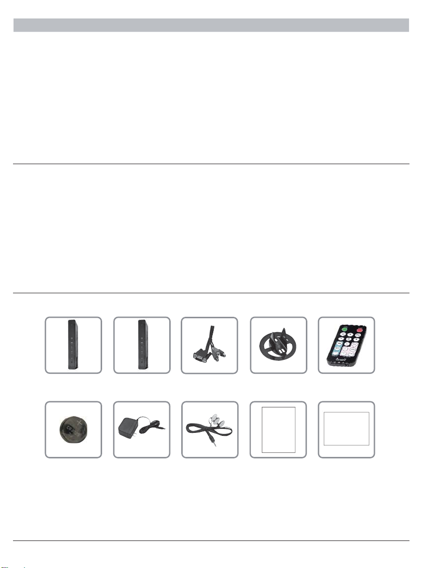
Package Contents
Ensure that the following items are present in the package.
ReceiverTransmitter
Battery IR-Flasher
Component
Adaptor
Manual
Stand (2)
Manual Quick Start Guide
Remote Control
Quick Start GuideAC Adaptor (2)
INTRODUCTION

5
HD-W300T
Video Input
(Transmitter)
3x HDMI up to 1080p60
1x HDMI pass-thru output (pass-thru port mirrors HDMI 1)
1x PC Video
1x Component & composite (via included dongle)
Video Output
(Receiver)
1x HDMI up to 1080p60
1x Component
1x Composite
Encoding
Decoding
Wireless Connection
Wire Connection
USB
Audio
Audio Input
Audio Output
Video Resolution
Video Latency
Frequency
Range
Multicast
Security
HDCP Version
Antenna Type
IR Emitter
Control Remote
Power
H.264 Baseline Profile
H.264 Baseline, Main, High Profile
IEEE 802.11n
RJ45 LAN port, 10/100/1000 Base
Type "A" both Transmitter and Receiver for firmware updates only
2 CH PCM, 48kHz, 16 Bit
3.5mm Stereo Mini Jack (Transmitter)
3.5mm Stereo Mini Jack and RCA Stereo Jack (Receiver)
480i/p, 720p, 1080i/p (24/30 fps)
21mS
5.15~5.25GHz / 5.725~5.825GHz (Limited band may be preset based on the regional regulations.)
210 ft (64M)
Up to 6 receivers (Requires additional receiver units)
WPA2 Personal and AES
1.3
MIMO, 2x Internal
3 IR Emitters on a single wire
17 button IR remote
12 VDC at 2 Amps (both transmitter and receiver)
1. Video Format Supported
2. Audio Format Supported
3. Wireless Connection
4. WiFi Channel Frequencies
• Digital Video
- HDMI : Up to 1080p @ 24Hz, 25Hz, 30Hz, 50Hz, 60Hz
• Analog Video
- Composite : 480i @ 60Hz, 576i @ 50Hz
- Component : 1080i @ 50Hz, 60Hz, 720p @ 50Hz, 60Hz, 480p @50Hz, 60Hz
- VGA : Up to 1920x1080 @ 50Hz, 60Hz
• Analog
• Digital
• Receiver outputs stereo audio
• Unicast (Peer-to-Peer) Wireless Mode
• Multicast Wireless Mode
• 5.15~5.25GHz / 5.725~5.825GHz (Limited band may be preset based on the regional regulations.)
PRODUCT SPECIFICATIONS

6
1
4
5
6
7
8
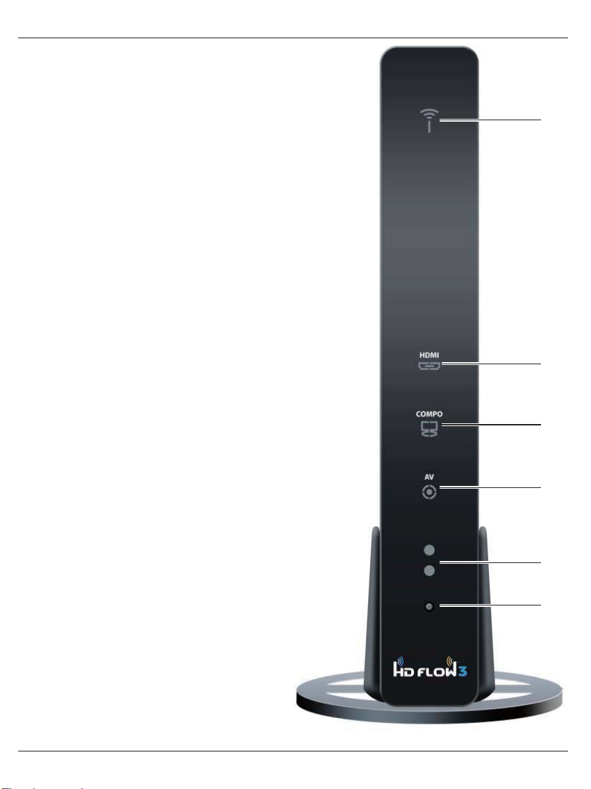
Transmitter Front
1. Power/Link Indicator Light
• Blinking indicator light - Establishing link between the
Transmitter and the Receiver.
• Solid indicator light - Link between the Transmitter
and Receiver has been established and is ready for
signal transmission.
2. HDMI 1
• The HDMI 1 indicator light will be illuminated when
the HDMI 1 port is selected for video input.
• If there is no signal, and/or the cable is not
connected, the indicator light will blink.
3. HDMI 2
• The HDMI 2 indicator light will be illuminated when
the HDMI 2 port is selected for video input.
• If there is no signal, and/or the cable is not
connected, the indicator light will blink.
4. HDMI 3
• The HDMI 3 indicator light will be illuminated when
the HDMI 3 port is selected for video input.
• If there is no signal, and/or the cable is not
connected, the indicator light will blink.
5. PC
• The PC indicator light will be illuminated when the PC
In port is selected for video input.
• If there is no signal, and/or the cable is not
connected, the indicator light will blink.
6. AV
• The AV indicator light will be illuminated when the AV
In port (Composite) is selected for the video input.
• If there is no signal, and/or the cable is not
connected, the indicator light will blink.
7. IR Window
• IR receiving window enables remote control of the
transmitter and the receivers.
8. Link/Source Selection Button
• When powered on: Press for one second to select
the video input source. Each press of the button
will cycle through the available video input "HDMI1→
HDMI2→HDMI3→PC→AV →HDMI1" in sequence.
• Press and hold for 8 seconds until all indicator lights
blink synchronously, you are now in Scan/Pairing
Mode.
3
2

7
4 3
6
7
8
9
10
2 1
5
Transmitter Back
1. HDMI 1 IN
• HDMI1 input port.
2. HDMI Pass-Thru
• Outputs a duplicate of the source that is plugged into
HDMI 1.
3. HDMI 2 IN
• HDMI2 input port.
4. HDMI 3 IN
• HDMI3 input port.
5. USB
• USB port is used for service only.
6. IR-OUT
• Connects IR Flasher to the Transmitter for remote
control of external devices which are connected to
the Transmitter (i.e. Blu-Ray player, DVD, STB, etc).
7. PC AUDIO-IN *
• Stereo audio input port for PC, component, or
composite source.
8. PC-IN (VGA)**
• Supports component and composite input with
included Component/Composite Adaptor.
9. LAN
• LAN port used for wired connection alternative.
10. DC
• 12V DC power input.
* For the audio part of a component media source, use the PC
Audio input port with a 3.5mm to RCA cable (not included).
** If using the PC Video input port for component (YPbPr) or
composite media source, use the included
Component/Composite to VGA adaptor. For composite, use
the green jack on the adaptor for the yellow video plug.
8
Receiver Front
1. Power/Link Indicator Light
• Blinking indicator light - Establishing link between the
Transmitter and the Receiver.
• Solid indicator light - Link between the Transmitter
and Receiver has been established and is ready for
signal transmission.
2. HDMI
• The HDMI indicator light will be illuminated when the
HDMI port is selected for video output.
• If there is no signal, and/or the cable is not
connected, the indicator light will blink.
3. COMPO
• The COMPO (component) indicator light will be
illuminated when component output is selected for
video output.
• If there is no signal, and/or the cable is not
connected, the indicator light will blink.
4. AV
• The AV indicator light will be illuminated when the AV
port (composite) is selected for the video output.
• If there is no signal, and/or the cable is not
connected, the indicator light will blink.
5. IR Window
• IR receiving window enables remote control of the
transmitter and/or source components.
6. Link/Output Selection Button
• When powered on: Press for 1 second to select the
video output source. Each press of the button
will cycle through the available video outputs
"HDMI→COMPO→AV →HDMI" in sequence.
• Press and hold for 8 seconds until all indicator lights
blink synchronously, you are now in Scan/Pairing
Mode.
1
2
3
4
5
6

9
1
2
3
4
5
6
7
8
Receiver Back
1. HDMI-OUT
• HDMI output port
2. AV-OUT
• Composite video output port
3. IR-IN *
• Connects IR Extender in order to extend IR reception range.
4. AUDIO-OUT **
• 3.5mm stereo audio output port for component output.
5. COMPONENT-OUT **
• Component Video output port
6. USB
• USB port used for service
7. LAN
• LAN port used for wired connection alternative
8. DC
• 12V DC Power Input
* For Better IR reception range,
use the IR input port with IR extender (not included).
** For the audio part of a component media source, use the PC
Audio Output port with a 3.5mm-to-RCA cable (not included).
10
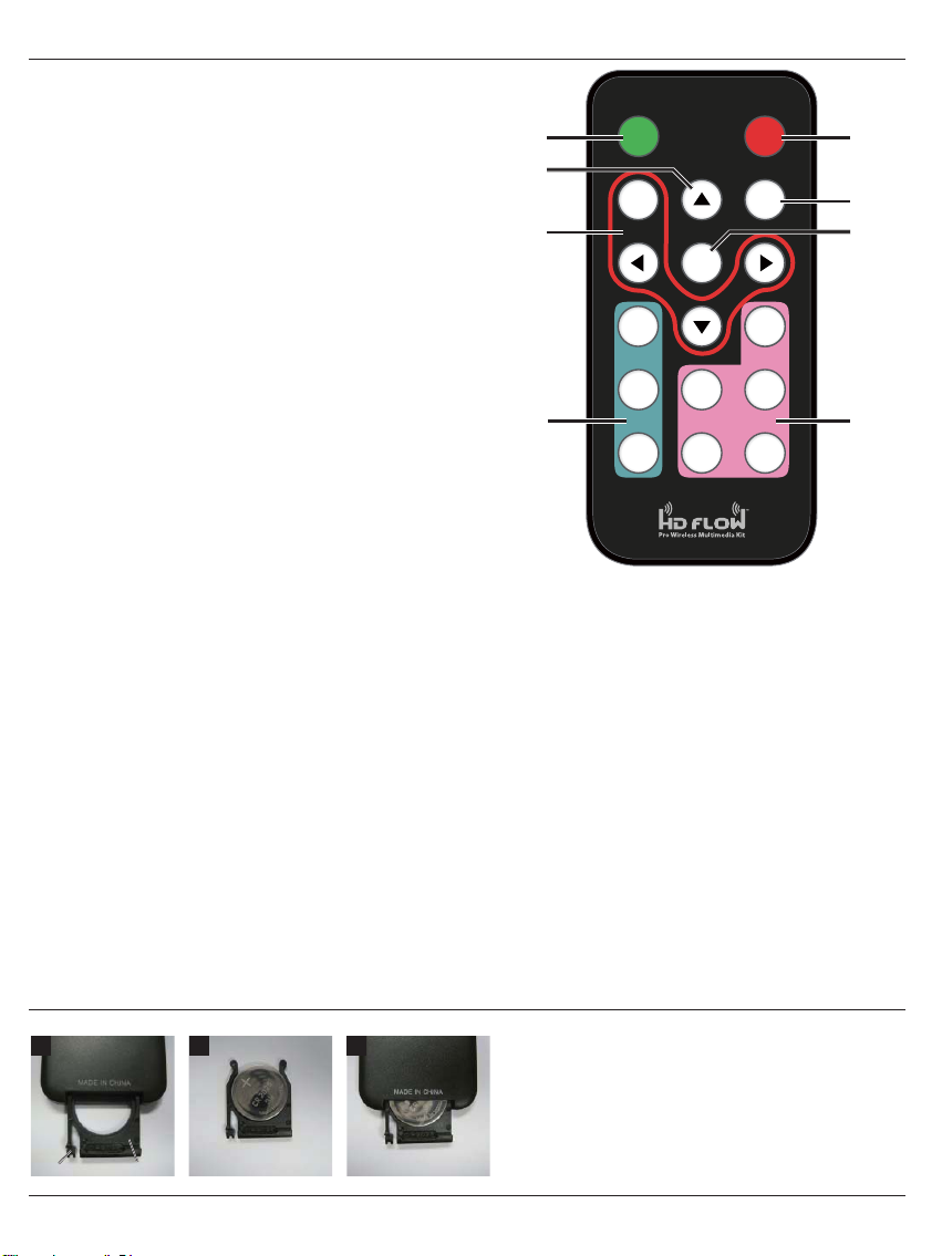
Remote Control
1. POWER ON Button
• Turns the Transmitter and Receiver power ON
2. POWER OFF Button
• Turns the Transmitter and Receiver power OFF
3. INFO/OK*
• Displays the following information on the screen:
Transmitter - WiFi IP, LAN IP, and Source
Resolution.
Note: The Transmitter unit’s information will
only be displayed if the connection between the
Transmitter unit and Receiver has been
established.
Receiver - WiFi IP, WiFi Channel, LAN, SSID,
Display Resolution, WiFi Reception Strength.
*Displayed information will disappear automatically after
30 seconds.
4. VIDEO OUT (Receiver)
• Selects the Audio/Video output port of the Receiver.
HDMI - Selects HDMI as the Audio/Video output.
Component - Selects Component as the
Audio/Video output.
AV - Selects AV as the Audio/Video output.
Note: Remote must be pointing directly at the Receiver to
control its output settings. This may also be accomplished
without the use of the remote control by toggling between
outputs via the Link/Output Selection Button on the
Receiver.
5. VIDEO IN (Transmitter) - Selects the Video input port of the Transmitter.
• HDMI1 - Selects HDMI1 as the Audio/Video input.
• HDMI2 - Selects HDMI2 as the Audio/Video input.
• HDMI3 - Selects HDMI3 as the Audio/Video input.
• PC - Selects VGA/Component as the Audio/Video input.
• AV - Selects Composite as the Audio/Video input (requires included
Component/Composite adaptor).
6. Scan
• Selects Scan/Pairing mode. System will re-scan among 10 possible WiFi frequencies and select the optimum available
channel. The channel selected will be displayed when “Info” is pressed.
7. MENU and DOWN, RIGHT, LEFT Buttons
• Disabled - for future use.
8. UP Button
• This will scroll through the possible IR frequencies. This device accommodates most IR protocols in use today. To do
so it will require selecting the one of four possible carrier frequencies available for IR control. Press the UP arrow to
scroll between 31 KHz, 38 KHz, 47 KHz and 57 KHz frequencies.
• Select a frequency and try your source remote. If the control responds, then you have selected the correct one. If the
device does not respond, try another frequency. If no frequencies seem to work, ensure the IR emitter is located in the
correct location on the source component.
POWER POWER
RECEIVER TRANSMITTER
FFONO
MENU SCAN
/ BACK
INFO
/ OK
HDMI HDMI1
COMPONENT PC HDMI2
AV AV HDMI3
1
7
4
2
6
5
3
8
Remote Control Battery Installation And Replacement
The battery clip is located on the bottom of the remote control.
Battery ClipTab
123 Push the tab, located on the left of the battery clip, to the
right and pull out the clip.
Place the battery into the clip, positive (+) end facing up
as shown.
Place the clip back into the remote to complete the
installation.
1.
2.
3.
11
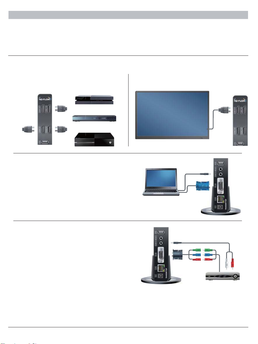
b. VGA Media Source
• Video - Connect the VGA cable from the media
source’s VGA output to the Transmitter’s VGA input.
• Audio - A 3.5mm stereo audio cable is required (not
included) to transmit audio when using this input.
Connect the 3.5mm stereo audio cable from the VGA
source component’s audio output to the Transmitter's
PC AUDIO-IN port.
c. Component Media Source
• Video – Connect the Component Video
output (YPbPr) from the source, into the
Component/Composite Adaptor (included). Connect
the Component/Composite Adaptor
to the PC-IN port on the Transmitter.
• Audio - A 3.5mm stereo audio cable is required (not
included) to transmit audio when using this input.
Connect the 3.5mm stereo audio cable from the VGA
source component’s audio output to the Transmitter's
PC AUDIO-IN port.
• Connect HDMI cable from the Transmitter’s pass-thru
output port to the input of the display device to enjoy
the video coming through HDMI1 only.
Before starting the installation, please ensure that all source components (Blu-ray player, cable box, etc.) and the display
equipment (TV, display, projector, etc.) are turned off.
For initial setup of your HD FLOW3 system complete steps A, B, C, D, E and F in order.
A) Connecting Source Components To The Transmitter
a. HDMI Media Source
•Note: It is recommended that HDMI1 input port be used if only one HDMI source component is present.
INSTALLATION AND OPERATION
• Connect HDMI cable from the source components
output to the Transmitter's HDMI1 or HDMI2 or
HDMI3 input port.

12
B) IR Flasher Installation (Setting Up IR Remote Control Capabilities for Source Devices)
IR Flashers are provided to allow for control of up to three source devices using the device’s original remote control at the
Receiver location.
1. Connect the provided IR Flasher to the IR-OUT port of the Transmitter.
2. Find the location of the IR window on your component and adhere the IR Flasher Eye directly over the IR window of your
component.
•Note: One IR Flasher Eye is to be used for one component device.
•Tips: Most often the IR window on the source device is easier to locate with direct light shining on sections of the
front panel of the device (a small flashlight or a camera phone flashlight works well).
IR-OUT Port
IR Flasher Eye
d. Composite Media Source
• Video – Connect “yellow” composite video RCA to
green port on Component/Composite Adaptor.
• Audio – A 3.5mm stereo audio cable is required (not
included) to transmit audio when using this input.
Connect the 3.5mm stereo audio cable from the VGA
source component’s audio output to the Transmitter's
PC AUDIO-IN port.
C) IR Extender Installation(Optional)
Install the IR Extender by plugging in the IR Extender (not included) into the IR-IN port on the Receiver.
(IR Extender use is optional. Use the IR Extender when the Receiver is out of sight or to extend the range of the Receiver's
IR reception range.)
13
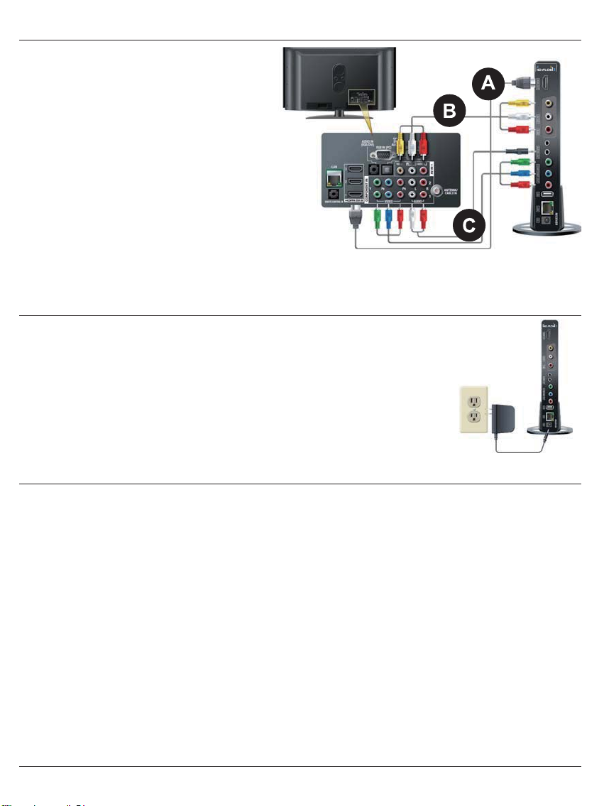
D) Connecting The Receiver To The Display Device
Note: Connect the Receiver to the display device using
the port with the highest capable resolution; HDMI port
is preferred. The HD FLOW3 is a video switch, and as
such will upconvert all inputs with resolutions of 480p,
720p, and 1080i/p through the HDMI Output.
A. HDMI Output to Display
• Connect the HDMI cable from the Receiver's
HDMI output to the display device's HDMI input.
B. Composite Output to Display
• Connect the composite RCA cable from
the Receiver's AV output to the display device's
composite input.
C. Component Output to Display
• Video - Connect the component video (YPbPr)
cable from the Receiver's COMPONENT-OUT to
the display device's component input.
• Audio - A 3.5mm-to-RCA stereo audio cable
is required (not included) to transmit audio when using this input. Connect the 3.5mm end of the cable to the Receiver's
AUDIO-OUT port, then connect the RCA side of the cable to the RCA ports on the display device.
E) Powering-up HD FLOW3 Wireless AV Multi Display System
1. Plug in the power adaptors for the Transmitter and the Receiver to available power outlets.
2. Plug in the other end of the power cables to the Transmitter and then to the Receiver. The
units will automatically turn on.
3. Turn on your display device (TV, monitor, projector, etc.).
4. While turning on the display device, the HD FLOW3 System will be going through the
start up process. The process takes approximately 45 seconds to complete. The
Power/Link Indicator Light on the Transmitter and Receiver should be flashing at first.
Flashing indicates that the units are establishing a secure connection. Wait until the
connection is successfully established, indicated by a solid Power/Link light on the
Receiver.
F) Input And Output Selection
1. Select the output used to connect the Receiver to the display. There are two ways to choose output sources on the
HD FLOW3 Receiver:
a. Using the provided remote - Press the desired output while pointing the remote at the Receiver.
b. Using the Link/Output Selection Button on the Receiver - To toggle between outputs press the Link/Output Selection
Button for one second on the unit and release.
At this time the output Indicator Light will become solid and the HD FLOW3 logo will appear on the display device if there
is no source providing content. The HD FLOW3 logo is only displayed when the receiver is working with the display, but no
content is coming from the transmitter.
2. Turn on the desired media source device that is connected to the Transmitter.
3. Select the desired media source input on the Transmitter. There are two ways to select the source input on the HD FLOW3
Transmitter:
a. Using the provided remote - Press the desired input while pointing the remote at the Transmitter.
b. Using the Link/Source Selection Button on the Transmitter - To toggle between Inputs press the Link/Source
Selection Button for one second on the unit and release.
4. Play the source device media content and enjoy up to a Full HD 1080p wireless entertainment experience.
Notes:
1. Audio and video sources will switch simultaneously whether using the remote or Selection Buttons.
2. Inputs on the Transmitter and Receiver can be switched by pointing the remote at the Transmitter or Receiver ONLY if
the connection between Transmitter and Receiver has been established, indicated by a solid link light. If the connection
between Transmitter and Receiver has not been established, the inputs need to be selected at the location of each unit
using either of the above input and output selection methods.
14
Multicast Mode - Pairing Additional Receiver(s) With The Transmitter (Optional)
Multicast Wireless Mode enables the Transmitter to stream AV media from one Transmitter to up to six Receivers.
Note: Your HD FLOW3 Wireless AV Multi-Display System comes pre paired. This section is only needed if you have
separately purchased additional Receiver(s).
If you have purchased additional Receiver(s) use the following instructions to add the Receiver(s) to the current system,
or follow the steps in the HD FLOW3 Receiver manual. The system can have receivers added at any time.
Each receiver will have to be paired with the transmitter one at a time. Do not begin pairing another receiver until the previous
receiver has rebooted after pairing as described in the steps below. A maximum of 6 receivers may be paired to one transmitter.
1. Press and hold the “Link/Source” button on the transmitter for 8 seconds. The lights will blink sequentially from top to
bottom. The transmitter will remain in pairing mode for 2 minutes or until it senses a receiver trying to link.
2. Press and hold the “Link/Output” button on the desired receiver for 8 seconds. The lights will first blink sequentially from top
to bottom; then in various patterns. After about 30 seconds the receiver will successfully link with the transmitter and then
shut off and reboot itself. The entire process will take under 1 ½ minutes and video will not appear on the display until the
process is complete. Video on the additional paired receivers will be lost during this process.
3. Repeat steps 1 and 2 for each additional receiver, if any.
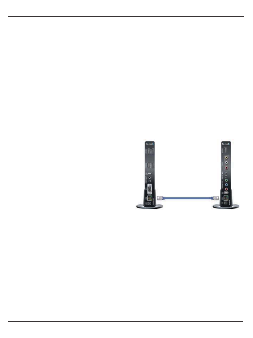
Peer-To-Peer LAN (Wired) Mode Installation
1.
2.
3.
Connect the LAN cable between the LAN ports on the
Transmitter and Receiver.
Plug both the Transmitter and Receiver into power.
When the HD FLOW3 system powers up it will detect
the wired connection upon power up and not enter
wireless mode. The boot process should be complete in
about 45 seconds. . The WiFi indicator lights on the front
of both the Transmitter and the Receiver will be solid.
Note:
To return the units back to WiFi mode, unplug power on both Transmitter and Receiver, then unplug the LAN cable, and repower
the Transmitter and Receiver. The video and audio will be lost during this process.

15
Tips
If the Transmitter and Receiver are not establishing a connection:
1. It is recommended to unplug the power to both units for 30 seconds and then plug them back in.
2. If the above tip does not assist, please reference the Factory Reset section of this manual.
If the connection has been established and the HD FLOW3 logo can be seen on the display device, but content is not playing
when initiated:
1. Ensure that source cables are properly connected.
2. Ensure the Transmitter is set to the proper input port and that the Receiver is set to the proper output port.
3. Ensure the source is operating.
4. The display device needs to be able to support the resolution of the media source that is being streamed. Utilizing the INFO
button, while connected via HDMI, will allow you to see the EDID resolution data that the display device accepts.
(Example - If the display device supports the highest resolution of 720p but the source device is outputting 1080p content,
the content needs to be downscaled to the maximum resolution of the display device, in this case 720p).
If the HD FLOW3 logo nor the video content are being displayed, verify that the output selection on the Receiver and input
selection of the display are correct. Also, make sure cables are completely pressed into place and secure, and that the selected
source content is playing.
Indicator Lights Decoded
1. Transmitter/Receiver
• Power/Link Indicator Light:
Flashing - Units are booting and establishing a secure connection for AV transfer.
Solid - Link between the Transmitter and Receiver(s) has been established and is ready for signal transmission.
• All Indicator Lights:
Lights blinking sequentially from top to bottom - Unit is in Scan Pairing Mode searching for other HD FLOW3
devices.
2. Transmitter:
• HDMI1, HDMI2, HDMI3, PC, AV - The indicator light will be lit to indicate the input that is currently selected. If the
selected input does not have a connection or the signal from the media source is not present, the selected input
indicator light will be flashing.
3. Receiver:
• HDMI, COMPO, AV - The indicator light will be lit to indicate the output that is currently selected. If no output device
is connected to the selected output port the indicator light will be flashing.
Factory Reset
CAUTION:
Factory reset will revert all settings to factory defaults. It is not recommended to perform a factory reset on multicast
systems (systems with two or more receivers) as the pairing will be forgot. One will have to re-pair the additional
receivers if a factory reset is completed.
To complete a factory reset, complete each of the steps below for both the transmitter and receiver. These do not need to be
done at the same time.
1. Unplug the device from its power source.
2. Press and hold the Link/Source (Tx) or Link/Output (Rx) Selection button on the front panel.
Plug the DC power back into the unit being reset.
3. Continue holding the Link/Source (Tx) or Link/Output (Rx) Select button for about 6 seconds until all lights blink at the same
time then release.
4. Allow the system to re-start and show content.
How To Check Firmware Version
1. Make sure the HD FLOW3 System is up and running.
2. Using the HD FLOW3 remote supplied, point it at the Receiver IR window. Press the Info/OK button. In the list of
information there will be stated “Firmware Version:”

16
O - Compatible X - Not Compatible ^ - Compatibility varies based on output device settings
Notes:
1. 1600 x 1200p60 is a reduced format.
2. HD FLOW3 simply relays the input format of the video from the Transmitter to the Receiver. HD FLOW3 does not
change the video format. If you want to change the output resolution, you should change the format on the external device
which is connected to the Transmitter.
3. When transmitting NTSC:480i or PAL:576i from the Transmitter, COMPONENT-OUT MUST be used at the Receiver.
4. Only HDMI 480i resolution input will provide composite AV-OUT signal at the Receiver. For all other resolutions, use
HDMI-OUT or COMPONENT-OUT at the Receiver.
5. PC-IN fully supports resolutions noted above ONLY when HDMI-OUT is used at the Receiver.
Supported Video Formats
Video
Standard Resolution HD FLOW Transmitter HD FLOW Receiver
HDMI D-Sub AV(CVBS) HDMI COMP AV(CVBS)
"VESA
Format
(PC standard)"
640 x 480p60 O O X O X X
640 x 480p70 O O X O X X
640 x 480p85 O O X O X X
800 x 600p60 O O X O X X
800 x 600p70 O O X O X X
800 x 600p85 O O X O X X
1024 x 768p60 O O X O ^ X
1024 x 768p70 O O X O X X
1024 x 768p85 O O X O X X
1152 x 864p60 O O X O ^ X
1152 x 864p70 O O X O X X
1152 x 864p85 O O X O X X
1280 x 800p60 O O X O X X
1280 x 960p60 O O X O ^ X
1280 x 960p70 O O X O X X
1280 x 960p85 O O X O X X
1280 x 1024p60 O O X O ^ X
1360 x 768p60 O O X O X X
1440 x 900p60 O X X O X X
1600 x 1200Rp601 O O X O ^ X
1600 x 900p60 O X X O X X
1680 x 1050p60 O O X O X X
"DTV
Format
(TV standard)"
720 x 480I60(NTSC) O O O X O O
720 x 576I50(PAL) O O O X O O
720 x 480p60 O O X O O X
720 x 576p50 O O X O O X
1280 x 720p50 O O X O O X
1280 x 720p60 O O X O O X
1920 x 1080i50 O O X O O X
1920 x 1080i60 O O X O O X
1920 x 1080p24 O O X O X X
1920 x 1080p25 O X X O X X
1920 x 1080p30 O X X O X X
1920 x 1080p50 O O X O X X
1920 x 1080p60 O O X O X X

17
FCC Compliance
This equipment has been tested and found to comply with the limits for a Class B digital device, pursuant to part 15 of the FCC
Rules. These limits are designed to provide reasonable protection against harmful interference in a residential installation.
This equipment generates, uses, and can radiate radio frequency energy and, if not installed and used in accordance with the
instruction manual, may cause harmful interference to radio communications. However there is no guarantee that interference
will not occur in a particular installation. If this equipment does cause harmful interference to radio or television reception, which
can be determined by turning the equipment off and on, the user is encouraged to try to:
1. Relocate the receiving antenna.
2. Increase the separation between equipment and Receiver.
3. Connect the equipment into an outlet on a circuit different from that to which the Receiver is connected.
4. Consult the dealer or an experienced radio/TV technician for help.
CE Compliance
This device has been tested and found to comply with the following European Union directives: Electromagnetic Capability
(89/336/EMC), Low Voltage (73/23/EEC) and R&TTED (1999/5/EC).
COMPLIANCE STATEMENTS
IC Compliance
This device complies with Industry Canada licence-exempt RSS standard(s). Operation is subject to the following two
conditions: (1) this device may not cause interference, and (2) this device must accept any interference, including interference
that may cause undesired operation of the device.
Le présent appareil est conforme aux CNR d'Industrie Canada applicables aux appareils radio exempts de licence.
L'exploitation est autorisée aux deux conditions suivantes : (1) l'appareil ne doit pas produire de brouillage, et (2) l'utilisateur
de l'appareil doit accepter tout brouillage radioélectrique subi, même si le brouillage est susceptible d'en compromettre le
fonctionnement.
The device for operation in the band 5150-5250 MHz is only for indoor use to reduce the potential for harmful interference to
co-channel mobile satellite systems Any changes or modifications (including the antenna) made to this device that are not
expressly approved by the manufacturer may void the user’s authority to operate the equipment.
To comply with RF exposure compliance requirements, a separation distance of at least 20 cm must be maintained between
the antenna of this device and all persons. This device must not be co-located or operation in conjunction with any other
antenna or transmitter.
This class B digital apparatus complies with Canadian ICES-003.
Module Name : WLE200N5-23ESD

18
1 YEAR LIMITED WARRANTY
This warranty is the customers’ exclusive remedy for product defect and does not apply to:
• Any modifications made to the product in any way by the customer
• Attachments to the product by the customer that causes product damage
• Any product in which the sales and/or serial numbers and/or logos have been broken, removed, or tampered with, defaced, or
altered in any manner
• Damage caused by abuse, misuse, accident, water, or theft
• Physical damage
• Loss of the Accessories
WARRANTY
Except as stated above, I DO IT CO., LTD. makes no express or implied warranties as to any product, in particular, makes no
warranty of merchantability or fitness for any particular purpose. I DO IT CO., LTD.
shall not be liable for consequential or incidental damages arising from any product defect. Our liability is limited to replacement
of any defective product as stipulated under the warranty conditions. I DO IT CO., LTD. expressly disclaims all warranties not
satisfied in this limited warranty. Any implied warranties that may be imposed by law are limited to the terms of this limited
warranty.
The HD FLOW3 offers the highest quality components and technology available. The product is warranted to be free from defects
in material and workmanship, given normal use and care, for 1 Year from the original purchase date with proof of purchase.
Please retain a copy of your receipt as you will need this to obtain warranty work.
We will repair or replace the product which fails as a result of such a defect during the warranty period. The accessories are not
covered by this warranty.

www.hdflow.co.kr
Wireless Full HD Sender Transmitter
I DO IT Co., Ltd.
#637, Smart-Hub Industry-University Convergence Center, 237 Sangidaehak-ro, Siheung-si, Gyeonggi-do, Korea
I DO IT France
6-8 Rue de la Closerie ZAC Du Clos Aux Pois 91090 LISSES Cedex FRANCE
Table of contents
Popular Transmitter manuals by other brands


Dwyer Instruments
Dwyer Instruments One-Touch 616OT Series Installation and operating instructions

Hallicrafters
Hallicrafters HT-44 Operating and service instructions

Heathkit
Heathkit HG-10B Assembly and operation

Kannad
Kannad AF INTEGRA installation manual

Caliber
Caliber PMT 556BT manual

Lectroso
Lectroso smd instruction manual