Kannad AF INTEGRA User manual

DOC09081B
Ref. 0146259B
TP PAGE : 1
Date of rev.: JUN 01/2011
Revision 01
First issue: OCT 10/2010
A Company of the Orolia Group
Emergency Locator Transmitters
INITIAL INSTALLATION
MANUAL
AF INTEGRA / AF-H INTEGRA
With built-in GPS and Integral Antenna
© KANNAD: This document is the property of KANNAD and contains proprietary and confidential information.
The document is loaned on the express condition that neither the document itself nor the information contained therein shall be disclosed without the express consent of KANNAD and that the information shall
not be used by the recipient without prior written acceptance by KANNAD. Furthermore, the document shall be returned immediately to KANNAD upon request.

Users are kindly requested to notify KANNAD of any discrepancy,
omission or error found in this manual.
Please report to our customer support:
E-mail: [email protected]
Tel.: +33 (0)2 97 02 49 00

INITIAL INSTALLATION MANUAL
AF INTEGRA / AF-H INTEGRA
TABLE OF CONTENTS
TOC PAGE: 1
JUN 01/2011
Introduction ........................................................................................... 1
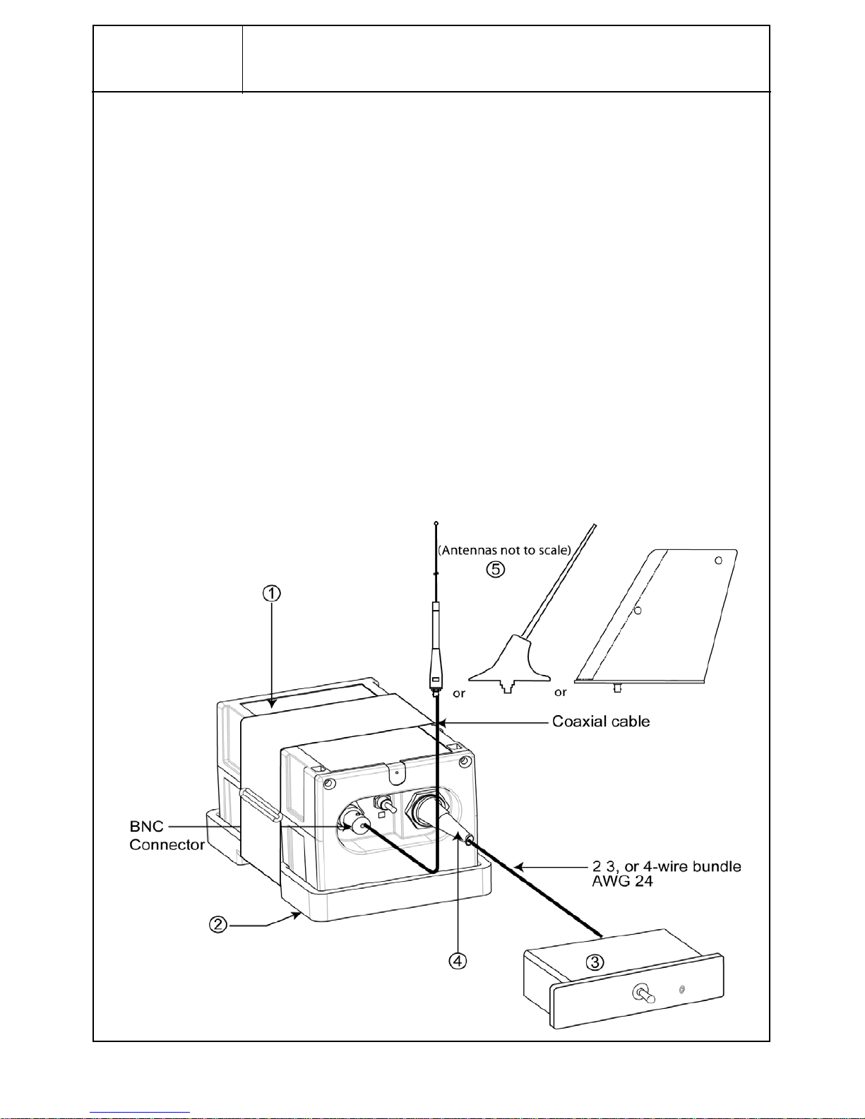
KANNAD INTEGRA System Presentation ............................................ 1
System overview ...................................................................................................1
Transmitter and bracket .........................................................................................2
Remote Control Panels (RCP) ...............................................................................3
RC100 KIT ..........................................................................................................3
RC102 KIT ..........................................................................................................4
RC200 .................................................................................................................4
RC300 / RC300 NVG ..........................................................................................5
RC600 NVG ........................................................................................................5
External antennas ..................................................................................................6
Registration ........................................................................................... 7
General ..................................................................................................................7
Registration in USA ...............................................................................................7
Registration in Canada ..........................................................................................8
ELT Installation ..................................................................................... 9
ELT and bracket installation recommendations .....................................................9
FAA Recommendations ......................................................................................9
TSO C126a Section 5 b. Application Data Requirements ...................................9
RTCA DO-182 Recommandations ......................................................................9
RTCA DO-204a Requirements ...........................................................................9
ELT location recommendations ........................................................................... 10
Bracket installation procedure .............................................................................10
Determine location and direction .......................................................................10
Fix the mounting bracket ...................................................................................12
ELT installation procedure ...................................................................................13
Antenna Installation ............................................................................. 15
Antenna Installation Recommendations .............................................................. 15
FAA Recommendations ....................................................................................15
RTCA DO-204 Recommendations for external antenna location ..................... 15
External Antenna Location ................................................................................15
Antenna installation procedure ............................................................................16
RCP installation ................................................................................... 18
RCP Installation Recommendations .................................................................... 18
RCP Installation Procedure .................................................................................18
RC100 ...............................................................................................................19
RC102 ...............................................................................................................21
RC200 ...............................................................................................................24
RC300 / RC300-NVG ........................................................................................26
RC600 NVG ......................................................................................................27
Outside Buzzer Installation ................................................................. 28
ELT Connection .................................................................................. 29
First power up procedure .................................................................... 29
ELT operational tests ...........................................................................................29
RCP operational tests ..........................................................................................30
406 and 121.5 MHz transmission test .................................................................31
406 MHz ............................................................................................................31

INITIAL INSTALLATION MANUAL
AF INTEGRA / AF-H INTEGRA
TABLE OF CONTENTS
TOC PAGE: 2
JUN 01/2011
121.5 MHz ........................................................................................................ 31
Outline dimensions and weights ......................................................... 33
Wiring diagrams .................................................................................. 48
Compatibility list for INTEGRA ELTs System ..................................... 53
Mounting brackets ............................................................................................... 53
Remote control panels (RCP) ............................................................................. 53
Outside buzzer .................................................................................................... 53
DIN-12 connector or programming dongles ........................................................ 53
External antennas ............................................................................................... 54

INITIAL INSTALLATION MANUAL
AF INTEGRA / AF-H INTEGRA
PAGE: 1
JUN 01/2011
1. Introduction
The instructions in this manual provide the information necessary for the initial
installation of AF INTEGRA / AF-H INTEGRA ELT system.
2. KANNAD INTEGRA System Presentation
A. System overview
NOTE: for details of approved part number of AF INTEGRA / AF-H INTEGRA
system, Refer to Section 12. Compatibility list for INTEGRA ELTs System,
page 53.
AF INTEGRA / AF-H INTEGRA system is composed of:
1. a transmitter;
2. a mounting bracket;
3. a remote control panel (RCP)(see note 1 page 2);
4. a DIN-12 connector or programming dongle to connect the RCP;
5. an approved external whip, rod or blade antenna.
Figure 1: ELT system description

INITIAL INSTALLATION MANUAL
AF INTEGRA / AF-H INTEGRA
PAGE: 2
JUN 01/2011
The most effective external antenna configuration is on top of the fuselage, aft
ofthewingorneartheverticalstabilizer.TheELTandmounting bracket should
be mounted in the aircraft as close as the antenna as practicable with a coaxial
cable towards the antenna as short as possible. The remote control panel(1) is
installed in the cockpit and connected to the ELT with a 2, 3, 4-wire bundle (not
supplied) according to the type of Remote Control Panel.
Note: (1) The RCP is optional only if the commands and controls of the
ELT are reachable and visible from the pilot seated position.
(RTCA DO-204A): "Equipment control and indicator installed for in-fli-
ght use shall be readily accessible from the cockpit crew position.
The cockpit crew shall have an unobstructed view of visual indicator
when in the normal seated position."
B. Transmitter and bracket
The ELT must be installed into one of the approved mounting brackets.
Itmay be installedon itsstandard mounting bracket or on a Universal Mounting
Bracket to re-use existing drilling for retrofit.
Refer to Section 12. Compatibility list for INTEGRA ELTs System, page 53 for
Part Numbers of approved mounting brackets.
The bracket installed near the tail is designed to fix the ELT with a Velcro®
strap. This enables quick removal of the ELT for maintenance or exchange.
Figure 2: INTEGRA ELT with Mounting Bracket

INITIAL INSTALLATION MANUAL
AF INTEGRA / AF-H INTEGRA
PAGE: 3
JUN 01/2011
C. Remote Control Panels (RCP)
Refer to Section 12. Compatibility list for INTEGRA ELTs System, page 53 for
Part Numbers of approved RCPs.
The RCP must be installed in the cockpit to monitor and control the ELT status.
It must be connected via a 2, 3, or 4-wire bundle to the DIN-12 socket of the
ELT (2, 3, 4-wire bundle is not supplied)
Note: An optional outside buzzer assembly can be connected to the ELT-
RCP. It gives an audio indication of emergency location transmitter
(ELT) activation. It is supplied with a mounting tray to install the buz-
zer on the aircraft. Figure 3: Outside buzzer
(1)RC100 KIT
The RC100 remote control panel is connected to the ELT via a 3-wire
cable equipped with a DIN-12 connector or optional programming dongle
on the ELT side and directly connected to the RCP on the other side.
Figure 4: RC100 Remote Control Panel

INITIAL INSTALLATION MANUAL
AF INTEGRA / AF-H INTEGRA
PAGE: 4
JUN 01/2011
(2) RC102 KIT
The RC102 remote control panel is connected to the ELT via a 2-wire
cable equipped with a DIN-12 connector or optional programming dongle
on the ELT side and directly connected to the RCP on the other side. 2
types of front panels are supplied in the kit. The appropriate front panel
should be choosen according to the place available on the aircraft’s
instrument panel.
Note: the optional outside buzzer is not available with this RCP.
Figure 5: RC102 Remote Control Panel
(3) RC200
The RC200 or RC200 NVG remote control panel is connected to the ELT
via a 3 or 4-wire bundle equipped with a DIN-12 connector or optional
programming dongle on the ELT side and a D-SUB Female 9 pins
connector on the other side.
Figure 6: RC200 Remote Control Panel

INITIAL INSTALLATION MANUAL
AF INTEGRA / AF-H INTEGRA
PAGE: 5
JUN 01/2011
(4) RC300 / RC300 NVG
The RC300 is connected to the ELT via a 4-wire bundle equipped with a
DIN-12 connector or optional programming dongle on the ELT side and a
D-SUB 9 PTS Male connector on the other side.
Figure 7: RC300 Remote Control Panel
(5) RC600 NVG
The RC600 NVG is connected to the ELT via a 5-wire bundle equipped
with a DIN-12 connector or optional programming dongle on the ELT side
and a female 22-pin connector on the other side.
Figure 8: RC600 NVG Remote Control Panel

INITIAL INSTALLATION MANUAL
AF INTEGRA / AF-H INTEGRA
PAGE: 6
JUN 01/2011
D. External antennas
The external antenna can be either of whip, rod or blade type according to
aircraft speed.
Connection to the ELT will be carried out with a 50 Ohm coaxial cable ended
with two male BNC connectors.
IMPORTANT NOTICE: KANNAD recommends a cable with radio electric
properties similar or better to those of a RG58 cable.
Note: the 50 Ohm coaxial cable and the male BNC connectors are not supplied.
Figure 9: Whip, rod and blade antennas
Whip antenna type
Rod antenna type Blade antenna type

INITIAL INSTALLATION MANUAL
AF INTEGRA / AF-H INTEGRA
PAGE: 7
JUN 01/2011
3. Registration
A. General
The ELT must be registered prior to installation onboard.
When a 406 MHz ELT is installed in an aircraft, it is imperative that the aircraft
owner register the ELT. Each 406 MHz ELT contains a unique identification
code that is transmitted to the satellite. This helps the “Rescue Coordination
Center” (RCC) determine whether an emergency has actually occurred. The
unique identification permits accessing a data base.
The registration card available from the local registration authority must be
completed and returned to this authority.
Any change of ownership shall also be declared and registered with the local
registration authority.
B. Registration in USA
Mail or Fax your registration form to:
NOAA/SARSAT
NSOF, E/SP3
4231 Suitland Road
Suitland, MD 20746
or Save Time! Register your beacon online at:
www.beaconregistration.noaa.gov
All online registrations will be entered into the National 406 MHz Beacon
Registration Database on the same day of entry. Registration forms received
via postal mail will be entered within 2 business days of receipt. For online
registrations, a confirmation letter with your completed registration information
form will be sent immediately via e-mail or fax (if provided). Confirmation letters
sent via postal mail should arrive within two weeks. Once your registration
confirmationis received,pleasereview allinformation.Any changesorupdates
to your registration information can be done via the internet, fax, e-mail or
postal mail. If you do not receive your registration confirmation from NOAA on
the same day you submit it over the internet or within two weeks if you submit
it by postal mail, please call NOAA toll-free at: 1-888-212-SAVE (7283) or
301-817-4515 for assistance.
After initial registration (or re-registration) you will receive a NOAA Proof of
Registration Decal by postal mail. This decal is to be affixed to the beacon and
should be placed in such a way that it is clearly visible. If for some reason you
do not receive the registration decal within two weeks, please call NOAA toll-
free at: 1-888-212-SAVE (7283) or 301-817-4515.
Failure to register, re-register (as required every two years), or to notify NOAA

INITIAL INSTALLATION MANUAL
AF INTEGRA / AF-H INTEGRA
PAGE: 8
JUN 01/2011
of any changes to the status of your 406 MHz beacon could result in penalties
and/or fines being issued under Federal Law. The owner or user of the beacon
is required to notify NOAA of any changes to the registration information at any
time. By submitting this registration the owner, operator, or legally authorized
agent declares under penalty of law that all information in the registration
information is true, accurate, and complete. Providing information that is
knowingly false or inaccurate may be punishable under Federal Statutes.
Solicitation of this information is authorized by Title 47 - Parts 80, 87, and 95 of
the U.S. Code of Federal Regulations (CFR). Additional registration forms can
be found on the NOAA-SARSAT website at:
www.sarsat.noaa.gov or at: www.beaconregistration.noaa.gov
C. Registration in Canada
Beacon information is held in the Canadian Beacon Registry maintained by the
National Search and Rescue Secretariat for use in search and rescue
operations. Online access to the Registry is available for all beacon owners to
register new beacons or to update their beacon information. You can add or
update your beacon information by accessing the registry directly, sending in a
completed registration form or by talking to one of our beacon registry
representatives.
You can access the registry:
• online: www.canadianbeaconregistry.com
• by fax: 1-613-996-3746
• by telephone: 1-800-727-9414 or 1-613-996-1616
The registration information must be updated when the aircraft ownership
changes as per the Canadian Airworthiness Notice AN B029 (refer to following
link):
http://www.nss.gc.ca/site/Emergency_Beacons/canadian_beacon_registry_e.asp
Additional information and registration forms can be found on the Canadian
NSS website at:
http://www.nss.gc.ca/site/cospas-sarsat/INTRO_e.asp

INITIAL INSTALLATION MANUAL
AF INTEGRA / AF-H INTEGRA
PAGE: 9
JUN 01/2011
4. ELT Installation
A. ELT and bracket installation recommendations
The ELT shall not be installed within 30cm (1 ft) of a compass or flux gate.
The distance between ELT and antenna shall be determined so that, according
to the coaxial cable choosen.
The ELT front panel should be easily accessible to connect the external
antenna and the remote control panel device and to check the ELT good
operation (controls and lights).
(1)FAA Recommendations
Installation must be made by qualified personnel in accordance with FAA
regulations. Duplicating a previous installation may not be acceptable.
Refer to:
FAA - Advisory Circular 43.13-2B (Acceptable Methods, Techniques,
and Practices - Aircraft Alterations), specifically, Chapters 1, 2, 11
and 13.
(2) TSO C126a Section 5 b. Application Data Requirements
"The conditions and tests for TSO approval of this article are minimum
performancestandards. Thoseinstallingthisarticle,on orina specifictype
or class of aircraft, must determine that the aircraft installation conditions
are within the TSO standards. TSO articles must have separate approval
for installation in an aircaft. The article may be installed only according to
14 CFR part 43 of the applicable airworthiness requirements".
(3) RTCA DO-182 Recommandations
"All ELT system components which must surviveto a crash intact,...should
be attached to the airframe in such a manner that the attachment system
can support a 100g load... in the plus and minus directions of the three
principal axes of the aircraft."
(4) RTCA DO-204a Requirements
"The ELT unit shall be mounted to primary aircraft load-carrying
structures such as trusses, bulkheads, longerons, spars or floor beams
(not aircraft skin) or a structure that meets the requirements of the
following test. The mounts shall have a maximum static local deflection
no greater than 2.5 mm when a force of 450 Newtons (l00 lbf) is applied
tothe mount inthe mostflexibledirection. Deflection measurementsshall
be made with reference to another part of the airframe not less than 0.3
m or more than 1.0 m from the mounting location. Typical approaches for
adding shelf and rail platform mounting provisions to aircraft structure as
shown an FAA Advisory circular 43.13-2(), Chapter 2."

INITIAL INSTALLATION MANUAL
AF INTEGRA / AF-H INTEGRA
PAGE: 10
JUN 01/2011
B. ELT location recommendations
KANNAD provides additional safety functions in the INTEGRA ELTs such as
built-in GPS and integral antenna.
If the link towards the external antenna is defective, the integral antenna,
protected by the high resistance housing of the ELT, may help to establish a
link towards the satellites COSPAS-SARSAT system.
However, KANNAD cannot control neither the environment of the ELT when a
crash occurs nor a too important metallic structure around the ELT. For these
reasons, KANNAD recommends to install the ELT in a location in such a way
that the vertical extension of the integral antenna is exposed to a RF
transparent window.
C. Bracket installation procedure
(1)Determine location and direction
Figure 10: KANNAD AF INTEGRA, axis of installation
- Determine the location of the ELT onboard according to paragraph A.
ELT and bracket installation recommendations page 9.
- The G-Switch axis shall be directed to sense the primary crash pulse

INITIAL INSTALLATION MANUAL
AF INTEGRA / AF-H INTEGRA
PAGE: 11
JUN 01/2011
along the longitudinal axis of the aircraft. Reference to the G-Switch is
given by the arrow "Flight direction" on the label affixed to the top of the
ELT.
(a) Fixed wing aircraft with AF INTEGRA
Refer to Figure 10: KANNAD AF INTEGRA, axis of installation.
The G-Switch sensor axis shall be pointed to sense the primary crash
pulse along the longitudinal axis of the aircraft (with maximum tolerance of
± 2°). Consequently, the AF INTEGRA shall be mounted:
- with the arrow of the "Flight direction" label pointed towards the front of
the aircraft;
- in any position parallel to the roll axis.
(b) Helicopters with AF INTEGRA
Refer to Figure 10: KANNAD AF INTEGRA, axis of installation.
AF INTEGRA may be installed on helicopter. The ELT unit should be
mounted (with maximum tolerance of ± 2°):
• with "Flight direction" arrow towards the front of the helicopter;
• with the front face connectors pointing downwards at a 45° angle to
the yaw axis;
• in any position parallel to the 45° axis.
(c) Helicopters with AF-H INTEGRA
Refer to Figure 11: KANNAD AF-H INTEGRA, axis of installation.
IMPORTANT: AF-H INTEGRA is designed to be mounted on board
helicopters only.

INITIAL INSTALLATION MANUAL
AF INTEGRA / AF-H INTEGRA
PAGE: 12
JUN 01/2011
Figure 11: KANNAD AF-H INTEGRA, axis of installation
The "Direction of Flight " arrow shall point towards the front or the bottom
of the helicopter (and not pointing 45° downwards):
- If the AF-H INTEGRA is installed with the "Direction of Flight " arrow
pointing towards the front of the helicopter, the ELT shall be mounted
with the upper side pointing towards the top of the helicopter.
- If the AF-H INTEGRA is installed with the "Direction of Flight " arrow
pointing towards the bottom of the helicopter, the ELT shall be installed
with the lower side pointing towards the front of the helicopter
(2) Fix the mounting bracket
- Drill 4 holes Ø 6 mm in the aircraft structure according to "Drilling mask":
Refer to Compact Mounting bracket (S1840502- 01), Outline
dimensions and weight, page 35 [Inner holes (1, 2, 3, 4) should be
preferred] or Refer to Compact Universal Mounting bracket (S1840502-
02), Outline dimensions and weight, page 36 according to mounting
bracket used.
- If the attachement system is not solid enough to withstand a 100G load
([ELT + bracket weight] x 100) on the bracket, a reinforcement plate (not
supplied) should be installed as shown Figure 12: Bracket installation in
order to be compliant with the RTCA DO-182 recommendation.
- Fix the bracket with the 4 screws, 8washers and 4 nylstop nuts supplied.
JUN 01/2011

INITIAL INSTALLATION MANUAL
AF INTEGRA / AF-H INTEGRA
PAGE: 13
JUN 01/2011
IMPORTANT: tighten to a torque between 4 and 5 Newton x meter.
Figure 12: Bracket installation
D. ELT installation procedure
1. Mount the transmitter on the bracket
• For AF INTEGRA or AF INTEGRA (ER), with "Flight Direction Arrow"
of the ELT pointed towards the front of the aircraft,according to Figure
10: KANNAD AF INTEGRA, axis of installation page 10.
• For AF-H INTEGRA or AF-H INTEGRA (ER), with "Flight Direction
Arrow" of the ELT pointed towards the front or downwards the
helicopter according to Figure 11: KANNAD AF-H INTEGRA, axis of
installation page 12.

INITIAL INSTALLATION MANUAL
AF INTEGRA / AF-H INTEGRA
PAGE: 14
JUN 01/2011
2. Slide the self-stripping strap through the buckle. Ensure the buckle is
correctly positioned (indifferently on right or left side of ELT)
regarding the horizontal center line of ELT as shown Detail A.
3. Fasten the self-stripping strap tightly.
Figure 13: Installing the transmitter on the bracket

INITIAL INSTALLATION MANUAL
AF INTEGRA / AF-H INTEGRA
PAGE: 15
JUN 01/2011
5. Antenna Installation
Use only whip, rod or blade approved antennas.
A. Antenna Installation Recommendations
(1)FAA Recommendations
Installation must be made by qualified personnel in accordance with FAA
regulations. Duplicating a previous installation may not be acceptable.
Methods for installing antenna are outlined in AC43.13-12, refer to:
FAA - Advisory Circular 43.13-2B (Acceptable Methods, Techniques,
and Practices - Aircraft Alterations), specifically, Chapters 1, 3, 11
and 13.
(2) RTCA DO-204 Recommendations for external antenna location
"ELT antennas should be located away from other antennas to avoid
disruption of antenna radiation patterns."
"Idealistically, for the 121.5 MHz ELT antenna, 2.5 meter separation is
sufficient separation from VHF communications and navigation receiving
antennas to minimize unwanted interferences."
"ELT antennas should be vertically polarized when the aircraft is in the
normal flight attitude."
"ELT antenna mounting surface should be able to whistand a static load
equal to 100 times the antenna weight applied at the antenna mounting
base in all directions."
"The antenna should be mounted as close to the respective ELT as
applicable. The proximity of the ELT antenna to any vertically-polarized
communications antenna shall be such as to minimize radio frequency
interference and radiation pattern distorsion of either antenna. Coaxial
cable connecting the ELT antenna installation should not cross the aircraft
production breaks and should have vibrations proof RF connectors on
each end. The coaxial connecting the ELT transmitter to the external
Antenna should be secured to the aircraft structure and when the coaxial
cable is installed and the connectors are mated, each end should be have
some slack."
(3) External Antenna Location
EUROCAE ED62A § 6.1.10.2
"The most effective antenna configuration for typical high-wing and low-
wing aircraft is an external antenna, on top of the fuselage, and aft of the
wing (high-wing), or near the vertical stabilizer (low-wing). Both ELT
antennas should be located away from other antennas to avoid disruption

INITIAL INSTALLATION MANUAL
AF INTEGRA / AF-H INTEGRA
PAGE: 16
JUN 01/2011
of antenna radiation patterns. Detuning of the 121.5 MHz antenna may be
requiredavoid the effects of radiated inter-modulation products which may
bepossiblefrom non-operating 121.5MHzELTsexposedto high levels of
RF energy.
Idealistically, for the 121.5 MHz ELT antenna, 2.5 meter separation is
sufficient separation from VHF communications and navigation receiving
antennas to minimize unwanted interference. The 406 MHz ELT antenna
should be positioned at least 0.8 m from VHF communications and
navigation receiving antennas to minimize interference.
External antennas, which have been shown to be compatible with
particular ELT will either be part of the ETSO/TSO'd ELT or will be
identified in the ELT manufacturer's installation instructions.
Recommended methods for installing antenna are outlined in FAA AC
43.13-2B. The Antenna should be mounted as close to the respective ELT
as practicable."
B. Antenna installation procedure
The antenna must be mounted on the top of the aircraft to assure maximum
visibility of satellites. The upper aft portion of the fuselage should be preferred.
It should be mounted away from projections such as a propeller, tail surfaces,
or the shadow of large antennas. It is the responsibility of the installation
agency to determine the appropriate and adequate antenna installation.
Locate a position on the fuselage according to Section (2) RTCA DO-204
Recommendations for external antenna location, page 15:
A double plate may be necessary for the antenna to meet rigidity specifications
in Section (2) RTCA DO-204 Recommendations for external antenna location,
page 15.
A 9 Kilogram force (20 pound force) applied in all direction should not cause an
appreciable distorsion in the aircraft skin.
Each of the approved antennas requires a ground plane. On fabric-covered
aircraft or aircraft with other types on nonmetallic skins, a ground plane must
be added. This can be accomplished by providing a number of metal foil strips
inaradialpositionfromthe antennabaseandsecuredunderthefabricor wood
skin of the aircraft. The length of each foil radial should be at least equal to the
antennalengthandwidthatleast1inchduetothe diameteroftheantenna.The
ground plane must be connected to the shield of the antenna connector.
Other manuals for AF INTEGRA
1
This manual suits for next models
1
Table of contents
Other Kannad Transmitter manuals

Kannad
Kannad SafeLink AIS SART2 User manual

Kannad
Kannad 406 AF User manual

Kannad
Kannad AF INTEGRA User manual

Kannad
Kannad 406 AF-COMPACT User manual

Kannad
Kannad 406 AF-COMPACT Service manual

Kannad
Kannad 406 AP-H User manual

Kannad
Kannad 406 AP User manual

Kannad
Kannad RC200 Guide

Kannad
Kannad 406 AF-COMPACT User manual