AMX SoftKey TX-SK+ User manual

instruction manual
Transmitters
TX-SK+
SoftKey Transmitter

AMX Limited Warranty and Disclaimer
AMX Corporation warrants its products to be free of defects in material and workmanship under normal use for three
(3) years from the date of purchase from AMX Corporation, with the following exceptions:
• Electroluminescent and LCD Control Panels are warranted for three (3) years, except for the display and touch
overlay components that are warranted for a period of one (1) year.
• Disk drive mechanisms, pan/tilt heads, power supplies, and MX Series products are warranted for a period of one
(1) year.
• AMX Lighting products are guaranteed to switch on and off any load that is properly connected to our lighting
products, as long as the AMX Lighting products are under warranty. AMX Corporation does guarantee the
control of dimmable loads that are properly connected to our lighting products. The dimming performance or
quality cannot be guaranteed due to the random combinations of dimmers, lamps and ballasts or transformers.
• Unless otherwise specified, OEM and custom products are warranted for a period of one (1) year.
• AMX Software is warranted for a period of ninety (90) days.
• Batteries and incandescent lamps are not covered under the warranty.
This warranty extends only to products purchased directly from AMX Corporation or an Authorized AMX Dealer.
All products returned to AMX require a Return Material Authorization (RMA) number. The RMA number is
obtained from the AMX RMA Department. The RMA number must be clearly marked on the outside of each box.
The RMA is valid for a 30-day period. After the 30-day period the RMA will be cancelled. Any shipments received
not consistent with the RMA, or after the RMA is cancelled, will be refused. AMX is not responsible for products
returned without a valid RMA number.
AMX Corporation is not liable for any damages caused by its products or for the failure of its products to perform.
This includes any lost profits, lost savings, incidental damages, or consequential damages. AMX Corporation is not
liable for any claim made by a third party or by an AMX Dealer for a third party.
This limitation of liability applies whether damages are sought, or a claim is made, under this warranty or as a tort
claim (including negligence and strict product liability), a contract claim, or any other claim. This limitation of
liability cannot be waived or amended by any person. This limitation of liability will be effective even if AMX
Corporation or an authorized representative of AMX Corporation has been advised of the possibility of any such
damages. This limitation of liability, however, will not apply to claims for personal injury.
Some states do not allow a limitation of how long an implied warranty last. Some states do not allow the limitation or
exclusion of incidental or consequential damages for consumer products. In such states, the limitation or exclusion of
the Limited Warranty may not apply. This Limited Warranty gives the owner specific legal rights. The owner may
also have other rights that vary from state to state. The owner is advised to consult applicable state laws for full
determination of rights.
EXCEPT AS EXPRESSLY SET FORTH IN THIS WARRANTY, AMX CORPORATION MAKES NO
OTHER WARRANTIES, EXPRESSED OR IMPLIED, INCLUDING ANY IMPLIED WARRANTIES OF
MERCHANTABILITY OR FITNESS FOR A PARTICULAR PURPOSE. AMX CORPORATION
EXPRESSLY DISCLAIMS ALL WARRANTIES NOT STATED IN THIS LIMITED WARRANTY. ANY
IMPLIED WARRANTIES THAT MAY BE IMPOSED BY LAW ARE LIMITED TO THE TERMS OF THIS
LIMITED WARRANTY.
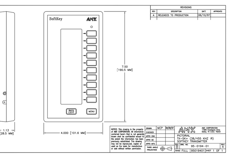
Table of Contents
i
T
X-SK+ SoftKey Transmitter
Table of Contents
Introduction ...............................................................................................................1
Product Specifications ...................................................................................................... 2
Pushbuttons and Menu Options .............................................................................3
LCD Screen....................................................................................................................... 3
Battery display.......................................................................................................................... 3
Pushbuttons ...................................................................................................................... 3
Menu ........................................................................................................................................ 3
BACK LIGHT............................................................................................................................ 3
Power ....................................................................................................................................... 3
AXCESS Programming ..................................................................................................... 3
SKDesign Programming.................................................................................................... 3
Universal IR....................................................................................................................... 4
RS-232 Control.................................................................................................................. 4
Setup Page........................................................................................................................ 4
Previous ................................................................................................................................... 5
Contrast.................................................................................................................................... 5
Baud......................................................................................................................................... 5
Sleep timeout ........................................................................................................................... 5
Back light timeout..................................................................................................................... 6
IR/RF (serial number 190-XXXX models only)......................................................................... 6
IR (serial number 194-XXX-XXXX models only) ...................................................................... 6
RF (serial number 194-XXX-XXXX models only)..................................................................... 6
Display channels ...................................................................................................................... 7
RS-232 master/control port ...................................................................................................... 7
System information .................................................................................................................. 7
Testing............................................................................................................................... 8
Check transmission settings .................................................................................................... 8
Check transmission codes ....................................................................................................... 8
Test downloading ..................................................................................................................... 8
Connecting Cables ............................................................................................................ 9
Recharging the batteries .......................................................................................................... 9
Programming the unit............................................................................................................... 9
Programming ..........................................................................................................11
General Information......................................................................................................... 11
Supported AXCESS Keywords ....................................................................................... 11
Operator Keywords ......................................................................................................... 20

Introduction
1
T
X-SK+ SoftKey Transmitter
Introduction
The TX-SK+ SoftKey wireless transmitter (FIG. 1) is hand-held programmable device contains
easy-to-use menus that support a wide variety of wireless audiovisual equipment. It includes 10
variable-function SoftKey Pushbuttons.
TX-SK+ wireless transmitter with serial number 194-XXX-XXXX support 455 kHz IR control.
The label containing the serial number is located on the back panel of the TX-SK+ transmitter.
FIG. 1 TX-SK+ SoftKey wireless transmitter

Introduction
2TX-SK+ SoftKey Transmitter
Product Specifications
TX-SK+ Wireless Transmitter
Dimensions (HWD) 7.5" x 4" x 1.13"
(19.05 cm x 10.16 cm x 2.86 cm)
Weight 16.9 oz (462 grams) without batteries
Enclosure Black injection-molded plastic
Power • Rechargeable NICAD battery pack
• Automatic Power - panel goes to sleep when not in use; press any
pushbutton to wake up panel.
Pushbuttons 12 black menu/operation pushbuttons:
• 10 variable-function SoftKey Pushbuttons
• BACK LIGHT Pushbutton - lights LCD screen (adjustable).
• MENU Pushbutton - opens the Main Menu selections.
Display • Low Battery/Charging Indicator - LOW BATT flashes when the battery needs
to be charged.
• Front-Panel Setup - configures TX-SK+ parameters such as sleep time and
baud rates.
• Graphic Symbols - library of symbols for tape transport options such as play,
stop, etc., and arrows that can be integrated with menu text.
Control Types • RF/IR Transmission - supports both RF and IR frequencies.
• Universal IR Control - manufacturer's IR codes can be stored in memory and
mixed with AMX format IR and RF codes using program control.
• RS-232 Master/Control Port - programmable for bi-directional RS-232 control
commands using the RS-232 Master/Control port.
Signal Types • 38 kHz IR frequency (serial number 190-XXXX models only)
• 38 kHz or 455 kHz IR frequencies (serial number 194-XXX-XXXX models
only)
• 303.875 MHz RF signal
Program Memory 24K of permanent user program memory.
• Compiled code and source code can be stored for most programs.
• Program memory is not lost if the NICAD batteries are removed or
discharged.
LED Red LED indicator for signal transmission
Supplied accessories • Stereo mini-plug connector
• 12 VDC (800 mA) battery power supply (US only)
• Rechargeable NICAD Batteries - 8-hour charge provides approximately 14
hours of operation. The TX-SK+ can also be used with the supplied DC
battery charger/power supply.
Optional accessories • CC-232 TX-SK+ Programming Cable with DB-9 male connector
• CC-232 TX-SK+ Programming Adapter Cable with DB-9 female connector
• Alternate international radio frequencies available
• SKDesign - programming software that allows you to create custom panel
layouts.
• AXCESS Software Program - creates custom TX-SK+ programs to control a
wide variety of audiovisual equipment.

Pushbuttons and Menu Options
3
T
X-SK+ SoftKey Transmitter
Pushbuttons and Menu Options
This section describes the pushbuttons and menus options.
LCD Screen
The TX-SK+ has a vertical backlit liquid crystal display (LCD) screen that can be programmed
with up to 30 text lines. Each TX-SK+ pushbutton can have up to three lines of text (eight
characters per line). Text lines can be highlighted using reverse video.
The page title can be set to display at the top or bottom of the LCD.
Battery display
The bottom display line will flash LOW BAT when approximately 1 to 3 hours of operation remain.
The back light is disabled in this mode. When you recharge the battery, the CHARGING message
flashes. A CHARGED message appears when charging is complete.
The TX-SK+ goes into sleep mode if the battery level is below minimum power level requirements.
Pushbuttons
There are 12 menu/operation pushbuttons on the TX-SK+. One pushbutton opens the main menu,
and the other toggles the back light on or off. The 10 remaining menu pushbuttons can be
programmed to display new menus, transmit wireless commands, or both.
Menu
The MENU pushbutton opens the main menu.
BACK LIGHT
The BACK LIGHT pushbutton toggles the back light on or off. When the back light is on, it stays
on for the user-defined time period. The time period can be set from 15 seconds to 5 minutes with
the BACK LIGHT TIMEOUT option in the special SETUP page.
Power
The TX-SK+ does not have an on/off switch. Instead, the panel uses an intelligent sleep mode when
it's not being used. The TX-SK+ is equipped with a timer that deactivates the display and back light
when it is inactive for a preset time. If any one of the TX-SK+'s pushbuttons are pressed, the panel's
back light, display, and current menu are activated.
AXCESS Programming
You can program the TX-SK+'s menus, text, operating logic, and wireless code transmission with
the AXCESS software program.
SKDesign Programming
The TX-SK+ uses a graphical approach to programming. You can create menus by adding text and
commands to pages in DOS format with your PC. Pages can be saved to disk to create a library of
pre-designed menus. Panel operation can be viewed on-screen from a simulated TX-SK+, and

Pushbuttons and Menu Options
4TX-SK+ SoftKey Transmitter
pages can be printed on most Windows-compatible printers. SKDesign automatically creates
AXCESS program files that you can store on disk or download to a TX-SK+ transmitter.
Universal IR
The TX-SK+ typically transmits AMX formatted IR and RF control codes. The TX-SK+ can also
be programmed to transmit IR codes for other manufacturers. This feature allows the TX-SK+ to
act as a mini-control system that can control VCRs, audio components, and video projectors.
Manufacturer codes (up to 128) are sent to the TX-SK+ using the AMX IRLIB library software.
AXCESS commands and IRLIB files for this feature are addressed as device 2 in TX-SK+
transmitter.
RS-232 Control
The TX-SK+'s RS-232 Master/Control port can be used for direct bi-directional communication
with an RS-232 controlled source.
Setup Page
Press the top pushbutton and MENU button simultaneously to open the Setup Page menu shown in
FIG. 2. The Setup page contains options to program for TX-SK+. Press EXIT or the MENU
pushbuttons to return to normal operation.
CONTRAST, BAUD, SLEEP TIMEOUT, BACKLIGHT TIMEOUT and SYSTEM
INFO displays a new sub-menu to select options.
IR, RF, DISPLAY CHANNELS and MASTER PORT stay on the SETUP page, toggling
selections when the associated pushbutton is pressed.
FIG. 2 Setup Page
BACK
LIGHT MENU
CONTRAST
BAUD
SLEEP
BACKLITE
IR
RF
DISPLAY
SYSTEM
EXIT
12
9600
TIMEOUT
TIMEOUT
CHANNELS
ON
OFF
OFF
INFO
MASTER
PORT
ENABLED

Pushbuttons and Menu Options
5
T
X-SK+ SoftKey Transmitter
Previous
Sub-menus include the PREVIOUS selection (FIG. 3) located at the bottom pushbutton. Press
PREVIOUS to return to the SETUP menu.
Contrast
Press UP or DOWN pushbuttons (FIG. 4) to adjust the LCD contrast from 1 (no contrast) to 20 (full
contrast). The typical contrast setting is 10 to 17.
Baud
Press the pushbutton adjacent to the appropriate baud rate (FIG. 5) to set the baud rate, and port
type as a master or RS-232 control port. The current baud rate appears in the top-left corner of the
LCD.
Sleep timeout
Press the UP or DOWN pushbutton (FIG. 6) to set the sleep time from 15 seconds to 5 minutes. If
the SLEEP time is set to 2 minutes, the panel turns off when the TX-SK+ is inactive for 2 minutes.
FIG. 3 Previous pushbutton
FIG. 4 Contrast pushbuttons
FIG. 5 Baud rate pushbuttons
FIG. 6 Sleep timeout pushbuttons
PREVIOUS
UP
DOWN
12
9600
600
1200
2400
4800
300
9600
DOWN
2 MINS
0 SECS
UP

Pushbuttons and Menu Options
6TX-SK+ SoftKey Transmitter
Back light timeout
Press UP or DOWN pushbutton (FIG. 7) to set the back light timer from 15 seconds to 5 minutes. If
the BACK LIGHT TIMEOUT is set to 2 minutes, the back light turns off when the TX-SK+ is
inactive for 2 minutes.
IR/RF (serial number 190-XXXX models only)
Press the IR or RF pushbutton (FIG. 8) to toggle IR or RF code transmission on or off. Off mode
disables all IR or RF code transmissions.
IR (serial number 194-XXX-XXXX models only)
Press the IR pushbutton (FIG. 9) to set the IR frequency to 38 KHz, 455 KHz, or to off. Off mode
disables all IR transmissions.
RF (serial number 194-XXX-XXXX models only)
Press the RF pushbutton (FIG. 10) to toggle RF transmission on or off. Off mode disables all RF
transmissions.
FIG. 7 Back light timeout push-buttons
FIG. 8 IR/RF pushbuttons
DOWN
2 MINS
0 SECS
UP
IR
RF ON
OFF
The AMX label containing the serial number is located on the back panel of the TX-
SK+ transmitter.
FIG. 9 IR pushbuttons
FIG. 10 RF pushbuttons
IR
RF ON
OFF
IR
RF ON
OFF

Pushbuttons and Menu Options
7
T
X-SK+ SoftKey Transmitter
Display channels
The TX-SK+ can show device and channel numbers transmitted when a button is pressed. If
DISPLAY CHANNELS (FIG. 11) is on, the code transmitted is shown on the bottom line of screen.
If [1,32] appears on the LCD, the AMX format code is set for device 1, and channel number 32.
RS-232 master/control port
The RS-232 Master/Control port pushbutton (FIG. 12) sets the RS-232 Master/Control port on the
TX-SK+. Set the port to ENABLED to upload or download AXCESS programs via a PC-to-AMX
programming cable connection. Set the port to DISABLED to transmit RS-232-control signals.
System information
The System Information page (FIG. 13) shows the operating status of the TX-SK+.
CURRBATT-shows current battery level. A 210-220 setting indicates fully charged
batteries
HIGHBATT-not used
LOWBATT-not used
FLAGS-not used
NV FLAGS-not used
VERSION-shows the TX-SK+ software version
FIG. 11 Display channels pushbutton
FIG. 12 RS-232 Master/Control port pushbutton
FIG. 13 System information pushbuttons
DISPLAY
ON
CHANNELS
MASTER
DISABLED
PORT
CURRBATT
255
165
2
1
215
2.23
HIGHBATT
LOWBATT
FLAGS
NV_FLAGS
VERSION

Pushbuttons and Menu Options
8TX-SK+ SoftKey Transmitter
Testing
These instructions describe how to check transmission settings, transmission codes, and
downloading data to the TX-SK+.
Check transmission settings
If no transmitted wireless codes are received by the system when a button is pressed:
1. Press MENU and top pushbutton simultaneously to open the SETUP page.
2. Verify the IR or RF frequency is set correctly. If not, set the RF option to on. For TX-SK+
transmitters with the serial number 190-XXXX, set the IR option on. For transmitters with the
serial number 194-XXX-XXXX, set the IR option to 38 KHz or 455 KHz as required.
Check transmission codes
If specific transmit codes are not received or functions do work correctly:
1. Press the MENU and top pushbuttons simultaneously to open the SETUP page.
2. Set DISPLAY CHANNELS to ON.
3. Press the desired pushbutton and note the device and channel number that appears on the
bottom line.
4. Check AXCESS or SKDesign program to verify the device and channel number is correct.
Test downloading
If the PC screen indicates MASTER NOT PRESENT when you launch the AXCESS program or
IRLIB file program:
1. Verify that MASTER PORT is ENABLED.
2. Verify that the PC COM port baud rate matches the TX-SK+. All IRLIB files are sent as device
2.
3. Verify the TX-SK+ is not in sleep mode.
The IR on/off and RF on/off settings only apply to codes transmitted to AMX
receivers. The IR or RF options should be set to off if the corresponding AMX
receiver is not used in the system. The TX-SK+ will transmit manufacturer's IR codes
regardless of the IR setting.
If the Transmit LED does not light when a pushbutton is pressed, the function may not
be present in the program (no code sent).

Pushbuttons and Menu Options
9
T
X-SK+ SoftKey Transmitter
Connecting Cables
These instructions describe how to recharge the batteries, and to program the TX-SK+ transmitter.
Recharging the batteries
Use the 12 VDC (800 mA) power supply to recharge the TX-SK+ batteries. Charging is controlled
by an internal microprocessor to prevent overcharging the battery. The DC power supply is wired
with 12 VDC to tip, and GND (-) to sleeve
Programming the unit
There are two types of cables you can purchase to download AXCESS or SKDesign programs to
the TX-SK+. The CC-232 DB-9 (female) connector-to-stereo mini-plug cable connects directly to
your PC's serial port and the TX-SK+. The CC-232 DB-9 (male) connector-to-stereo mini-plug
adapter cable connects to an AMX programming cable and to the TX-SK+. Figure 14 shows the
cable construction and solder-side pinout views.
The following table lists the pinouts for the cables.
FIG. 14 CC-232 TX-SK+ Programming Cable construction and solder-side pinout views
CC-232 DB-9 connectors and stereo mini-plug pinouts
DB-9 (male) connector DB-9 (female) connector Cable Stereo mini-plug
Signals Pins Signals Pins Colors Pins
GND 5 GND 5 Shield Sleeve
RXD 3 RXD 2 Red Tip
TXD 2 TXD 3 Black Ring

Pushbuttons and Menu Options
10 TX-SK+ SoftKey Transmitter

Programming
11
T
X-SK+ SoftKey Transmitter
Programming
General Information
The TX-SK+ supports:
2 dim arrays
Up to 10 waits
up to 5 concurrent TOs
up to 5 concurrent PULSEs
24Kb of memory
Up to 22 pages
Up to 5 nested levels
Does not support programs complied with separate DEFINE_CALL list.
Supported AXCESS Keywords
The following Axcess keywords are supported by the TX-SK+ (rev 2.26 and higher):
AXCESS Keywords
CALL To tell Axcess to execute a subroutine, use the CALL keyword and the
name of the subroutine in single quotes.
For example, to execute the subroutine LIGHTS OFF, type the following
where you want the CALL to occur:
CALL 'LIGHTS OFF'
When Axcess executes the CALL, program execution jumps to the first
line inside the braces of the DEFINE_CALL. The subroutine is executed
only once, and then Axcess returns to the statement directly following the
CALL statement.
CANCEL_ALL_WAIT CANCEL_ALL_WAIT nullifies every WAIT currently in the list.
CANCEL_WAIT CANCEL_WAIT completely nullifies a WAIT, removing it from the wait
list.
CREATE_BUFFER Use the CREATE_BUFFER keyword to create a buffer.
This keyword can only appear in the DEFINE_START section of your
program, and has the following syntax:
CREATE_BUFFER device, array
CREATE_BUFFER directs Axcess to place any strings received from the
specified device into the specified array. When Axcess places the byte
into the array, Axcess increments the length value for the array and then
places the byte at the end of the array. When the array is full, all bytes in
the array are shifted to make room for the new byte at the end.
Though the array is acting as a buffer, it is still an array and can be
treated as one. You can access its individual locations, send it to a
device, assign it to other arrays, assign other arrays to it, and use key-
words to manipulate the array.

Programming
12 TX-SK+ SoftKey Transmitter
AXCESS Keywords (Cont.)
DEFINE_CALL
(without parameters)
In Axcess, subroutines are created using the DEFINE_CALL statement.
The subroutine name follows the DEFINE_CALL keyword, enclosed in
single quotes. There are certain restrictions for these subroutine names:
• They cannot be previously defined constants or variables.
• They cannot be names that have already been assigned to BUFFERS
or WAITs.
• They are case-sensitive. For example, Test and TEST are not the
same.
Subroutines must be defined before they can be used. For this reason,
DEFINE_CALLS are typically placed right before the DEFINE_START
section of the program. Here is the format:
DEFINE_CALL 'subroutine name'
{
(* The subroutine goes here *)
}
Spaces in the subroutine name are allowed because it is a string literal.
Notice that the subroutine's code is enclosed in braces. No matter how
long the subroutine is, it must be in this format.
DEFINE_CONSTANT Constants are identifiers whose values remain unchanged throughout
the entire program. The process of defining them is very similar to defin-
ing devices. Assigning a value to an identifier in this section locks that
value to the identifier for the entire program, making it possible to use
descriptive names instead of just numbers in your program.
In your system, the VCR, CD player, and cassette deck devices have
channels that activate the various transport functions, such as Play and
Stop. As a general rule, Play is usually channel 1 and Stop is channel 2.
You could define these channel numbers as constants in your program to
make it more readable.
DEFINE_CONSTANT
PLAY = 1 (* VCR, CD AND CASS CONSTANTS *)
STOP = 2
PAUSE = 3
FFWD = 4
REW = 5
FSRCH = 6
RSRCH = 7
REC = 8
SCREEN_UP = 1 (* RELAY CONSTANTS *)
SCREEN_DN = 2
SYSTEM_POWER = 3
DRAPES_OPEN = 4
DRAPES_CLOSE = 5
DRAPES_STOP = 6
AMP_POWER = 7
LIGHT_FULL = 1 (* LOW VOLTAGE LIGHTING PRESETS
*)
LIGHT_MED = 2
LIGHT_LOW = 3
LIGHT_OFF = 4
VPROJ_IN_1 = 11
VPROJ_IN_2 = 12
VPROJ_IN_3 = 13
VPROJ_IN_4 = 14
The value of the constant PLAY is now set to 1. Also, STOP has a value
of 2. Both of these values cannot be changed anywhere in the program.
With these constants set, if you need to activate the play function of the
VCR later in your program, use the constant PLAY, and Axcess knows to
use channel 1.

Programming
13
T
X-SK+ SoftKey Transmitter
AXCESS Keywords (Cont.)
DEFINE_CONSTANT (Cont.)
More than one constant can have the same number. For example, PLAY
and FWD can both equal 1. You may see this if two cards do not have the
same channels for the same functions. For example, PLAY on the VCR
control card might be channel 1, and FWD on the slide control card could
also be channel 1.
By definition, the same constant cannot reference more than one num-
ber. This might seem obvious, but this type of error could work its way
into larger programs. If you make this mistake, Axcess notifies you with a
DUPLICATE SYMBOL error message upon compiling.
DEFINE_DEVICE When you start writing a program, label each device in the system. Each
device on AXlink must have a unique device number. For example, card
1 may have device number 1, and card 2 may have device number 2.
Whenever you use this device name in your program, Axcess will auto-
matically use the corresponding device number to reference the device.
This is the function of the DEFINE_DEVICE section. It is placed at the
beginning of the program, and allows you to name the devices.
However, with a long list of devices connected to AXlink, these numbers
can be difficult to remember. Assigning actual names to these devices is
much easier.
The first step in writing a program is defining the devices in your system.
For example, you have a VCR, a CD player, and a cassette deck, and
you are controlling them with the first three cards in your CardFrame.
These cards have device numbers 1, 2, and 3. You also need to control a
projection screen, some drapes, and lights. Two relay cards, one in slot 4
and one in slot 5, will handle these (the first card handles both the screen
and drapes). A Touch Panel will be used to control all of these devices.
Your DEFINE_DEVICE section should look like this:
Note: The devices included in this code are used for example purposes
only. It is not a specific recommendation or endorsement.
DEFINE_DEVICE
VCR = 1 (* AXC-IR/S: VCR *)
CD = 2 (* AXC-IR/S: CD PLAYER *)
CASS = 3 (* AXC-REL8: VCR *)
RELAY = 4 (* AXC-REL8: SCREENS AND DRAPES
*)
LIGHTS = 5 (* AXC-REL8: LOW VOLTAGE
LIGHTING *)
VPROJ = 6 (* AXC-IR/S: PROJECTOR *)
TP = 128 (* AXU-CVA COLOR VIDEO PANEL *)
From this point on, you can reference device 1 with the name VCR,
device 2 with the name CD, and so on.
The Push window at the bottom of the screen is changed. If the devices
in the previous example are on AXlink, Axcess modifies the window to
use the given device name instead of the device's number. This provides
a quick reference tool for future programming.
There is one more reason for using DEFINE_DEVICE. When you com-
pare devices using the Compare Current Devices... option in the Diag-
nostics menu, Axcess checks all the devices listed under
DEFINE_DEVICE. Next, it checks which devices are on AXlink. Axcess
then tells you the devices that you did not define in your program. These
devices cannot be used or referenced until they are defined, so check
that all devices are under this heading.
AMX encourages the practice of starting control panel device numbers at
device 128. This includes radio frequency (RF) receivers, touch panels,
softwire panels, and all other control panels and receivers.

Programming
14 TX-SK+ SoftKey Transmitter
AXCESS Keywords (Cont.)
DEFINE_LATCHING A latching channel is a channel that only changes its state once per
push. If a latching channel is activated by a TO keyword, it changes its
state; when the TO is stopped, by releasing the button that started it, the
channel does not go back to its previous state (like a momentary chan-
nel). The channel stays either on or off. The status of a latching channel
will reflect the on/off state of the channel. Here is an example:
DEFINE_LATCHING
[RELAY,SYSTEM_POWER] (* defined as latching *)
[VCR,PLAY]..[VCR,REWIND] (* defines a range of device-
channels as latching *)
VAR1 (* defined as latching *)
DEFINE_MUTUALLY_EXCLUSIVE When a channel is turned on in a mutually exclusive set, it activates its
physical output as long as the button is pressed. When the button is
released, the physical output stops. The status, however, does not work
the same way. Even after the physical output stops, the status still indi-
cates the channel is on until another channel in the mutually exclusive
set is activated. The status is left on to indicate which channel in the set
was last activated. This is sometimes called last button pressed feed-
back. When a channel or variable in this set is activated, all the other
members of the set are turned off beforehand. This is called break before
make logic. This prevents an accidental activation of more than one
channel at the same time, which could cause serious damage to some
devices. Members of a mutually exclusive set are placed in parentheses
underneath the DEFINE_MUTUALLY_EXCLUSIVE keyword. The double
period (..) shortcut specifies a range of device-channels to be defined as
mutually exclusive. For example:
DEFINE_MUTUALLY_EXCLUSIVE
([RELAY,SCREEN_UP],[RELAY,SCREEN_DOWN]) (* defines two
channels as
mutually
exclusive *)
([RELAY,DRAPE_OPEN]..[RELAY,DRAPE_STOP])(* defines a
range of
channels
as mutually
exclusive *)
DEFINE_PROGRAM Define_Program marks the beginning of mainline, telling the compiler
that the following statements make up the actual executing program.
Before beginning the main program, you must have the
DEFINE_PROGRAM header. This header tells Axcess you are begin-
ning the actual program at this point. It is used like this:
DEFINE_PROGRAM (* Your program starts here *)
The most important feature of mainline is that it runs in a continuous
loop. While most programming languages have a beginning and an end,
mainline is like a circle: when the Central Controller gets to the end, it
loops back to the top and passes through it again.
DEFINE_START DEFINE_START marks the section of programming that will be executed
only once immediately following power-up or system reset. They cannot
be executed again until another Axcess power-up. The keyword TO can-
not be used in the DEFINE_START section; instead, use ON, OFF, or
PULSE. For information on these keywords, refer to Changing the State
of a Channel section on page 16.
When the Axcess Control System is turned on, the program that was last
loaded into the Central Controller is in operation, and is waiting for input
from the user. However, you can tell Axcess to run a series of statements
immediately when the system is turned on.
In your program, you may want to reset all three decks to stop (using
SYSTEM_CALLs), turn on the lights, open the drapes, and raise the
screen when Axcess is powered up.

Programming
15
T
X-SK+ SoftKey Transmitter
AXCESS Keywords (Cont.)
DEFINE_START (Cont.) For example:
DEFINE_START
PULSE[LIGHTS,LIGHT_FULL]
PULSE[RELAY,DRAPES_OPEN]
PULSE[RELAY,SCREEN_UP]
SYSTEM_CALL 'FUNCTION' (VCR,STOP,Ø)
SYSTEM_CALL 'FUNCTION' (CD,STOP,Ø)
SYSTEM_CALL 'FUNCTION' (CASS,STOP,Ø)
Any resetting of variable values should be done in this section. Remem-
ber, variables retain their values even if the system is powered down.
DEFINE_TOGGLING To make a channel toggling, it must be defined as both mutually exclu-
sive and toggling. The DEFINE_TOGGLING section is usually located
directly after the DEFINE_MUTUALLY_EXCLUSIVE section. Here is an
example:
DEFINE_TOGGLING
[RELAY,SCREEN_UP]
[RELAY,SCREEN_DOWN]
DEFINE_VARIABLE Variables are places to store data that will change as the program is exe-
cuted. Think of a variable as a random container, nearly anything can be
placed in it. For example, a variable can represent any number from 0 to
65,535; variables cannot hold a negative number. If one variable is sub-
tracted from another, the result will always be positive. If you subtract a
larger number from a smaller number, the result wraps around at 65,535.
For example, 10-20 = 65,525.
DEFINE_VARIABLE
TEMP (* Single variables *)
BUFFER[1Ø] (* Array variables *)
INTEGER CAM_PRESET[1Ø] (* Integers and variables *)
When the system is turned off, variables retain their values. Resetting
varaiables must be done manually in the DEFINE_START section.
In your first program, you will not be using variables, but keep the
DEFINE_VARIABLE header because you will be using them in the
future.
ELSE If the corresponding IF statement is false, the program will jump to this
section of the IF...ELSE set of statements.
See IF for details.
GET_BUFFER_CHAR This keyword is used to remove characters from a buffer. It has a two-
part operation:
• First, it retrieves the first character in the buffer for your own utilization.
This creates the same effect as if you retrieved the first storage
location of a normal string array.
• Second, it removes that character from the buffer, causing all the other
characters to shift up one place. The second character is now the first,
the third is now the second, and so on.
Here is the syntax:
result = GET_BUFFER_CHAR (array)
The parameter passed to GET_BUFFER_CHAR must be an array, but
does not need to be a buffer. The keyword will operate identically in
either case. Only one byte (character) will be returned, and this value
can be assigned to a variable, array, or a cell in an array.

Programming
16 TX-SK+ SoftKey Transmitter
AXCESS Keywords (Cont.)
IF The IF statement provides conditional branching of program flow.
Every IF statement must be followed by an expression enclosed in
parentheses. This provides the beginning of a conditional execution of
statements. For example:
IF (expression)
(* Statement 1 *)
If the expression is true, Axcess executes Statement 1 and then contin-
ues with whatever statements follow. If the expression is false, Statement
1 is ignored. If Statement 1 is a compound statement, it must be
enclosed in braces.
ITOA ITOA stands for "integer to ASCII". It creates a string that represents the
decimal value of a number.
Example:
DEFINE_CONSTANT
CONST = 456
DEFINE_VARIABLE
STR[5]
VAR
DEFINE_PROGRAM
VAR = 789
STR = ITOA(123) (* STR = '123' *)
STR = ITOA(CONST) (* STR = '456' *)
STR = ITOA(VAR) (* STR = '789' *)
The comment after each statement shows the value of the array STR
after each assignment. The length value of STR is set to 3 in each case.
ITOHEX ITOHEX stands for "integer to hexadecimal". It works in the same man-
ner as ITOA, except that the integer is transformed into a hexadecimal
ASCII string.
If you substitute the ITOA keywords in the previous example with ITO-
HEX keywords, this would be the result:
STR = ITOHEX(123) (* STR = '7B' *)
STR = ITOHEX(CONST) (* STR = '1C8' *)
STR = ITOHEX(VAR) (* STR = '315' *)
Notice there are no dollar signs ($) in the results. This is because the dol-
lar sign indicates a numerical value expressed in hexadecimal, and is
only used when telling Axcess that a number is hexadecimal.
LEFT_STRING LEFT_STRING returns a string containing the number of characters
specified starting at the beginning of the string.
For this keyword, you must specify two parameters: the string or array
you are referencing and the number of characters you need.
Example:
STR = LEFT_STRING (PRESETS,3)
After execution of this line, the array STR will contain the first 3 charac-
ters of the array PRESETS. If PRESETS contains the string 'HELLO',
then STR will contain 'HEL.' Also, the length value of STR will be set to 3.
MID_STRING This keyword returns the specified amount of characters starting at a
specified location in the source string. Three parameters, rather than
two, are needed for its operation: the string to reference, the position at
which to start, and the number of characters to return.
Example:
STR = MID_STRING (PRESETS,2,3)
This line tells Axcess: "Place three characters from the array PRESETS,
starting at location 2 and moving to the right, into the array variable
STR." If PRESETS contains 'HELLO', this line will assign 'ELL' to the
array STR. This keyword also will set the length value of the array receiv-
ing the result.
Table of contents
Other AMX Transmitter manuals

AMX
AMX TX32 Quick start guide

AMX
AMX Classroom Transmitter TX-CT5 Quick start guide

AMX
AMX DXLITE DXL-TX-4K60 User manual

AMX
AMX AVB-TX-DGX-HD15-SC Fiber User manual

AMX
AMX DXLink User manual

AMX
AMX TXC16 Plus User manual

AMX
AMX Classroom Transmitter TX-CT5 User manual

AMX
AMX TXC16 Quick start guide

AMX
AMX DTV-TX03-US User manual

AMX
AMX TXC4 Series User manual