HDCVT TECHNOLOGY HDM-944H70 User manual

1
HDBaseT 4×4 HDMI Matrix
over CAT5e/6/7
VER 2.0

2
Thank you for purchasing this product
For optimum performance and safety, please read these instructions carefully before connecting, operating or
adjusting this product. Please keep this manual for future reference.
Surge protection device recommended
This product contains sensitive electrical components that may be damaged by electrical spikes, surges, electric
shook, lighting strikes, etc. Use of surge protection systems is highly recommended in order to protect and extend
the life of your equipment.
Table of Contents
1.Introduction ............................................................................................................................. 3
2.Features ................................................................................................................................... 3
3.Package Contents ..................................................................................................................... 3
4.Specifications............................................................................................................................ 4
5. Panel Functions........................................................................................................................ 4
5.1 Front Panel....................................................................................................................... 4
5.2 Rear panel ........................................................................................................................ 6
6. Remote Control........................................................................................................................ 7
7. IR Control system(IR Call-back of Matrix and Source Devices) .................................................. 7
8. HDBT Receiver ......................................................................................................................... 9
9. Operate and Connect ............................................................................................................. 13

3
1. Introduction
The HD BaseT 4x4 HDMI Matrix with simultaneous CAT5e/6/7 and HDMI outputs connects four HDMI
sources to eight displays. This matrix features four HDMI outputs and each HDMI output is mirrored to
provide a CAT-Cable output which runs simultaneously. It supports the transmission of video (resolutions up
to 1080p Full HD and 4Kx2K@30Hz) and supports high resolution digital audio formats such as LPCM 7.1CH,
Dolby TrueHD, Dolby Digital Plus and DTS-HD Master Audio. Connect a HD BaseT Receiver to each of the
CAT-Cable outputs to extend the HDMI signal up to 230ft/70m (70m Version) or 131ft/40m(40m version)for
multi-room connectivity. It works with Blue-Ray players, Set-Top boxes, Home Theater PCs, and game
consoles that connect to an HDMI display. Any source is accessible at all times by any display by selecting it
via the supplied IR Remote Control, RS-232, TCP/IP or by using the selection buttons on the front panel. This
device supports High Definition Audio, and 3D signal compatibility.
2. Features
HDMI2.0, HDCP2.2 compliant.
Support color space conversions among RGB, YCbCr 4:4:4, YCbCr 4:2:2 and xvYCC video formats without
deep color.
Support video format up to 4k2k@30Hz with 24bit RGB/YcbCR 4:4:4/YCBCR 4:2:2,and up to 4k2k@60Hz
with 12bit YCBCR 4:2:0.
Support 3D frame sequential video format up to 1080p@60.
Support high resolution VESA mode video format up to QSXGA@60Hz.
Support reception of any audio data conforming to the HDMI specification such PCM up to 192kHz,
compressed audio(IEC 61937),DSD,DST,DTS and HBR.
Support Transmission distance:Over CAT5e/6/7
70 meters: 1080P @60Hz@36bit; 3D1080P@30Hz36bit;
40 meters: 1080P @60Hz@48bit; 1080P @120Hz@24bit;
3D1080P@60Hz@36bit; 4K x 2K@30Hz@24bit.
Support POE function. ※See the description 1
Support wideband IR(30-60Khz) matrix system, IR transport channel can be forward or backward and
supports GLOBAL IR. ※See the description 2.
Support RS-232 4 channel bypass. ※See the description 3.
Support simultaneous HDMI and CAT outputs
Support RS-232, remote control, on-panel control and TCP/IP Control
Support smart EDID management
3. Package Contents
HD BaseT 4x4 HDMI Matrix-----------------------------------------------1PC
HD BaseT Receiver----------------------------------------------------------4PCS
AC power cable--------------------------------------------------------------1PC
Operation Manual-----------------------------------------------------------1PCS
Wideband IR Tx cable------------------------------------------------------5PCS
Wideband IR Rx cable------------------------------------------------------6PCS
HDMI Matrix IR Remote --------------------------------------------------1PC
Mounting ears(Matrix)-----------------------------------------------------2PCS
Mounting ears(Receiver)--------------------------------------------------8PCS
RS-232 cable------------------------------------------------------------------1PC
4
4. Specifications
Technical
Video Bandwidth
297MHz[10.2Gbps]
Support Video
Resolution
480i,576i,480p,576p,720p,1080i,1080p24/30/50/60.4Kx2K@30;
Input Ports
4×HDMI, 5×IR Receiver, 1×RS-232, 1xRJ-45(Control), 4x RS232
Output Ports
4×CAT5e/6/7, 4×IR Blaster, 4×HDMI
HDMI connector
Type A 19 pin female
RJ-45 connector
WE/SS 8P8C
3.5mm connector
(TX and RX) IR Receiver/IR Blaster
ESD Protection
Human-body Model: ±8kV (Air-gap discharge)±4kV (Contact
discharge)
Power Supply
AC Power Supply (US/EU standards, CE/FCC/UL certified)
Dimensions
440 mm (W)×200 mm (D)×45 mm (H)
Weight
1820 g
Chassis Material
Metal
Silkscreen Color
Black
Operating
Temperature
0 ºC~40 ºC/32 ºF~104 ºF
Storage Temperature
−20 ºC~60 ºC/−4 ºF~140 ºF
Relative Humidity
20~90 % RH (non-condensing)
Power Consumption
50 W(max)/0.5w(Standby)
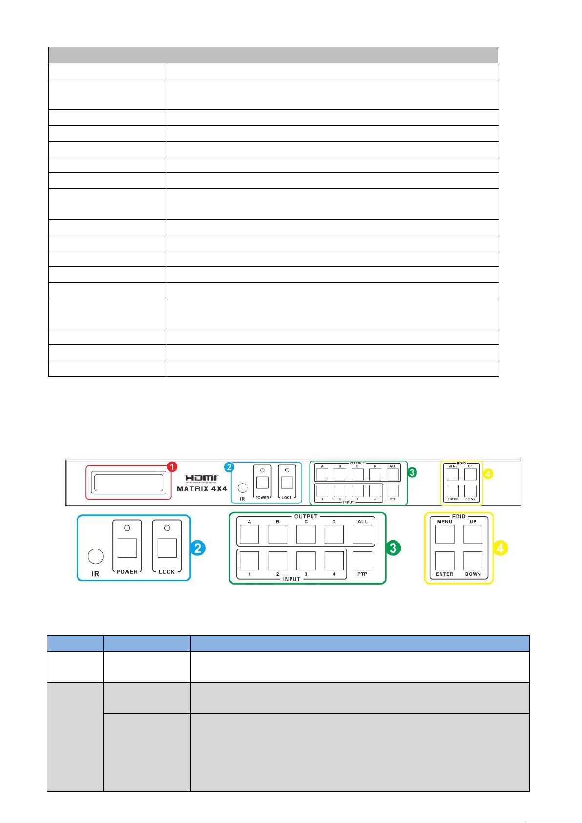
5. Panel Functions
5.1 Front Panel
Number
Name
Function description
1
LCM
Display the information of each input and output setting and EDID
management.
2
IR
IR Receiver window (accepts the remote control signal of this
device only).
POWER
Press this button to power the device on/off. The LED will illuminate
green when the power is on, red when it is in 'Standby' mode.

5
LOCK
Press this button to lock all the buttons on the panel, press again to
unlock
3
OUTPUT/INPUT
Press the OUTPUT and INPUT button to select the output
corresponding input.
For example: Press OUPUT ALL>INPUT 1, The OUTPUT A,B,C,D will
be set to INPUT 1.
Press PTP button, The OUTPUT A,B,C,D will corresponding INPUT
1,2,3,4.
4
EDID
Smart EDID management, the LCM will display the EDID operation.
Press the MENU button will enter the EDID management window,
Press UP or DOWN button to select the needed EDID setting,
Press ENTER button to select the download input source.
It can easy download any EDID mode to any input source.
Note: The EDID mode table
EDID Mode
EDID Description
1
1080p, 2CH AUDIO
2
1080p, DOLBY/DTS 5.1
3
1080p, HD AUDIO
4
1080i, 2CH AUDIO
5
1080i, DOLBY/DTS 5.1
6
1080i, HD AUDIO
7
3D,1080p, 2CH AUDIO
8
3D, 1080p,DOLBY/DTS 5.1
9
3D,1080p, HD AUDIO
10
4K x 2K@30Hz, 2CH AUDIO
11
4K x 2K@30Hz , DOLBY/DTS 5.1
12
4K x 2K@30Hz , HD AUDIO
13
4K x 2K@60Hz, 2CH AUDIO
14
4K x 2K@60Hz , DOLBY/DTS 5.1
15
4K x 2K@60Hz , HD AUDIO
16
Copy from HDMI OUTPUT A
17
Copy from HDMI OUTPUT B
18
Copy from HDMI OUTPUT C
19
Copy from HDMI OUTPUT D
20
Copy from HDBT OUTPUT A
21
Copy from HDBT OUTPUT B
22
Copy from HDBT OUTPUT C
23
Copy from HDBT OUTPUT D
EDID. What is it and what is it used for?
Under normal circumstances, a source device (digital and analog) will require information about a connected
device/display to assess what resolutions and features are available. The source can then cater its output to send
only resolutions and features that are compatible with the attached device/display. This information is called EDID
(Extended Display Information Data) and a source device can only accept and read one EDID from a connected
device/display. Likewise, the source an only output one resolution for use by a connected device/display.

6
Why is EDID so important with the HDMI Matrix?
The Matrix is complex piece of technology that replicates and switches between multiple inputs and outputs. Each
connected source device will require one EDID to read. EDID management is carefully handled by HDMI Matrix to
provide a single EDID for each source to read.
What options do I have to manage the EDID in the HDMI Matrix?
First, it is important to note that each source device can only output one video/audio signal type. This includes
resolutions and timings. When multiple devices/displays are used, such as with the HDMI Matrix, it is important to
use devices/displays that have similar or compatible resolutions/features. This will ensure that the single
video/audio signal produced by the source device is accepted by all of the connected output devices/displays. The
user has the option, through the EDID management window, to choose how the unit will manage the EDID from
multiple HDMI devices/displays. Therefore the user has some control over the resolutions/features that the source
devices will output. The HDMI Matrix has a multiple EDID management modes that will control how the EDID
information from multiple devices/displays are combined, ignored, and routed.
5.2 Rear panel
Number
Name
Function description
1
GND
Connect the Housing to ground.
2
IR Matrix
IR EXT: if the panel sensor is obstructed or the unit is installed in a
closed area out of infrared line of sight, the IR RX receiver included can
be inserted into the HUB IR port at the rear to extend the IR sensor
range and enable local control of the matrix.
IR IN/OUT: Super IR control system interface. For further details,
please refer to the Super IR system control introduction.
3
PC CONTROL
TCP/IP: This port is the link for TCP/IP control, connect to an active
Ethernet link with an RJ45 terminated cable.
RS-232: Connect to a PC or control system with D-Sub 9-pin cable for
the transmission of RS-232 commands.
4
HDMI INPUT
Connect to the HDMI input source devices such as a DVD player or a
Set-top Box with HDMI cable.
5
HDMI OUTPUT
The HDMI OUTPUT connect to HDMI equipped TVs or monitors and
the HDBT OUTPUT connect to the HDBT Receiver. The coaxial and
analog audio output connect to the audio amplifier. The TX and RX for
RS-232 communication with the HDBT Receiver TX and RX.
6
AC POWER
INPUT
Connect to AC power with AC power cable.

7
6. Remote Control
1. Press the button to power on the matrix or set it to standby mode.
2. Press the button to select output A for input 1,2,3 or 4 port.
Press this button to select the previous input port and to select the next
input port.
7. IR Control system(IR Call-back of Matrix and Source Devices)
The matrix is not only a switcher and extender of multiple HDMI signals to
multiple HDMI receivers located remotely, it also passes IR control signals
through the IR call-back system to the matrix and HDMI sources for full,
independent control of all connected inputs from output locations.
Two-way IR Call-back between matrix, Sources and Displays from Multiple
Locations
A key feature on the matrix is discrete IR control of the matrix, sources and
displays from any location –so inputs at the matrix end can be controlled at a
display location and displays can be controlled at the matrix location. This is
accomplished by placing a series of IR Emitters on devices to control and IR
Receivers at all locations you wish to control from to enable the IR signal to
travel both ways via the single Cat5e/6/7 cable.
01. At Matrix end: Insert the 3.5mm jacks of the IR TX Emitters included with the unit into the IR TX Emitter ports
at the rear of the matrix according to input. The IR signal is added to the HDMI of the input device, for example, if
the user is watching Blue-ray on input 1, the IR signal will be directed through the IR TX1 socket to control the
device.
As each IR TX port is allocated to an individual HDMI input port, if the user is unable to establish IR control of the
device, care should be taken to check firstly, that the IR emitter and HDMI input ports match (Input 1-TX1,
Input2-TX2 etc.) with plugs secured in correct ports, and secondly, that the IR TX emitter sensors are firmly
8
attached directly to the front of inputs and covering infrared sensor windows of the source devices. Some later
adjustment may be needed to the location of the sensor to achieve the best performance results - sometimes
moving the sensor to different areas on the source can improve IR performance.
NOTE: Infrared receiving areas of devices can be located by shining a flashlight onto the front of the device –the
sensor should be able to be seen through the plastic as a small, round object inside. Insert 3.5mm jacks of IR RX
receivers into RX ports, making sure the receivers themselves are placed in clear view to receive an infrared signal
from the remote handset used to control the display outputs.
02. At display end: Insert the IR RX Receiver jack into the IR RX port of the display receiver balun, with the receivers
themselves placed in clear view on or near the displays to receive an infrared signal from the remote handset used
to control inputs. Insert the IR TX Emitter jack into the IR TX port of the display receiver balun, ensuring that the
emitter sensor is securely attached to infrared sensor window of the display. Follow the same connection and
positioning for all baluns/displays connected to the matrix. If all IR TX Emitters and IR RX Receivers are positioned
and connected correctly with sources, displays and display receivers fully powered and the matrix set to IR
call-back enabled and IR TX Switch mode activated, two-way IR will now be possible.
Note: Misplaced or poorly secured IR Emitters and Receivers may result in intermittent IR control signals passed to
and from the matrix. Check your placement and adjust if necessary.
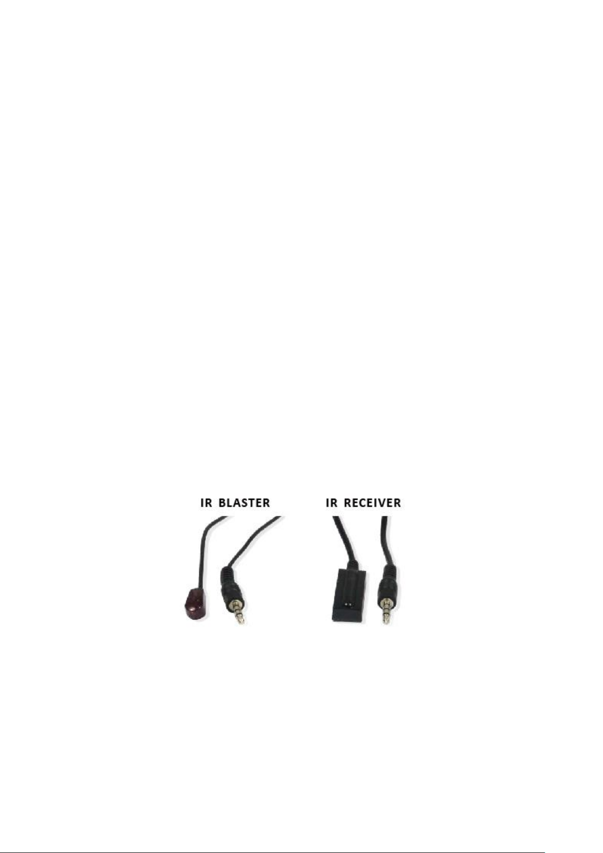
IR BLASTER (TX)
To control the source: Plug IR Blaster into IR OUT port of transmitter unit; place blaster in front of the IR eye of the
source.
To control the display: Plug IR Blaster into IR OUT port of receiver unit; place blaster in front of the IR eye of the
display.
IR RECEIVER (RX)
To control the source: Plug IR Receiver into IR IN port of receiver unit; place receiver at or near display.
To control the display: Plug IR Receiver into IR IN port of transmitter unit; place receiver in position where it is able
to receive remote signals.
9
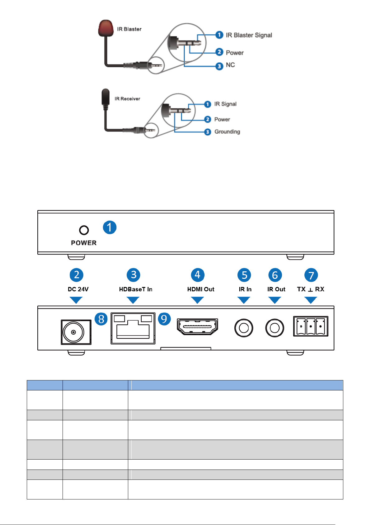
8. HDBT Receiver
Number
Name
Function description
1
POWER
This LED illuminates when the device is connected with power
supply
2
DC 24V
Plug the 24V DC power supply into the unit.
3
HDBaseT In
Standard HD BaseT signal input port. Connect HD BaseT transmitter
with a UTP cable.
4
HDMI Out
HDMI output port. This slot is where you connect the HDTV or
monitor with HDMI cable.
5
IR In
Channel 1 IR Receiver. Connect with Wideband IR Rx.
6
IR Out
Channel 2 IR Transmitter. Connect with Wideband IR Tx.
7
RS-232
Phoenix jack provide Serial port control signal from receiver or to
receiver.

10
8
Connection Signal
Indicator Lamp
※Illuminate: The Transmitter and Receiver are in good connection
status.
※Flashing: The Transmitter and Receiver are in poor connection
status.
※Dark: The Transmitter and Receiver are not connected.
9
Data Signal
Indicator Lamp
※Illuminate: The HDMI signal with HDCP.
※Flashing: The HDMI signal without HDCP.
※Dark: No HDMI signal.
※Description 1 POE(Power Over Ethernet) Application Example
This system can run by only the matrix(TX) is powered, RXs do not need powered.
11
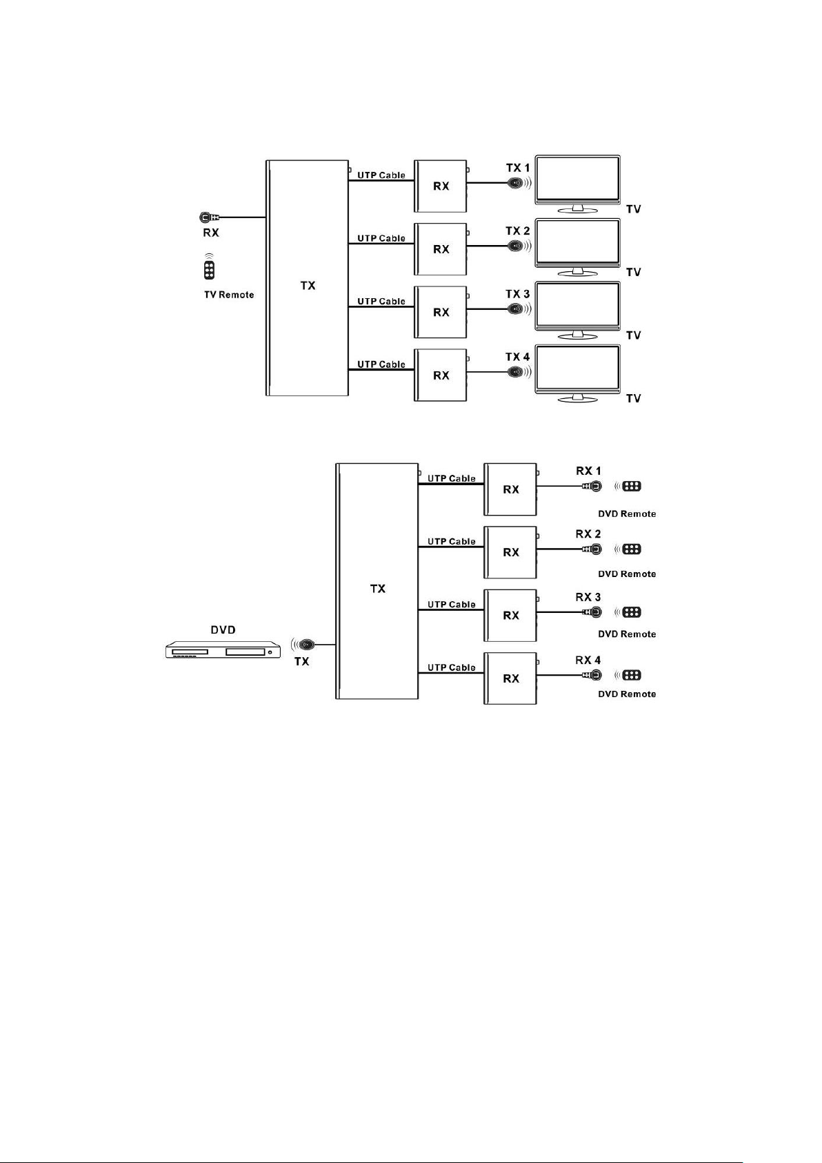
※Description 2 GLOBAL IR control Application Example
TV remote can control all TV at the same time.
All DVD remotes can control DVD, but not at the same time.
12
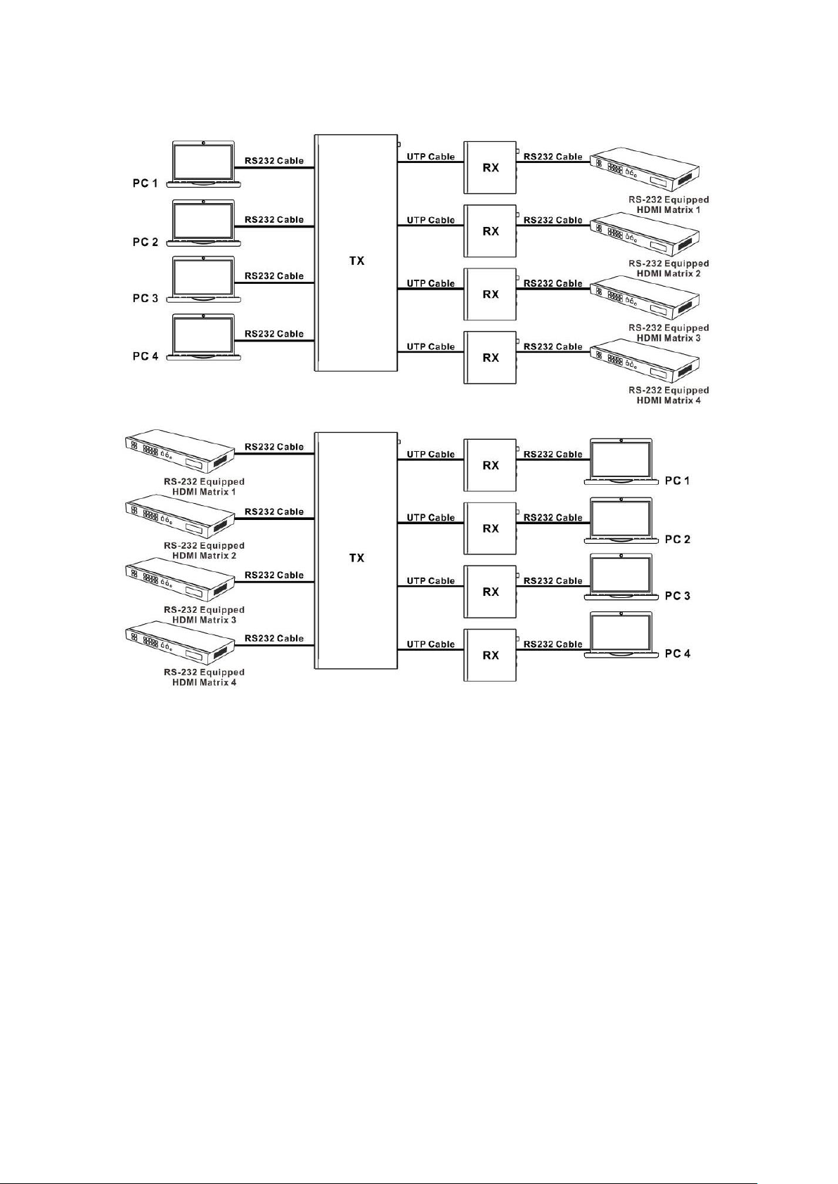
※Description 3 Bidirectional RS-232 control Application Example
This system provides 4 channel RS-232.
13
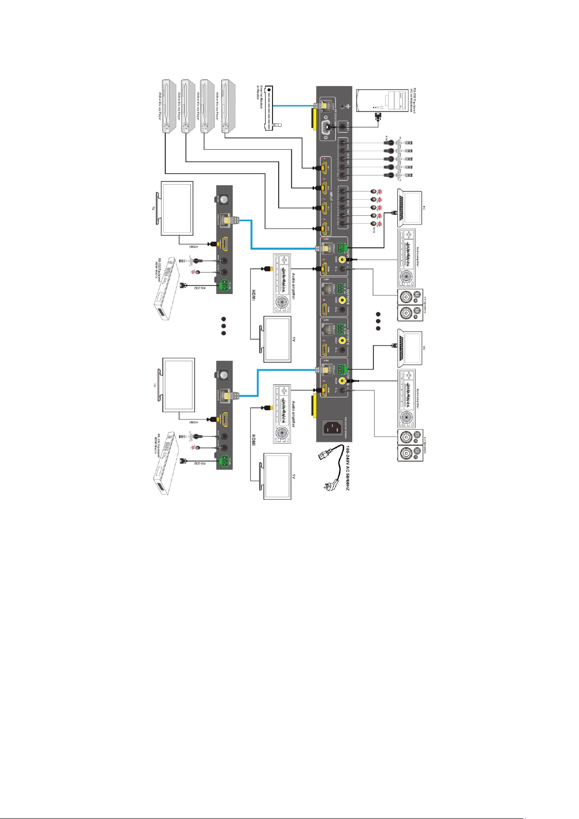
9. Operate and Connect
1. Connect up to 4 sources such as a Blue-Ray Player, game console, A/V Receiver, Cable or Satellite Receiver,
etc. to the HDMI inputs on the unit. Do not hot plug! Insert and extract cables carefully with the power
switch off. Connecting and disconnecting while the unit is powered can result in damage to circuitry.
2. Connect the output HDBT ports and/or HDMI output ports, starting with output 1, to the HDBT Receiver
display receivers (sold separately) (using well terminated or pre-terminated Cat5e/6/7 cables no longer than
230 ft/70M)
3. If utilizing UTP, connect the output HDMI ports of the HDBT Receiver display receivers (sold separately) to
high-definition displays such as an HDTV or HD projector that use HDMI inputs. Note that high-speed HDMI
cables are recommended for the distances that are required for each connection.
4. Plug in IR transmitters to the back of the Matrix Selector Switcher unit (IR TX), the transmitters are labeled IR
TX, place in front of the IR receiver of the source, ensure that each emitter is placed in front of the IR receiver
eye. Double-sided adhesive tape provided.
5. Plug in IR receivers to the port of the HDBT Receiver display receivers (sold separately) ,the receivers are
labeled IR RX, use provided double-sided adhesive tape to stick emitters at each display at a desired place
that will receive a remote signal.
6. For power, plug in the source first, followed by the Matrix (power supply included), followed by the display
receivers, followed by each output connected.
7. Power on each device in the same sequence.
Table of contents
Other HDCVT TECHNOLOGY Matrix Switcher manuals


