manuals.online logo
Brands
  1. Home
  2. •
  3. Brands
  4. •
  5. HEALTH RIDER
  6. •
  7. Treadmill
  8. •
  9. HEALTH RIDER Softstrider 225p Treadmill User manual

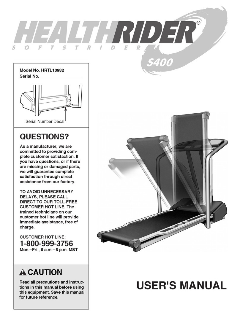
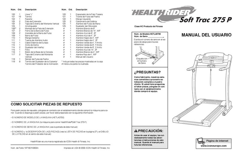
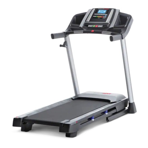
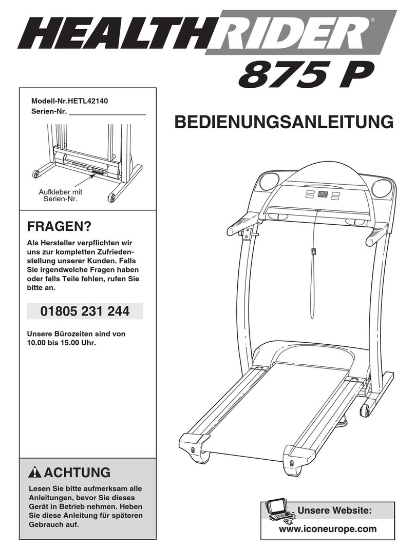
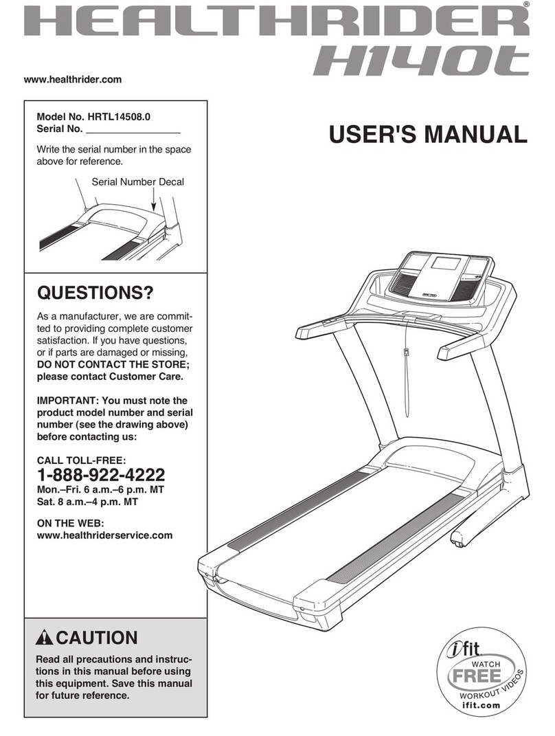
HEALTH RIDER Softstrider 225p Treadmill User manual

Serial Number
Decal
USER'S MANUAL
Model No. HETL40530
Serial No.
CAUTION
Read all precautio s a d i struc-
tio s i this ma ual before usi g
this equipme t. Save this ma ual
for future refere ce.
www.ico europe.com
Visit our website at
QUESTIONS?
As a ma ufacturer, we are com-
mitted to providi g complete
customer satisfactio . If you
have questio s, or if there are
missi g or damaged parts,
please call:
Or write:
ICON Health & Fit ess, Ltd.
Customer Service Departme t
U it 4
Revie Road I dustrial Estate
Revie Road, Beesto
Leeds, LS118JG
UK
email: csuk@ico europe.com
08457 089 009
TABLE OF CONTENTS
IMPORTANT PRECAUTIONS . . . . . . . . . . . . . . . . . . . . . . . . . . . . . . . . . . . . . . . . . . . . . . . . . . . . . . . . . . . . . . . . .3
BEFORE YOU BEGIN . . . . . . . . . . . . . . . . . . . . . . . . . . . . . . . . . . . . . . . . . . . . . . . . . . . . . . . . . . . . . . . . . . . . . . .5
ASSEMBLY . . . . . . . . . . . . . . . . . . . . . . . . . . . . . . . . . . . . . . . . . . . . . . . . . . . . . . . . . . . . . . . . . . . . . . . . . . . . . . .
OPERATION AND ADJUSTMENT . . . . . . . . . . . . . . . . . . . . . . . . . . . . . . . . . . . . . . . . . . . . . . . . . . . . . . . . . . . . .9
HOW TO FOLD AND MOVE THE TREADMILL . . . . . . . . . . . . . . . . . . . . . . . . . . . . . . . . . . . . . . . . . . . . . . . . . .13
TROUBLESHOOTING . . . . . . . . . . . . . . . . . . . . . . . . . . . . . . . . . . . . . . . . . . . . . . . . . . . . . . . . . . . . . . . . . . . . . .15
CONDITIONING GUIDELINES . . . . . . . . . . . . . . . . . . . . . . . . . . . . . . . . . . . . . . . . . . . . . . . . . . . . . . . . . . . . . . .17
ORDERING REPLACEMENT PARTS . . . . . . . . . . . . . . . . . . . . . . . . . . . . . . . . . . . . . . . . . . . . . . . . . .Back Cover
Note: An EXPLODED DRAWING and a PART LIST are attached in the centre of this manual.
2
HealthRider is registered trademark of ICON Health & Fitness, Inc.
1. It is the respo sibility of the ow er to e sure
that all users of this treadmill are adequately
i formed of all war i gs a d precautio s.
2. Use the treadmill o ly as described i this
ma ual.
3. Place the treadmill o a level surface, with at
least 2 m (8 ft.) of cleara ce behi d it a d 0.5
m (2 ft.) o each side. Do ot place the tread-
mill o a y surface that blocks air ope i gs.
To protect the floor or carpet from damage,
place a mat u der the treadmill.
4. Keep the treadmill i doors, away from mois-
ture a d dust. Do ot put the treadmill i a
garage or covered patio, or ear water.
5. Do ot operate the treadmill where aerosol
products are used or where oxyge is bei g
admi istered.
6. Keep childre u der the age of 12 a d pets
away from the treadmill at all times.
7. The treadmill should be used o ly by perso s
weighi g 115 kg (250 lbs.) or less.
8. Never allow more tha o e perso o the
treadmill at a time.
9. Wear appropriate exercise clothes whe
usi g the treadmill. Do ot wear loose clothes
that could become caught i the treadmill.
Athletic support clothes are recomme ded for
both me a d wome . Always wear athletic
shoes. Never use the treadmill with bare feet,
wearing only stockings, or in sandals.
10. Whe co ecti g the power cord (see page 9),
plug the power cord i to a earthed circuit. No
other applia ce should be o the same circuit.
Whe replaci g the fuse, a ASTA approved
BS1362 type should be fitted to the fuse car-
rier. A 13 amp fuse should be used.
11. If a exte sio cord is eeded, use o ly a 3-
co ductor, 1 mm2(14-gauge) cord that is o
lo ger tha 1.5 m (5 ft.).
12. Keep the power cord away from heated
surfaces.
13. Never move the walki g belt whilst the power
is tur ed off. Do ot operate the treadmill if
the power cord or plug is damaged, or if the
treadmill is ot worki g properly. (See BE-
FORE YOU BEGIN o page 5 if the treadmill is
ot worki g properly.)
14. Never start the treadmill whilst you are sta d-
i g o the walki g belt. Always hold the
ha drails whilst usi g the treadmill.
15. The treadmill is capable of high speeds.
Adjust the speed i small i creme ts to avoid
sudde jumps i speed.
16. The pulse se sor is ot a medical device.
Various factors, i cludi g the user's move-
me t, may affect the accuracy of heart rate
readi gs. The pulse se sor is i te ded o ly
as a exercise aid i determi i g heart rate
tre ds i ge eral.
17. Never leave the treadmill u atte ded whilst it is
ru i g. Always remove the key a d u plug
the power cord whe the treadmill is ot i use.
18. Do ot attempt to raise, lower, or move the
treadmill u til it is properly assembled. (See
ASSEMBLY o page 6, a d HOW TO FOLD
AND MOVE THE TREADMILL o page 13.)
You must be able to safely lift 20 kg (45 lbs.) to
raise, lower, or move the treadmill.
19. Whe foldi g or movi g the treadmill, make
sure that the storage latch is fully closed.
20. I spect a d properly tighte all parts of the
treadmill regularly.
WARNING:To reduce the risk of bur s, fire, electric shock, or i jury to perso s, read the
followi g importa t precautio s a d i formatio before operati g the treadmill.
IMPORTANT PRECAUTIONS
4
The decals show has bee placed o your treadmill. If the
decal is missi g, or if it is ot legible, please call our Customer
Service Departme t to order a free replaceme t decal (see
ORDERING REPLACEMENT PARTS o the back cover of this
ma ual). Apply the decal i the locatio show .
Note: The decal is shown at 38% of actual size.
21. Never i sert a y object i to a y ope i g.
22. DANGER:Always u plug the power
cord immediately after use, before clea i g
the treadmill, a d before performi g the
mai te a ce a d adjustme t procedures de-
scribed i this ma ual. Never remove the
motor hood u less i structed to do so by a
authorised service represe tative. Servici g
other tha the procedures i this ma ual
should be performed by a authorised ser-
vice represe tative o ly.
23. This treadmill is i te ded for i -home use
o ly. Do ot use this treadmill i a commer-
cial, re tal, or i stitutio al setti g.
WARNING:Before begi i g this or a y exercise program, co sult your physicia . This
is especially importa t for perso s over the age of 35 or perso s with pre-existi g health problems.
Read all i structio s before usi g. ICON assumes o respo sibility for perso al i jury or property
damage sustai ed by or through the use of this product.
SAVE THESE INSTRUCTIONS
Congratulations for selecting the new HealthRider®
SoftTrac 225P treadmill. The 225P treadmill combines
advanced technology with innovative design to help
you get the most from your exercise in the conve-
nience and privacy of your home. And when you’re not
exercising, the unique 225P can be folded up, requiring
less than half the floor space of other treadmills.
For your be efit, read this ma ual carefully before
usi g the treadmill. If you have additional questions,
please call our Customer Service Department at 08457
089 009. To help us assist you, please note the prod-
uct model number and serial number before calling.
The model number of the treadmill is HETL40530. The
serial number can be found on a decal attached to the
treadmill (see the front cover of this manual for the lo-
cation).
Before reading further, please familiarise yourself with
the parts that are labelled in the drawing below.
BEFORE YOU BEGIN
Handrail
Upright
Storage Latch
Key/Clip
Circuit Breaker
Walking Belt
Cushioned Walking Platform
for maximum exercise comfort
Foot Rail
BACK
RIGHT SIDE
Rear Roller
Adjustment Bolts
Console Water Bottle Holder
(Bottle not included)
Incline Leg
6
1. With the help of a second person, carefully raise the
Uprights (11) until the treadmill is in the position shown.
Insert one of the Extension Legs (34) into the treadmill
as shown. (Note: It may be helpful to tip the Uprights [11]
in the direction shown by the arrow as you insert the
Extension Leg.) Make sure that the Base Pad (40) is un-
derneath the Extension Leg. Attach the Extension Leg
with an Extension Leg Screw (108); push o the head
of the Exte sio Leg Screw whilst tighte i g it.
Attach the other Extension Leg (34) in the same way.
Extension Leg Screw (108)–2 Long Screw (3)–
Handrail Screw (53)–2
11
1
ASSEMBLY
Assembly requires two people. Set the treadmill in a cleared area and remove all packing materials. Do not
dispose of the packing materials until assembly is completed. Assembly requires the i cluded alle wre ch
a d your ow phillips screwdriver a d wire cutters .
Note: The underside of the treadmill walking belt is coated with high-performance lubricant. During shipping, a
small amount of lubricant may be transferred to the top of the walking belt or the shipping carton. This is a normal
condition and does not affect treadmill performance. If there is lubricant on top of the walking belt, simply wipe off
the lubricant with a soft cloth and a mild, non-abrasive cleaner.
34
108
11
40
WARNING: Do ot plug i the power
cord u til the treadmill is completely assembled.
2. Insert a Handrail (1) into the tube at the upper end of the
right Upright (11). Have a second person hold the
Handrail whilst you complete step 3.
11
1
2
3
14
11
1
5
3. Align the hole in the Handrail (1) with the indicated hole
in the right Upright (11). Thread a Handrail Screw (53)
two tur s into the Upright and the Handrail at the angle
shown in drawing 3b. It may be helpful to lift up and push
down on the Handrail as you thread the Handrail Screw.
4. Refer to drawing 4a. Slide a Handrail Endcap (41) onto
the end of the Handrail (1). The Handrail Endcap should
fit on the Handrail as shown, with the narrow part of the
Handrail Endcap on top. Pivot the lower end of the
Handrail to the side as shown. Refer to drawing 4b. Fold
the flap on the Handrail Endcap to one side or the other
as you position the Handrail Endcap on the Upright (11)
as shown in drawing 4c.
5. Refer to step 3. Tighten the Handrail Screw (53).
Attach the other Handrail (1) to the left Upright (11) as
described in steps 2 to 4.
Attach the Storage Latch (14) to the left Upright (11) with
two Long Screws (3). Be careful ot to overtighte the
Lo g Screws.
1
53
53
11
3a
Bottom View
4a 4b 4c
141
11
11
Narrow Part Flap
3b
. Refer to drawing a. Insert the included plastic tie (A)
through the indicated hole in the right Upright (11).
Refer to drawing b. Look into the right Upright (11) and
make sure the Wires (21) have been secured to the side
shown. Tighten the plastic tie (A).
11
a
A
21
A
11
b
8
7. Place the Console Base (4 ) on the Handrails (1) (only
the Right Handrail is shown). Pull out just enough of the
two Wires (21) to connect them to the receptacles in the
Console Base. Make a loop with the indicated plastic tie
and insert the two Wires through the loop. Locate the
Wire that has a two-pin connector and a three-pin con-
nector on the end. Plug the connectors into the matching
receptacles in the Console Base. If the co ectors do
ot fit easily, rotate them a d the plug them i . Slide
the Wire Cover ( ) onto the connectors so that they are
completely covered. Next, plug the other Wire into the
matching receptacle on the Console Base. WARNING:
Do ot co ect or disco ect the Wires whilst the
treadmill power cord is plugged i . Tighten the plastic
tie and cut off the end.
See the inset drawing. Loop one of the included plastic
ties around the Wire Cover ( ) so that the plastic tie is in
the two notches in the Wire Cover. Tighten the plastic tie
and cut off the end.
8. Thread four Long Screws (3) into the Handrails (1) and the
Console Base (4 ). Make sure that the wires i the Right
Ha drail are clear of the screw holes. After all four Long
Screws have been started, tighte them u til they are
s ug; do ot overtighte them.
The co sole requires three 1.5 V batteries. Alkaline bat-
teries are recommended. To install batteries, first touch
the Uprights (11) to discharge a y static. Next, open the
Battery Cover (4) as shown. Insert three batteries into the
battery compartment, maki g sure that the egative (–)
e ds of the batteries are touchi g the spri gs i the
battery compartme t. Close the Battery Cover, push up
on the tab, and then push the tab forward as shown in the
inset drawing. Make sure that the tab locks into place.
Remove the plastic ties used in step .
9. Make sure that all parts are properly tighte ed before you use the treadmill. Keep the included allen
wrench in a secure place. The allen wrench is used to adjust the walking belt (see page 1 ). To protect the
floor or carpet, place a mat under the treadmill.
4
33
1
Tab
Batteries
8
4
1
4
4
7
Tie
Tie
21
OPERATION AND ADJUSTMENT
THE PERFORMANT LUBETM WALKING BELT
Your treadmill features a walking belt coated with PERFORMANT LUBETM, a high-performance lubricant. IMPOR-
TANT: Never apply silico e spray or other substa ces to the walki g belt or the walki g platform. Such
substa ces will deteriorate the walki g belt a d cause excessive wear.
HOW TO PLUG IN THE POWER CORD
This product must be earthed. If it should malfunction or break
down, earthing provides a path of least resistance for electric
current to reduce the risk of electric shock. This product is equipped
with a cord having an equipment-earthing conductor and an earth-
ing plug.
Two power cords are i cluded. Select the o e that will fit your
outlet. Refer to drawi g 1. Plug the i dicated e d of the power
cord i to the socket o the treadmill. Next, lift the tab o the
ferrite box a d clamp the ferrite box arou d the power cord.
The ferrite box should ot be allowed to slide alo g the power
cord. Faste the i cluded plastic tie just behi d the ferrite box
a d cut off the excess plastic tie. Refer to drawi g 2. Plug the
power cord i to a appropriate outlet that is properly i stalled
a d earthed i accorda ce with all local codes a d ordi a ces.
Importa t: The treadmill is ot compatible with GFCI-equipped
outlets.
If the power cord is damaged, it must be replaced with a manufac-
turer-recommended power cord.
DANGER:Improper co ectio of the equipme t-earthi g co ductor ca result i a i -
creased risk of electric shock. Check with a qualified electricia or servicema if you are i doubt as
to whether the product is properly earthed. Do ot modify the plug provided with the product—if it
will ot fit the outlet, have a proper outlet i stalled by a qualified electricia .
1
2
Socket on treadmill
Outlet
Tab
Ferrite Box
Plastic
Tie
10
HOW TO PUT ON THE CHEST PULSE SENSOR
The chest pulse sensor consists of two components:
the chest strap and the sensor unit (see the drawing
below). Insert the tab on one end of the chest strap into
one end of the sensor unit, as shown in the inset draw-
ing. Press the end of the sensor unit under the buckle
on the chest strap. The tab should be flush with the
front of the sensor unit.
Next, wrap the
chest pulse sen-
sor around your
chest and attach
the other end of
the chest strap to
the sensor unit.
Adjust the length
of the chest strap,
if necessary. The
chest pulse sen-
sor should be under your clothes, tight against your
skin, and as high under the pectoral muscles or
breasts as is comfortable. Make sure that the logo on
the sensor unit is facing forward and is right-side-up.
Pull the sensor unit away from your body a few inches
and locate the two electrode areas on the inner side
(the electrode areas are covered by shallow ridges).
Using saline solution such as saliva or contact lens so-
lution, wet both electrode areas. Return the sensor unit
to a position against your chest.
CHEST PULSE SENSOR CARE AND MAINTENANCE
• Thoroughly dry the chest pulse sensor after each
use. The chest pulse sensor is activated when the
electrode areas are wetted and the heart rate
monitor is put on; the chest pulse sensor shuts off
when it is removed and the electrode areas are
dried. If the chest pulse sensor is not dried after
each use, it may remain activated longer than nec-
essary, draining the battery prematurely.
• Store the chest pulse sensor in a warm, dry place.
Do not store the chest pulse sensor in a plastic bag
or other container that may trap moisture.
• Do not expose the chest pulse sensor to direct
sunlight for extended periods of time; do not expose
it to temperatures above 50° C (122° F) or below
-10° C (14° F).
• Do not excessively bend or stretch the sensor unit
when using or storing the chest pulse sensor.
• Clean the sensor unit using a damp cloth—never
use alcohol, abrasives, or chemicals. The chest
strap may be hand washed and air dried.
CHEST PULSE SENSOR TROUBLESHOOTING
The i structio s o the followi g pages explai
how the chest pulse se sor is used with the co -
sole. If the chest pulse se sor does ot fu ctio
properly, try the steps below.
• Make sure that you are wearing the chest pulse sen-
sor as described at the left. Note: If the chest pulse
sensor does not function when positioned as de-
scribed, move it slightly lower or higher.
• Use saline solution such as saliva or contact lens
solution to wet the two electrode areas on the
sensor unit. If heart rate readings do not appear until
you begin perspiring, re-wet the electrode areas.
• As you walk or run on the treadmill, position your-
self near the centre of the walking belt. For the
co sole to display heart rate readi gs, the user
must be withi arm’s le gth of the co sole.
• The chest pulse sensor is designed to work with
people who have normal heart rhythms. Heart rate
reading problems may be caused by medical
conditions such as premature ventricular contrac-
tions (pvcs), tachycardia bursts, and arrhythmia.
• The operation of the chest pulse sensor can be
affected by magnetic interference caused by high
power lines or other sources. If it is suspected that
this is a problem, try relocating the treadmill.
• The CR2032 battery may need to be replaced (see
page 1 ).
Chest Strap
Tabs
Sensor Unit
Tab
Sensor
Unit Buckle
STEP-BY-STEP CONSOLE OPERATION
Make sure that the power
cord is properly plugged
in (see page 9). Next,
step onto the foot rails of
the treadmill. Find the
clip attached to the key,
and slide the clip onto
the waistband of your clothes. Insert the key into the
console. Test the clip by carefully taki g a few
steps backward u til the key is pulled from the
co sole. If the key is ot pulled from the co sole,
adjust the positio of the clip as eeded.
Note: The console can display distance and speed in
either kilometres or miles. (See HOW TO SELECT
KILOMETRES AND MILES on page 12.)
I sert the key fully i to the co sole.
Inserting the key will
not turn on the dis-
plays. The displays
will turn on when the
On/Reset button is
pressed or when the
walking belt is started.
Note: If you just in-
stalled batteries, the displays will already be on.
Reset the speed co trol a d start the walki g
belt.
Slide the speed control
down to the Reset position.
Note: Each time the walk-
i g belt is stopped, the
speed co trol must be
moved to the Reset posi-
tio before the walki g
belt ca be restarted.
After you have moved the speed control to the
Reset position, slowly slide the speed control up-
ward until the walking belt begins to move at slow
speed. Carefully step onto the walking belt and
begin exercising. Change the speed of the walking
belt as desired by sliding the speed control.
To stop the walking belt, step onto the foot rails
and slide the speed control to the Reset position.
During the first few minutes that you use the tread-
mill, inspect the alignment of the walking belt, and
align it if necessary (see page 1 ).
2
1
CAUTION:Before operati g the
co sole, read the followi g precautio s.
• Do ot sta d o the walki g belt whe tur -
i g o the power.
• Always wear the clip (see the drawi g
above) whilst usi g the treadmill. Whe the
key is removed, the walki g belt will stop.
• Adjust the speed i small i creme ts.
• To reduce the possibility of electric shock,
keep the co sole dry. Avoid spilli g liquids
o it a d use o ly a sealable water bottle.
On/Reset
Button
If there is a thin sheet of
clear plastic on the console,
remove it.
Clip
Key
Adjust the i cli e of the treadmill as desired.
To change the incline of the
treadmill, press the top or bot-
tom of the incline control until
the desired incline level is
reached.
Follow your progress with the four displays.
Speed display—This
display shows the speed
of the walking belt.
Time display—This
display shows the
elapsed time.
Dista ce display—
This display shows the
distance that you have
walked or run.
Cals/Fat Cals/Pulse
display—This display
shows the approximate
numbers of calories and
fat calories you have
burned. (See Fat
Burning on page 17.)
Every few seconds, the
display will change
from one number to the
other. Arrows in the
display will indicate
which number is cur-
rently shown. Note:
When the chest pulse sensor is worn, this display
will also show your heart rate.
To reset the displays at any time, press the
On/Reset button.
Whe you are fi ished exercisi g, stop the
walki g belt a d remove the key.
Step onto the foot rails, stop the walking belt, and
remove the key from the console. The displays will
turn off a few minutes after the key is removed.
Note: To co serve the batteries, the displays
will automatically tur off a y time that the
walki g belt is stopped a d the O /Reset but-
to is ot pressed for a few mi utes.
HOW TO SELECT KILOMETRES AND MILES
The console can display distance and speed in either
kilometres or miles. To change the unit of measure-
ment, first UNPLUG THE POWER CORD. Next, re-
move the screws attaching the console to the console
base. Lift the console a few inches, being careful not to
pull on the wires, and turn the console over. Locate the
small switch on the back of the console. Move the
switch up or down to select kilometres or miles.
Reattach the console to the console base. Next, re-
move o e of the batteries from the co sole for
about five seco ds a d the rei sert it. This will
reset the co sole.
5
4
3
Screws
Console
Screws
Switch
Arrow
12
HOW TO FOLD AND MOVE THE TREADMILL
HOW TO FOLD THE TREADMILL FOR STORAGE
Before folding the treadmill, unplug the power cord.
CAUTION: You must be able to safely lift 20 kg (45 lbs.)
to raise, lower, or move the treadmill.
1. Hold the treadmill with your hands in the locations shown
at the right. To decrease the possibility of i jury, be d
your legs a d keep your back straight. As you raise
the treadmill, make sure to lift with your legs rather
tha your back. Raise the treadmill about halfway to the
vertical position.
2. Move your right hand to the position shown and hold the
treadmill firmly. Raise the treadmill until the storage latch
closes over the catch. It may be helpful to push out on
the handrail as you raise the treadmill. Make sure that
the storage latch is fully e gaged over the catch.
To protect the floor or carpet from damage, place a
mat u der the treadmill. Keep the treadmill out of
direct su light. Do ot leave the treadmill i the stor-
age positio i temperatures above 30° C (85° F).
HOW TO MOVE THE TREADMILL
Before moving the treadmill, convert the treadmill to the stor-
age position as described above. Make sure that the stor-
age latch is fully e gaged over the catch.
1. Hold the upper ends of the handrails. Place one foot on
the base as shown.
2. Tilt the treadmill back until it rolls freely on the front
wheels. Carefully move the treadmill to the desired loca-
tion. To reduce the risk of i jury, use extreme cautio
whilst movi g the treadmill. Do ot move the tread-
mill over a u eve surface.
3. Place one foot on the base, and carefully lower the tread-
mill until it is resting in the storage position. Base
Front Wheels
Engaged
13
Storage
Latch
Catch
HOW TO LOWER THE TREADMILL FOR USE
1. Hold the upper end of the treadmill with your right hand
as shown. Using your left thumb, press the storage latch
and hold it. Pivot the treadmill until the frame and foot rail
are past the storage latch.
2. Hold the treadmill firmly with both hands, and lower the
treadmill to the floor. Do ot drop the treadmill frame to
the floor. CAUTION: To decrease the possibility of i -
jury, be d your legs a d keep your back straight.
Storage
Latch
Unlatched
14
TROUBLESHOOTING
Most treadmill problems ca be solved by followi g the steps below. Fi d the symptom that applies, a d
follow the steps listed. If further assista ce is eeded, please call our Customer Service Departme t.
PROBLEM: The power does ot tur o
SOLUTION: a. Make sure that the power cord is plugged into a properly earthed outlet (see page 9). If an extension
cord is needed, use only a 3-conductor, 1 mm2(14-gauge) cord that is no longer than 1.5 m (5 ft.).
b. After the power cord has been plugged in, make sure that the key is fully inserted into the console.
c. Check the circuit breaker located on the treadmill
near the power cord. If the switch protrudes as
shown, the circuit breaker has tripped. To reset the
circuit breaker, wait for five minutes and then press
the switch back in.
PROBLEM: The power tur s off duri g use
SOLUTION: a. Check the circuit breaker located on the treadmill frame near the power cord (see the drawing
above). If the circuit breaker has tripped, wait for five minutes and then press the switch back in.
b. Make sure that the power cord is plugged in. If the power cord is plugged in, unplug it, wait for
five minutes, and then plug it back in.
c. Remove the key from the console. Reinsert the key fully into the console.
d. If the treadmill still will not run, please call our Customer Service Department.
PROBLEM: The displays of the co sole do ot fu ctio properly
SOLUTION: a. UNPLUG THE POWER CORD. Check the batteries in the console. If the batteries need to be re-
placed, see assembly step 8 on page 8. Most problems are the result of drained batteries.
b. Remove the key from the console and UNPLUG THE POWER CORD. Remove the screws from
the hood. Carefully remove the hood.
Locate the Reed Switch (44) and the Magnet (45) on
the left side of the Pulley (50). Turn the Pulley until the
Magnet is aligned with the Reed Switch. Make sure
that the gap betwee the Mag et a d the Reed
Switch is about 3 mm (1/8 i .). If necessary, loosen
the Screw (33) and move the Reed Switch slightly.
Retighten the Screw. Re-attach the hood, and run the
treadmill for a few minutes to check for a correct
speed reading.
PROBLEM: The walki g belt slows whe walked o
SOLUTION: a. If an extension cord is needed, use only a 3-conductor, 1mm2(14-gauge) cord that is no longer
than 1.5 m (5 ft.).
Tripped Reset
c
45
44
33
Top
View
3mm 50
b
b. If the walking belt is overtightened, treadmill perfor-
mance may decrease and the walking belt may be-
come damaged. Remove the key and UNPLUG THE
POWER CORD. Using the allen wrench, turn both
rear roller adjustment bolts counterclockwise, 1/4 of a
turn. When the walking belt is properly tightened, you
should be able to lift each side of the walking belt 5 to
8 cm (2 to 3 in.) off the walking platform. Be careful to
keep the walking belt centred. Plug in the power cord,
insert the key and run the treadmill for a few minutes.
Repeat until the walking belt is properly tightened.
c. If the walking belt still slows when walked on, call our Customer Service Department.
PROBLEM: The walki g belt is off-ce tre or slips whe walked o
SOLUTION: a. If the walking belt is off-centre, first remove the key
and UNPLUG THE POWER CORD. If the walki g
belt has shifted to the left, use the allen wrench to
turn the left rear roller bolt clockwise 1/2 of a turn; if
the walki g belt has shifted to the right, turn the
bolt counterclockwise 1/2 of a turn. Be careful not to
overtighten the walking belt. Plug in the power cord,
insert the key and run the treadmill for a few minutes.
Repeat until the walking belt is centred.
b. If the walking belt slips when walked on, first remove
the key and UNPLUG THE POWER CORD. Using
the allen wrench, turn both rear roller bolts clockwise,
1/4 of a turn. When the walking belt is correctly tight-
ened, you should be able to lift each side of the walk-
ing belt 5 to 8 cm (2 to 3 in.) off the walking platform.
Be careful to keep the walking belt centred. Plug in
the power cord, insert the key and carefully walk on
the treadmill for a few minutes. Repeat until the walk-
ing belt is properly tightened.
PROBLEM: The heart rate mo itor does ot fu ctio properly
SOLUTION: a. If the heart rate monitor does not function properly, refer to CHEST PULSE SENSOR TROU-
BLESHOOTING on page 10.
b. If the heart rate monitor still does not function properly, the battery
should be replaced. To replace the battery, locate the battery cover
on the back of the sensor unit. Insert a coin into the slot in the cover
and turn the cover counterclockwise to the “open” position. Remove
the cover. Next, remove the old battery from the sensor unit. Insert
a new CR 2032 battery, making sure that the writing is on top.
Make sure that the rubber gasket is in place in the sensor unit.
Reattach the battery cover and turn it to the closed position.
Rear Roller Adjustment Bolts
5–8 cm
b
b
a
CR2032
Battery
Gasket
b
16
CONDITIONING GUIDELINES
The following guidelines will help you to plan your ex-
ercise program. For more detailed exercise informa-
tion, obtain a reputable book or consult your physician.
EXERCISE INTENSITY
Whether your goal is to burn fat or to strengthen your
cardiovascular system, the key to achieving the
desired results is to exercise with the proper intensity.
The proper intensity level can be found by using your
heart rate as a guide. The chart below shows recom-
mended heart rates for fat burning and aerobic exercise.
To find the proper heart rate for you, first find your age
near the bottom of the chart (ages are rounded off to
the nearest ten years). Next, find the three numbers
above your age. The three numbers define your “train-
ing zone.” The lower two numbers are recommended
heart rates for fat burning; the higher number is the
recommended heart rate for aerobic exercise.
To measure your heart rate during exercise, use the
chest pulse sensor.
Fat Bur i g
To burn fat effectively, you must exercise at a relatively
low intensity level for a sustained period of time.
During the first few minutes of exercise, your body
uses easily accessible carbohydrate calories for en-
ergy. Only after the first few minutes does your body
begin to use stored fat calories for energy. If your goal
is to burn fat, adjust the speed and incline of the tread-
mill until your heart rate is near the lowest number in
your training zone.
For maximum fat burning, adjust the speed and incline
of the treadmill until your heart rate is near the middle
number in your training zone.
Aerobic Exercise
If your goal is to strengthen your cardiovascular system,
your exercise must be “aerobic.” Aerobic exercise is ac-
tivity that requires large amounts of oxygen for pro-
longed periods of time. This increases the demand on
the heart to pump blood to the muscles, and on the
lungs to oxygenate the blood. For aerobic exercise, ad-
just the speed and incline of the treadmill until your heart
rate is near the highest number in your training zone.
WORKOUT GUIDELINES
Each workout should include the following three parts:
A Warm-up—Start each workout with 5 to 10 minutes
of stretching and light exercise. A proper warm-up in-
creases your body temperature, heart rate and circula-
tion in preparation for exercise.
Trai i g Zo e Exercise—After warming up, increase
the intensity of your exercise until your pulse is in your
training zone for 20 to 0 minutes. (During the first few
weeks of your exercise program, do not keep your
pulse in your training zone for longer than 20 minutes.)
Breathe regularly and deeply as you exercise—never
hold your breath.
A Cool-dow —Finish each workout with 5 to 10 min-
utes of stretching to cool down. This will increase the
flexibility of your muscles and will help prevent post-ex-
ercise problems.
EXERCISE FREQUENCY
To maintain or improve your condition, complete three
workouts each week, with at least one day of rest be-
tween workouts. After a few months, you may com-
plete up to five workouts each week if desired. The key
to success is to make exercise a regular and enjoyable
part of your everyday life.
WARNING:Before begi i g this
or a y exercise program, co sult your physi-
cia . This is especially importa t for i dividu-
als over the age of 35 or i dividuals with pre-
existi g health problems.
The pulse se sor is ot a medical device.
Various factors, i cludi g your moveme t,
may affect the accuracy of heart rate readi gs.
The se sor is i te ded o ly as a exercise aid
i determi i g heart rate tre ds i ge eral.
SUGGESTED STRETCHES
The correct form for several basic stretches is shown at the right.
Move slowly as you stretch—never bounce.
1. Toe Touch Stretch
Stand with your knees bent slightly and slowly bend forward from
your hips. Allow your back and shoulders to relax as you reach
down toward your toes as far as possible. Hold for 15 counts, then
relax. Repeat 3 times. Stretches: Hamstrings, back of knees, and
back.
2. Hamstri g Stretch
Sit with one leg extended. Bring the sole of the opposite foot to-
ward you and rest it against the inner thigh of your extended leg.
Reach toward your toes as far as possible. Hold for 15 counts,
then relax. Repeat 3 times for each leg. Stretches: Hamstrings,
lower back, and groin.
3. Calf/Achilles Stretch
With one leg in front of the other, reach forward and place your
hands against a wall. Keep your back leg straight and your back
foot flat on the floor. Bend your front leg, lean forward and move
your hips toward the wall. Hold for 15 counts, then relax. Repeat 3
times for each leg. To cause further stretching of the achilles ten-
dons, bend your back leg as well. Stretches: Calves, achilles ten-
dons, and ankles.
4. Quadriceps Stretch
With one hand against a wall for balance, reach back and grasp
one foot with your other hand. Bring your heel as close to your but-
tocks as possible. Hold for 15 counts, then relax. Repeat 3 times
for both legs. Stretches: Quadriceps and hip muscles.
5. I er Thigh Stretch
Sit with the soles of your feet together and your knees outward.
Pull your feet toward your groin area as far as possible. Hold for
15 counts, then relax. Repeat 3 times. Stretches: Quadriceps and
hip muscles.
1
2
3
4
5
18
NOTES
Part No. 197433 R0 03A Printed in Canada © 2003 ICON Health & Fitness, Inc.
ORDERING REPLACEMENT PARTS
To order replacement parts, contact the ICON Health & Fitness, Ltd. office, or write:
ICON Health & Fitness, Ltd.
Unit 4
Revie Road Industrial Estate
Revie Road, Beeston
Leeds, LS11 8JG
UK
Tel:
Fax: 0 (044) 113 387 7125
When ordering parts, please be prepared to give the following information:
• the MODEL NUMBER of the product (HETL40530)
• the NAME of the product (HealthRider®SoftTrac 225P treadmill)
• the SERIAL NUMBER of the product (see the front cover of this manual)
• the KEY NUMBER and the DESCRIPTION of the part(s) (see the PART LIST and the EXPLODED DRAWING
attached in the centre of this manual)
08457 089 009

Other manuals for Softstrider 225p Treadmill

5

This manual suits for next models

2

Other HEALTH RIDER Treadmill manuals

HEALTH RIDER 500 Sel Treadmill User manual

HEALTH RIDER

HEALTH RIDER 500 Sel Treadmill User manual

HEALTH RIDER HRTL19913 User manual

HEALTH RIDER

HEALTH RIDER HRTL19913 User manual

HEALTH RIDER Club Series H140t Treadmill User manual

HEALTH RIDER

HEALTH RIDER Club Series H140t Treadmill User manual

HEALTH RIDER HRTL77105 User manual

HEALTH RIDER

HEALTH RIDER HRTL77105 User manual

HEALTH RIDER H55t Treadmill User manual

HEALTH RIDER

HEALTH RIDER H55t Treadmill User manual

HEALTH RIDER H125t Treadmill User manual

HEALTH RIDER

HEALTH RIDER H125t Treadmill User manual

HEALTH RIDER 250p Treadmill User guide

HEALTH RIDER

HEALTH RIDER 250p Treadmill User guide

HEALTH RIDER 15.5 S Treadmill User manual

HEALTH RIDER

HEALTH RIDER 15.5 S Treadmill User manual

HEALTH RIDER Outlook HRTL89406.0 User manual

HEALTH RIDER

HEALTH RIDER Outlook HRTL89406.0 User manual

HEALTH RIDER H200T HETL14915.0 User manual

HEALTH RIDER

HEALTH RIDER H200T HETL14915.0 User manual

HEALTH RIDER S300i HRTL09991 User manual

HEALTH RIDER

HEALTH RIDER S300i HRTL09991 User manual

HEALTH RIDER S300i User manual

HEALTH RIDER

HEALTH RIDER S300i User manual

HEALTH RIDER Softstrider 225p Treadmill System manual

HEALTH RIDER

HEALTH RIDER Softstrider 225p Treadmill System manual

HEALTH RIDER HRTL08010 User manual

HEALTH RIDER

HEALTH RIDER HRTL08010 User manual

HEALTH RIDER S300i User manual

HEALTH RIDER

HEALTH RIDER S300i User manual

HEALTH RIDER H95t Treadmill User guide

HEALTH RIDER

HEALTH RIDER H95t Treadmill User guide

HEALTH RIDER S700i HRTL16990 User manual

HEALTH RIDER

HEALTH RIDER S700i HRTL16990 User manual

HEALTH RIDER H500i User manual

HEALTH RIDER

HEALTH RIDER H500i User manual

HEALTH RIDER Softstrider A90 User manual

HEALTH RIDER

HEALTH RIDER Softstrider A90 User manual

HEALTH RIDER HealthRider H75T User manual

HEALTH RIDER

HEALTH RIDER HealthRider H75T User manual

HEALTH RIDER Pro H250i Treadmill User manual

HEALTH RIDER

HEALTH RIDER Pro H250i Treadmill User manual

HEALTH RIDER HRTL34305.0 User manual

HEALTH RIDER

HEALTH RIDER HRTL34305.0 User manual

HEALTH RIDER L400i Treadmill HRT07920 User manual

HEALTH RIDER

HEALTH RIDER L400i Treadmill HRT07920 User manual

HEALTH RIDER H97t Treadmill User manual

HEALTH RIDER

HEALTH RIDER H97t Treadmill User manual

Popular Treadmill manuals by other brands

fitness gear 811T user guide

fitness gear

fitness gear 811T user guide

NordicTrack NTTL90080 owner's guide

NordicTrack

NordicTrack NTTL90080 owner's guide

Fortis T3 user guide

Fortis

Fortis T3 user guide

Tunturi FitRun 90i PRO Assembly manual

Tunturi

Tunturi FitRun 90i PRO Assembly manual

Horizon Fitness Horizon Series user guide

Horizon Fitness

Horizon Fitness Horizon Series user guide

Weslo Cadence 400 Treadmill user manual

Weslo

Weslo Cadence 400 Treadmill user manual

Xterra TR150 owner's manual

Xterra

Xterra TR150 owner's manual

Domyos INTENSE RUN manual

Domyos

Domyos INTENSE RUN manual

Weslo WLTL33090 user manual

Weslo

Weslo WLTL33090 user manual

NordicTrack NTL19011.1 user manual

NordicTrack

NordicTrack NTL19011.1 user manual

Weslo 330i Treadmill Manuel de l'utilisateur

Weslo

Weslo 330i Treadmill Manuel de l'utilisateur

AlterG M310 Operation manual

AlterG

AlterG M310 Operation manual

Precor M 9.1 owner's manual

Precor

Precor M 9.1 owner's manual

SportsArt Fitness T645S 2 Series owner's manual

SportsArt Fitness

SportsArt Fitness T645S 2 Series owner's manual

Matrix TF30 Information card

Matrix

Matrix TF30 Information card

Weslo Cadence 4.6 Ds Treadmill user manual

Weslo

Weslo Cadence 4.6 Ds Treadmill user manual

Livestrong LS10.0T owner's manual

Livestrong

Livestrong LS10.0T owner's manual

Trackmaster TMX22 Owner's service manual

Trackmaster

Trackmaster TMX22 Owner's service manual

manuals.online logo
manuals.online logoBrands
  • About & Mission
  • Contact us
  • Privacy Policy
  • Terms and Conditions

Copyright 2025 Manuals.Online. All Rights Reserved.