Health Zenith SH-5512 User manual

© 2009 HeathCo LLC 598-1160-05
Du a l Br i t e ®Twin Halogen
Motion Sensing Light
Features
• Du a l Zo n e ™ Technology.
• Turnsonlightingwhenmotionisdetected.
• Automaticallyturnslightingoff.
• BulbSaver™-Extendsbulblifebyupto4xstandard
bulbs.Lightsbulbtofullbrightinunder2seconds.
• Du a l Br i t e ®Timer.
• Photocellkeepsthelightingoffduringdaylighthours.
• LEDindicatesmotionwassensed(dayornight).
Package Contents
Requirements
• Thelightcontrolrequires120-voltsAC.
• IfyouwanttouseManualMode,thecontrolmustbe
wiredthroughaswitch.
• Some codes require installation by a qualified
electrician.
• Thisproductisintendedforusewiththeenclosed
gasketandwithajunctionboxmarkedforuseinwet
locations.
Cover
Plate
LightControl
Sensor
3Wire
Connectors
Gasket
6Mounting
Screws(3sizes)
MountingBolt MountingStrap
RubberPlug
OPERATION
*resetstoAutoModeatdawn.
TEST
Put ON-TIME switch
onthesensorbottom
toTESTandtheDu a l -
Br i t e ®switchOFF.
MANUAL MODE
ON-TIME
TEST1 5 20
...backon.
AUTO
1Second
OFFthen...
Note:Whenrstturnedonwaitabout11/2minutesfor
thecircuitrytocalibrate.
Manual mode only works at night
becausedaylightreturnsthesensor
toAUTO.
Flipthelightswitchoffforonesecond
thenbackontotogglebetweenAUTO
andMANUALMODE.
Manual mode works only with the
ON-TIME switch in the 1, 5, or 20
position.
LightShield
PlasticHanger
2HalogenBulbs
PuttheON-TIMEswitchinthe1,5,
or20minuteposition.
Mode: On-Time Works: Day Night
Test 5Seconds x x
Auto 1,5,or20Minutes x
Manual ToDawn* x
Accent 3,6HourstoDawn x
TEST 1 5 20
ON-TIME Du a l Br i t e ®
Off 3 6 Duskto
Dawn
MeetstheENERGYSTAR®guidelines
when Du a l Br i t e ® function is off and
ON-TIMEis1or5minutesandwhen
usedwith120WMaxbulbs.
ModelSH-5512

2598-1160-05
Foreasyinstallation,selectanexistinglightoperated
byawallswitchforreplacement.IMPORTANT:DoNOT
usewithdimmersortimers.
Forbestperformance,mount the fixture about 8 feet
(2.4 m) above the ground. NOTE:
Ifxtureismounted
higherthan8feet(2.4m),aimingthesensordownwill
reducecoveragedistance.
CAUTION: To Avoid Fire Or Burn Hazards:
• Allowxturetocoolbeforetouching.Thebulbandthe
xtureoperateathightemperatures.
• Keepxtureatleast1"(25mm)fromcombustiblemateri-
als.Donotaimatobjectscloserthan3ft.(1m).
• UseonlyT3,150W(maximum)tungstenhalogen120
VACbulbs.
Foreavemountonly:
❒ Swingthesensorheadtowardstheclampscrew
joint.
Ifthesensorpops outoftheballjoint, loosenthe
clampscrewandpushthesensorbackintotheball
joint.Tightentheclampscrewwhendone.
❒ Thenrotatethesensorheadclockwise180°so
thecontrolsfacedown.
Controls
Before installing the light fixture under an eave, the
sensor head must be rotatedasshowninthenext
twostepsforproperoperationandtoavoidtheriskof
electricalshock.
IMPORTANT:Forproperunder-eaveoperation,install
light shield (included). See Light Shield Installation
for details.
ClampScrew
Move ON-TIME Switch to
1, 5, or 20 minutes
Mode Switching Summary
Flip light switch
off for one second
then back on*
MANUAL MODE
AUTO
TEST
* Ifyougetconfusedwhileswitchingmodes,turnthe
poweroffforoneminute,thenbackon.Afterthecali-
brationtimethecontrolwillbeintheAUTOmode.
INSTALLATION
CAUTION:Keep the sensor at least 1" (25 mm)
away from the bulbs.
Controls
Controls
Du a l Br i t e ®Timer
Lightcomesonhalfbrightforselectedtimeafterdusk
(Off,3hr.,6hr.,untildawn).SelectingOFFdisables
thisfeature.Themotionsensingfeatureswillcontinue
toworkasdescribedinthismanual.Ifmotionissensed,
thelightturnsonfullbrightfortheON-TIME(1,5,or
20minutes)thenreturnstodimmode.
Wall Mount Eave Mount
NOTE: Lightxtureandsensorshouldbemountedas
shownabovewheninstalled(dependingupontypeof
installation).

3
598-1160-05
1
2
Mount the Light Control
1. Place themountingbolt through thefrontofthe
junctionboxcover.Pushthesmallgasketholeover
themountingscrew.
2. Makesurethewireconnectorsandwiresareinside
thejunctionbox.Alignthemountingscrewwiththe
centerholeinthemountingstrap.Securethexture
tothemountingstrap.
3. Pushtherubberplugrmlyintoplace.
4. Ifnotinstalledonaweatherproofbox,caulk the
wall plate and mounting surfacewithsilicone.
5. Adjustthelampheadsbylooseningthelocknuts
butdonotrotatethelampheadsmorethan180°
fromthefactorysetting.Thelockingscrewshouldbe
ontopandthelampheadsshouldbehorizontal.
Keeplampheadsatleast1"
(25mm)fromthesensor.
Wire the Light Control
Bulb Installation and Replacement
Pushtherubberplug
overthemountingscrew.
LockingScrew
Left
Socket Right
Socket
Contact
Bulb LampHead
Glass
Cover
White to
White
Black to
Black
Gasket
Mounting
Strap
Mounting
Bolt
Rubber
Plug
Connect any fixture ground wire(s) and the cover
plate ground screw to the junction box ground
wire.
WARNING:Turn power off at circuit breaker or
fuse. Place tape over circuit breaker switch and
verify power is off at the fixture.
CAUTION: When replacing bulbs, turn power
off and let the fixture cool.
1. Removetheexistinglightxture.
2. Installmountingstraptojunctionboxusingscrews
appropriateforyourjunctionbox.
3. Theplastichangercanbeusedtoholdthexture
whilewiring.Thesmallendoftheplastichanger
canbethreadedthroughtheholeinthecenterof
thecoverplate.Thesmallendthengoesintoone
oftheslotsonthemountingstrap.
4. Threadallxturewiresthroughthelargeholesin
thegasketasshown.
NOTE: Bulbs are included, but need to be installed.
The bulbs are located behind the glass cover of
each lamp head.
Useacleangloveorclothwhenhandlingthenewbulb.
Useisopropyl(rubbing)alcoholtocleanthebulbifitis
touchedwithyourbarehands.
1. Openlampheadwithaphillipsheadscrewdriver.
Toremovetheoldbulb,pushthebulbtowardsthe
rightuntiltheleftsideofthebulbisclearoftheleft
socket.
2. Toinstallthebulb,placeoneendofthebulbonthe
contactintherightsocket.Whilepushingthebulb
againsttherightcontact,lowertheotherendofthe
bulbontothecontactintheleftsocket.
3. Spinthebulbtoverifyitisseatedproperly.
4. Close the lamp head and tighten locking screw
securely.
5. Connectthejunctionboxwirestothelightxture
wiresasshown.Twisttogetherandsecurewith
wireconnectors.

4598-1160-05
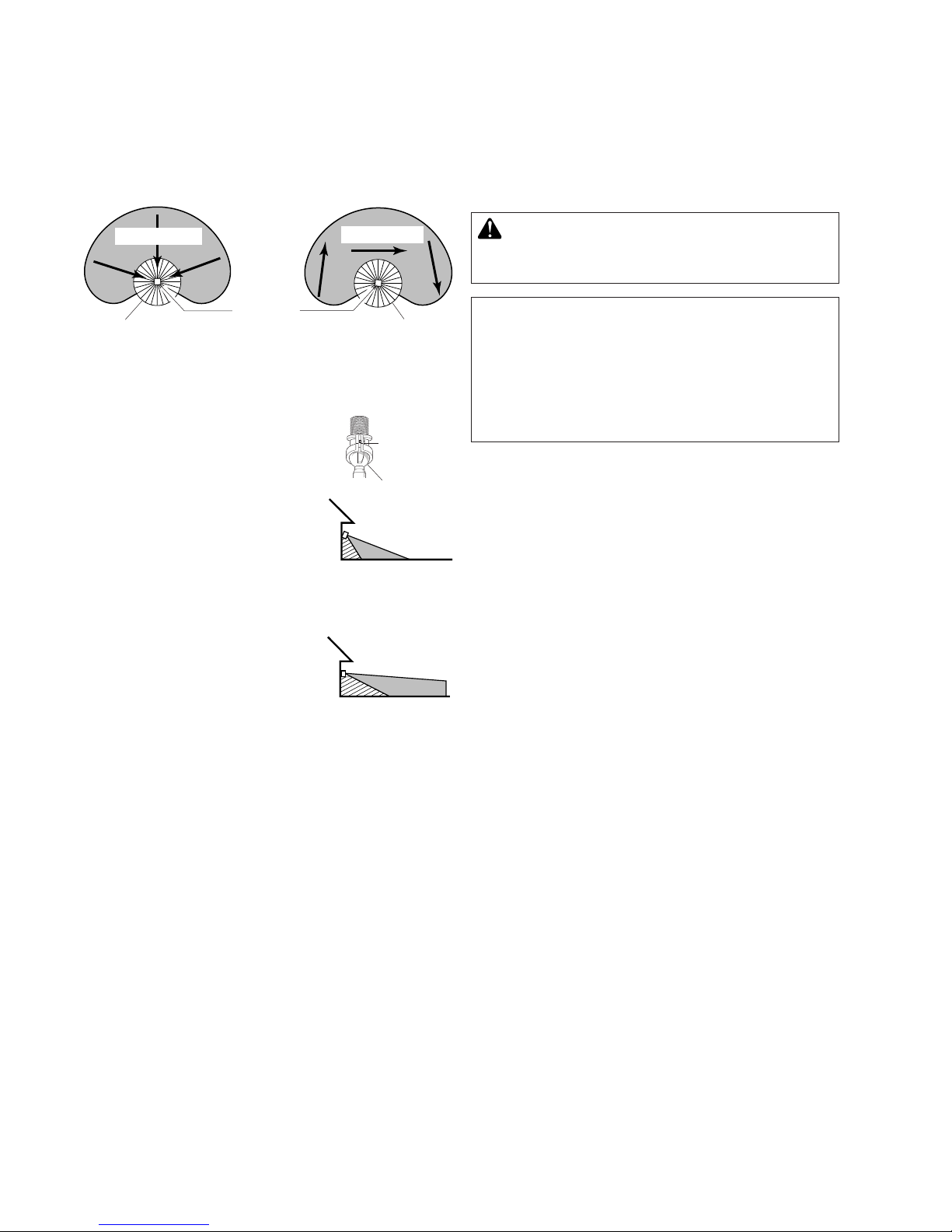
Maximum
Maximum Range Coverage Angle
MAX
MIN
RANGE
ON-TIME DUAL BRITE™
TEST 1 5 20
MINUTES
OFF 3 6 DUSK TO
DAWNHOUR
B
O
O
S
T
Motion
Motion
8ft.
(2.4m)
70ft. 100ft.
(21m) (30.5m)
Boosted
Sensor
240°
Du a l Zo n e ™
Du a l Zo n e ™
Du a l Zo n e ™
Du a l Zo n e ™
Bottom of Sensor
Avoid aiming the control at:
•Objects that change temperature rapidly, such as
heating vents and air conditioners.These heat
sourcescouldcausefalsetriggering.
•Areaswherepets or trafficmaytriggerthecontrol.
•Nearby large, light-colored objectsreectinglight
maytriggertheshut-offfeature.Donotpointother
lightsatthesensor.
Least Sensitive Most Sensitive
NOTE: Du a l Zo n e ™isanewzoneofdetectionwhich
wasaddedasanoptiontoselectHeath®/Zenithmotion
sensingproducts.Thisfeatureaddsazoneofdetec-
tionunderthemotionsensor.Du a l Zo n e ™requires
noadditionaladjustmentandoperatesinconjuction
withtheforward-lookingsensor.
3. Loosentheclampscrewinthe
sensor ball joint and gently
rotatethesensor.
4. Walk through the coverage
area noting where you are
whenthelightsturnon(also,
theLEDwillashseveraltimes
whenmotionisdetected).Move
thesensorheadup,down,or
sidewaystochangethecover-
agearea.Keep the sensor at
least 1" (25 mm) away from
the bulbs.
5. AdjusttheRANGEasneeded.
RANGE set too high may
increasefalsetriggering.
6. Secure the sensor head by
tightening the clamp screw.
Donotovertightenthescrew.
7. SettheamountofTIMEyouwantthelightstostay
onaftermotionisdetected(1,5,or20minutes).
8. SettheDu a l Br i t e ®switchtotheamountoftime
afterduskyouwantthelightsonatlowlevel(Off,
3,6Hrs.,Dusk-to-Dawn).
Clamp
Screw
Ball
Joint
Aim Sensor
Down for Short
Coverage
Aim Sensor
Higher for Long
Coverage
NOTE:
Ifxtureismountedhigherthan8ft.(2.4m),aiming
thesensordownwillreducecoveragedistance.
Thedetectorislesssensitivetomotiondirectlytowardsit.
WARNING - Risk of fire. Do not aim the bulbs
at a combustible surface within 3 ft. (1 m).
TEST AND ADJUSTMENT
1. Turn on the circuit breaker and light switch.
NOTE: Sensor has a 1 1/2 minute warm up period
beforeitwilldetectmotion.Whenrstturned
on,wait11/2minutes.
NOTE: Meetsthe ENERGY STAR® guidelines when
Du a l Br i t e ®functionisoffandON-TIMEis1or5minutes
andwhenusedwith120WMaxbulbs.
2. Turn the RANGE control to the medium position
(halfwaybetweenMINandMAX),Du a l Br i t e ®toOFF,
andtheON-TIMEcontroltotheTESTposition.

5
598-1160-05
SPECIFICATIONS
HorizontalRange. . . . Up to 70 ft. (21 m); 100 ft.
(30.5 m) with Range Boost.
[varies with surrounding
temperature]
VerticalRange . . . . . . Upto15ft.(4.6m)
SensingAngle . . . . . . Upto240°horizontal.Upto80°
Vertical
ElectricalLoad. . . . . . Upto300WattMaximumTung-
stenHalogen[Upto150Watt
Maximumeachbulbholder.]
PowerRequirements . 120VAC,60Hz
OperatingModes. . . . TEST, AUTO, and MANUAL
MODE
TimeDelay . . . . . . . . 1,5,20minutes
Replacementbulb . . . T3, 150W halogen maximum
120VAC
Du a l Br i t e ®Timer . . . . Off,3,6hours,Dusk-to-Dawn
HeathCoLLCreservestherighttodiscontinueprod-
uctsandtochangespecicationsatanytimewithout
incurringanyobligationtoincorporatenewfeaturesin
productspreviouslysold.
Light Shield Installation
Ifyourlightdoesnotcomeonatduskorturnsoffun-
expectedly,thenanotherlightsourcemaybeactivating
thedaytimeshutofffeature.Possiblesourcesoflight
interferencearestreetlights,landscapelighting,other
securitylightsorlanterns,oraninteriorhouselightshin-
ingthroughawindow.Itcouldalsobereectivelight,
suchasfromapoolorlightcoloredwall.
Toinstallthelightshield,followthesesimplesteps.
1. Removeprotectivebackingfromthebottomofthe
lightshield.
2. Position light shield over the photocell with the
openingfacingawayfromtheinterferinglight.
3. Presstheadhesivesidermlyagainstthephotocell
tomountitpermanentlyinplace.
Protective
Backing
Light
Shield

6598-1160-05
TROUBLESHOOTING GUIDE
SYMPTOM POSSIBLE CAUSE SOLUTION
Lights will not come
on.
1. Lightswitchisturnedoff.
2. Lampislooseorburnedout.
3. Fuseisblownorcircuitbreakeristurnedoff.
4. Daylightturn-offisineffect.
5. Incorrectcircuitwiring,ifthisisanewinstallation.
6. Lightcontrolaimedinwrongdirection.
1. Turnlightswitchon.
2. Checkoodlampandreplaceifburnedout.
3. Replacefuseorturncircuitbreakeron.
4. Recheckafterdark.
5. Verifywiringiscorrect.
6. Re-aimlightcontroltocoverdesiredarea.
Lightscomeoninday-
light.
1. Light control may be installed in a relatively dark
location.
2. LightcontrolisinTEST.
1. Thextureisoperatingnormallyunderthesecondi-
tions.
2. Setcontrolswitchto1,5,or20minutes.
Lights come on for no
apparentreason.
1. Lightcontrolmaybesensingsmallanimalsorauto-
mobiletrafc.
2. Rangeissettoohigh.
3. Du a l Br i t e ®timerison.
1. Re-aimlightcontrol.
2. Reducerange.
3. Thextureisoperatingnormallyunderthesecondi-
tions.
Lightsturnofftoolatein
Dusk-to-Dawnsetting.
Lightcontrolmaybeinstalledinarelativelydarkloca-
tion.
Relocatelightcontrol,oruse3hr.or6hr.setting.
Lightsstayoncontinu-
ously.
1. Alampispositionedtooclosetothelightcontrolor
pointedatnearbyobjectsthatcauseheattotrigger
thelightcontrol.
2. Thelightcontrolmaybepickingupaheatsource
likeanairvent,dryervent,orbrightlypainted,heat-
reectivesurface.
3. Lightcontrolisinmanualmode.
1. Repositiontheoodlampawayfromthelightcontrol
ornearbyobjects.
2. Reducerange.
3. SwitchlightcontroltoAUTO.
Lightsashonandoff. 1. Heatorlightfromthelampsmaybeturningthelight
controlonandoff.
2. Heatbeingreectedfromotherobjectsmaybeturn-
ingthelightcontrolonandoff.
3. LightcontrolisintheTESTmodeandwarmingup.
1. Repositiontheoodlampawayfromthelightcon-
trol.
2. Repositionlightcontrol.
3. Flashingisnormalundertheseconditions.
Lightsashonce,then
stay off in manual
mode.
Lightcontrolisdetectingitsownlights. Reposition ood lamps to keep area below the light
controlrelativelydark.

7
598-1160-05
TEN YEAR LIMITED WARRANTY
Thisisa“LimitedWarranty”whichgivesyouspeciclegalrights.Youmayalsohaveotherrightswhichvaryfrom
statetostateorprovincetoprovince.
Foraperiodoftenyearsfromthedateofpurchase,anymalfunctioncausedbyfactorydefectivepartsor
workmanshipwillbecorrectedatnochargetoyou.
Not Covered -Repairservice,adjustmentandcalibrationduetomisuse,abuseornegligence,lightbulbs,
batteries,andotherexpendableitemsarenotcoveredbythiswarranty.Unauthorizedserviceormodica-
tionoftheproductorofanyfurnishedcomponentwillvoidthiswarrantyinitsentirety.Thiswarrantydoes
notincludereimbursementforinconvenience,installation,setuptime,lossofuse,unauthorizedservice,or
returnshippingcharges.
ThiswarrantycoversonlyHeathCoLLCassembledproductsandisnotextendedtootherequipmentand
componentsthatacustomerusesinconjunctionwithourproducts.
THIS WARRANTY IS EXPRESSLY IN LIEU OF ALL OTHER WARRANTIES, EXPRESS OR IMPLIED,
INCLUDINGANYWARRANTY,REPRESENTATIONORCONDITIONOFMERCHANTABILITYORTHAT
THEPRODUCTSAREFITFORANYPARTICULARPURPOSEORUSE,ANDSPECIFICALLYINLIEUOF
ALLSPECIAL,INDIRECT,INCIDENTAL,ORCONSEQUENTIALDAMAGES.
REPAIRORREPLACEMENTSHALLBETHESOLEREMEDYOFTHECUSTOMERANDTHERESHALL
BENOLIABILITYONTHEPARTOFHEATHCOLLCFORANYSPECIAL,INDIRECT,INCIDENTAL,OR
CONSEQUENTIALDAMAGES,INCLUDINGBUTNOTLIMITEDTOANYLOSSOFBUSINESSORPROF-
ITS,WHETHERORNOTFORESEEABLE.Somestatesorprovincesdonotallowtheexclusionorlimitation
ofincidentalorconsequentialdamages,sotheabovelimitationorexclusionmaynotapplytoyou.
Please keep your dated sales receipt, it is required for all warranty requests.
TECHNICAL SERVICE
Please call 1-800-858-8501 (English speaking only) for assistance before returning
product to store.
Ifyouexperienceaproblem,followthisguide.YoumayalsowanttovisitourWebsiteat:www.hzsupport.com.
Iftheproblempersists,call*forassistanceat1-800-858-8501(Englishspeakingonly),8:00AMto5:00PMCST
(M-F).Youmayalsowrite*to:
HeathCo LLC
P.O.Box90045,BowlingGreen,KY42102-9045
ATTN:TechnicalService
*IfcontactingTechnicalService,pleasehavethefollowinginformationavailable:ModelNumber,DateofPur-
chase,andPlaceofPurchase.
No Service Parts Available for this Product
Please keep your dated sales receipt, it is required for all warranty requests.

8598-1160-05
Características
• TecnologíaDu a l Zo n e ™.
• Prendelaluzcuandodetectamovimiento.
• Apagalaluzautomáticamente.
• BulbSaver™-Prolongalavidadelabombillahasta
4vecesconrespectoalasbombillasestándar.Las
bombillasalcanzanlabrillanteztotalenmenosde2
segundos.
• Temporizadorluzdedosniveles,Du a l Br i t e ®
• Lafotocélulamantienelaluzapagadaduranteeldía.
• LEDindicaquesehadetectadomovimiento(durante
eldíaolanoche).
Contenidos del Paquete
Luz halógena gemela con
detector de movimiento y
Du a l Br i t e ®
Requisitos
• Elcontroldeluzrequiere120VCA.
• ParausarelSobrecontrolManual,conecteelcontrol
conuninterruptor.
• Algunos códigos requieren instalación por un
electricista calificado.
• Serecomiendausaresteproductoconelempaque
provistoyconunacajadeempalmemarcadapara
usoenlugareshúmedos.
Detector
Empaquetadura
3conectores
dealambre
1perno
6tornillos
(3dimensiones)
Láminademontaje
Enchufede
caucho
Placa cubertora
FUNCIONAMIENTO
*SeponeenAutomáticoalamanecer.
Para MODO MANUAL:
...préndalo.
1segundo
APAGADO
luego...
Para AUTOMÁTICO:
Para PRUEBA:
Nota:Cuandoloprendaporprimeravezespere11/2
minutoshastaqueelcircuitosecalibre.
Protectorde
lámpara
Colgadorplástico
2Bombillas
Halógenas
©2009HeathCoLLC 598-1160-05S
Elmodomanualfuncionasóloporla
nocheporquelaluzdeldíaponeal
detectorenmodoAUTOMÁTICO.
Apagueelinterruptorporunsegundo
yvuélvaloaprenderparaconmu-
tarentreMODOAUTOMÁTICOy
MANUAL.
Elmodomanualfuncionasóloconel
interruptorON-TIMEenlaposición
1,5o20.
TEST 1 5 20
ON-TIME Du a l Br i t e ®
Pongaelinterruptorde
tiempo (ON-TIME), al
fondo del detector, en
la posición de prueba
(TEST)yDu a l Br i t e ®a
apagado(OFF).
ON-TIME
TEST1 5 20
Ponga el control de tiempo (ON-
TIME)enlaposiciónde1,5o20
minutos.
Modalidad: Atiempo: Trabaja: Día Noche
Prueba 5segundas x x
Autom. 1,5o20min. x
Manual Hastael
amanecer*
x
Adorno 3,6horas,hasta
elamanecer
x
Off 3 6 Duskto
Dawn
Cumple con las normas ENERGY
STAR®cuandolafunciónDu a l Br i t e ®
estáapagadaylafaseON-TIMEestá
calibradapara1o5minutosycuando
seusabombillasde120Wmáximo.
ModeloSH-5512

9
598-1160-05
CUIDADO: Para evitar los peligros de incen-
dio o quemazón:
• Dejequeelelementoseenfríeantesdetocarlo.Labom-
billayelelementofuncionanaaltastemperaturas.
• Mantengaalelementoporlomenosa25mmde
losmateriales combustibles. No lo apunte hacia
objetosqueesténmáscercade1m.
• UsesólolámparashalógenasdetungstenodeT3,
de78mmy150vatiosmáximo.
Para una fácil instalación escoja una luz con un
interruptor de pared. IMPORTANTE: No lo use con
temporizadoresoatenuadoresdeluz.
Para un mejor funcionamiento, instale el aparato a
casi2.4m del suelo.NOTA:Sielaparatoestáinstalado
amásde8pies(2.4m),siseapuntaeldetectorhacia
abajosereduciráladistanciadecobertura.
❒ Gire la cabeza del detector hacia la unión del
tornillosujetador.
Sóloparamontajeeléctrico:
Controles
TornilloSujetador
❒ Entoncesgirelacabezadeldetectorhacialaderecha
por180°hastaqueloscontrolesmirenhaciaabajo.
Sieldetectorsesaledelauniónesférica,aojeel
tornillosujetadoryempujeeldetectorhaciadentro
de la unión esférica. Apriete el tornillo sujetador
cuandotermine.
Mueva el interruptor de
tiempo (ON-TIME) a 1, 5 o 20
minutos
Apague el interruptor por
un segundo y préndalo
de nuevo
Resumen de las modalidades del interruptor
* Siseconfundemientrascambiadefases,apague
laelectricidadporunminutoypréndaladenuevo.
Despuésdeltiempodecalibraciónelcontrolestará
enfaseAUTO(MÁTICA).
PRUEBA
AUTOM.
MODO
MANUAL
INSTALACION
CUIDADO: Mantenga al detector por lo menos
a 25 mm de las lámparas.
Luz de Adorno (Du a l Br i t e ®)
Laluzseprendeconmediabrillantezporeltiempo
escogido después del atardecer (apagado, 3 horas,
6 horas,hasta el amanecer). Si escoge OFF (APA-
GADO) deshabilita esta función. Las funciones que
detectanmovimientocontinuarán funcionando como
sedescribenenestemanual.Sidetectamovimiento,
laluzseprendecontodosuresplandorporeltiempo
deduraciónodeON-TIME(1,5o20minutos)yluego
regresaamedialuz.
Controles
Controles
Montaje en pared Montaje en alero
NOTA:Lalámparayelsensordebemontarsecomo
seindicaarriba,unavezinstalado(segúneltipode
instalación).
Antes de instalar la lámpara bajo un alero,la cabeza
del sensor debe rotarsecomosemuestraenlosdos
pasossiguientesparalacorrectaoperaciónyevitarel
riesgodedescargaeléctrica.
IMPORTANTE: Para un funcionamiento correcto
debajo del alero, instale el protector de la luz
(incluido). Vea Instalación del Protector de la luz
para más detalles.

10 598-1160-05
Instalación y Cambio de la Bombilla Conecte el Control de Luz
Blanco a Blanco
Negro a Negro
Empaquetadura
láminade
Montaje
Pernode
Montaje
Enchufede
Caucho
Conecte los alambres del aparato, propuestos
para conexión a tierra, a la conexión a tierra de
la caja de enpalme.
ADVERTENCIA: Desconecte la energía en el
disyuntor. Ponga la cinta adhesiva sobre el inte-
rruptor del disyuntor y verifique que el aparato
esté apagado.
1. Quiteelaparatodeluzexistente.
2. Instalelaláminademontajealacajadeempal-
meusandotornillosapropiadosparalacajade
empalme.
3. Sepuedeusarelcolgadorplásticoparasostener
elaparatomientrasseinstalaelcableado.Elex-
tremopequeñodelcolgadorsepuedepasarpor
elagujeroenelcentrodelaplacacubertora.El
extremopequeñovaluegodentrodelasranuras
delaláminademontaje.
4. Pasetodosloscablesdelaparatoporlosagujeros
grandesdelempaque,comosemuestra.
5. Conecte los cables de la caja de empalme con
loscablesdelaparatodeluz,comosemuestra.
Tuérazalosjuntosyasegúrelosconun conector
decables.
1
2
Enchufe
izquierdo Enchufe
derecho
Contacto
Bombilla Cabezalde
lalámpara
Tapade
vidrio
CUIDADO:Cuandocambielabombilla,apague
la energía y deje que el aparato se enfríe.
NOTA: Las bombillas se incluyen pero deben ser
instaladas.Lasbombillasseencuentrandetrásdela
cobertura de vidrio de cada cabezal de lámpara.
Utiliceunguantelimpioountrapocuandoestémani-
puladoelfoco.
Usealcoholetílicoparalimiarlabombillasilahatocado
consusmanosdesprotegidas.
1. Abraelcabezaldelalámparaconundestornilla-
dorPhillips.Parasacarlabombillavieja,empújela
hacialaderechahastaqueelladoizquierdodela
bombillaestéfueradelenchufeizquierdo.
2. Parainstalarlabombilla,pongaunextremodela
bombillasobre el contacto delenchufe derecho.
Mientras empuja la bombilla contra el contacto
derecho,bajeelotroextremodelabombillasobre
elcontactodelenchufeizquierdo.
3. Girelabombillaparavericarqueestécorrecta-
menteasentada.
4. Cierreelcabezaldelalámparayajustebienel
tornilloderetención.

11
598-1160-05
Instale el Control de Luz
1. Pongaelpernodemontajeatravésdelfrentede
latapadelacajadeempalme.Empujeelagujero
pequeñodelaempaquetadurasobreeltornillode
montaje.
2. Asegúresedequelos conectoresdecableylos
cablesesténdentrodelacajadeempalme.Alinee
eltornillodemontajeconelagujerocentraldela
láminademontaje.Asegureelaparatoalalámina
demontaje.
3. Empujeeltapóndecauchormementehastaque
encaje.
4. Sinose usóunacaja deempalmeen unlugar
húmedo,calafatee la superficie de montaje de
la placa de la pared con un sellador de silicona
contra la intemperie.
5. Acomodeloscabezalesdelalámparaaojando
lascontratuercasperonogireloscabezalesdela
lámparamásde180°desuconguraciónhecha
en fábrica. El tornillo de retención debe estar
arribayloscabezalesdelalámparadebenestar
horizontales.
Mantengaloscabezalesde
lalámparaporlomenosa1"
(25mm)deldetector.
Presioneeltapóndecaucho
porsobreeltornillode
montaje.
Tornillo de
retención
Angulo de
Alcance Máximo Cobertura Máxima
MAX
MIN
RANGE
ON-TIME DUAL BRITE™
TEST 1 5 20
MINUTES
OFF 3 6 DUSK TO
DAWNHOUR
B
O
O
S
T
8pies
(2.4m)
30.5m
(Aumentode
Distancia)
70pies
(21m)
240°
Du a l Zo n e ™
Parte de abajo del detector
Evite apuntar el control hacia:
•Objetosquecambienrápidamentedetemperatura
talescomoductos de calefacción y acondiciona-
dores de aire.Estasfuentesdecalorpuedencausar
falsasalarmas.
•Áreas donde animales domésticos o el tráfico
puedanactivarelcontrol.
•Los objetos grandes cercanos y de colores res-
plandecientes que reejan la luz del día pueden
hacerqueeldetectorseapague.Noapunteotras
luceshaciaeldetector.
Du a l -
Zo n e ™
PRUEBA Y AJUSTE
1. Prenda el cortacircuitos y el interruptor de luz.
NOTA: Eldetectortieneunperíododecercade11/2
minutosdecalentamientoantesdedetectar
movimiento. Cuando lo prenda por primera
vez,espere11/2minutos.
NOTA:CumpleconlasnormasENERGYSTAR®cuando
lafunciónDu a l Br i t e ®estáapagadaylafaseON-TIME
estácalibradapara 1 o 5 minutosycuandoseusa
bombillasde120Wmáximo.
2. GireelcontroldeALCANCE(RANGE)alaposición
media(entreMINyMAX),DualBrite®aOFF,yel
controldeDURACIÓN(ON-TIME)alaposiciónde
PRUEBA(TEST).
12 598-1160-05
3. Aojeeltornillosujetadorenla
uniónesféricaygiredespacio
eldetector.
4. Camine por el área a prote-
gerse y dése cuenta dónde
estácuandoseprendelaluz
(además, el LED destellará
variasvecescuandosedetecta
movimiento).Muevalacabeza
deldetectorhaciaarriba,hacia
abajo o hacia los lados para
cambiareláreadeprotección.
Mantenga al detector por lo
menos a 1 pulgada (25 mm)
de las lámparas.
5. Fije la sensibilidad (RANGE)
como necesite. Demasiada
sensibilidad puede aumentar
lasfalsasalarmas.
6. Asegure la puntería de la ca-
bezadeldetector ajustando el tornillo sujetador.
Noloaprietedemasiado.
Detector
Movimiento
Movimiento
NOTA: Du a l Zo n e ™esunanuevazonadedetección
quefueañadidacomounaopciónparaescogerlos
productosdetectoresdemovimientoHeath®/Zenith.
Esta característica añade una zona de detección
debajodeldetectordemovimiento.Du a l Zo n e ™ no
requiereningúnajusteadicionalyfuncionajuntocon
eldetectorquemirahaciaadelante.
Tornillo
Sujetador
Unión
Esférica
Apunte el
detector hacia
abajo para poca
cobertura
Apunte el
detector más
arriba para
mayor cobertura
Du a l Zo n e ™
Lo menos sensible Lo más sensible
Du a l Zo n e ™
NOTA:Sielaparatoestáinstaladoamásde8pies(2,4
m),siseapuntaeldetectorhaciaabajosereducirála
distanciadecobertura.
Eldetectoresmenossensibledelmovimientoquese
dirigehaciaél.
ADVERTENCIA:Riesgodeincendio.Noapunte
las lámparas a superficies combustibles dentro
de un 3 pies (1 m).
7. Fijeelperíododetiempo(ON-TIME)quelaluzdebe
quedarseprendidadespuésdedetectarmovimiento
(1,5o20minutos).
8. Paraunailuminaciónornamentaldebajaintensidad,
pongaelinterruptordeDu a l Br i t e ®enlaposiciónde3,
6,odelDusk-to-Dawn(atardecer-al-amanecer).

13
598-1160-05
ESPECIFICACIONES
Alcancehorizontal .......Hasta70pies(21m),Aumento
de Distancia prendido. Hasta
100 pies (30.5 m), Aumento
de Distancia apagado. (varía
conlatemperaturadelmedio
ambiente).
Alcancevertical ........... Hasta15pies(4,6m)
Angulodedetección....Hasta 240° horizontal. Hasta
80°vertical
CargaEléctrica............ Hastahalógenosdetungsteno
demáximo300vatios[Hasta
150VatiosMáximoporcada
portalámparas].
RequisitosdeEnergía . 120VCA,60Hz
ModosdeOperación ...PRUEBA, AUTOMÁTICO y
MODOMANUAL
RetardodeTiempo...... 1,5,20minutos
Lámparade
repuesto.......................Halógena T3 de 150 vatios,
máx.De120VCA
Temporizador
Du a l Br i t e ®...................Apagado,3,6horas,delatar-
deceralamanecer
HeathCoLLCsereservaelderechodedescontinuar
productosydecambiarespecicacionesacualquier
momentosinincurrirenningunaobligacióndetener
queincorporarnuevascaracterísticasenlosproductos
vendidosconanterioridad.
Instalación del Protector de Luz
Silaluznoseprendealanocheceroseapaga
inesperadamente,otrafuentedeluzpuedeestar
activandoelelementodeapaguedeldía.Lasposi-
blesfuentesdeinterferenciadeluzsonlaslucesde
lacalle,elalumbradodelosjardines,otraslucesde
seguridadofaroles,olaluzinteriordeunacasaque
brillaatravésdeunaventana.Puedetambiénser
unaluzreectante,comoeldeunapiscinaopared
decolorbrillante.
Parainstalarelprotectordelaluz,sigaestospasos
sencillos.
1. Quiteelprotectoradhesivodelaparteinferiordel
protectordelaluz.
2. Pongaelprotectordelaluzsobrelafotocélulacon
suaberturahaciaelotroladodelaluzdeinterfe-
rencia.
3. Presionermementeelladoconlacintaadhesiva
contralafotocélulaparamontarlapermanentemente
ensusitio.
Protector
adhesivo
Protector
delaluz

14 598-1160-05
GUIA DE INVESTIGACION DE AVERIAS
SÍNTOMA POSIBLE CAUSA SOLUCIÓN
LaLuznoseenciende. 1. Elinterruptordeluzestáapagado.
2. Elfaroestáojooquemado.
3. El fusible está quemado o el cortacircuitos está
apagado.
4. Ladesconexióndeluzdeldíaestáenefecto.
5. Alambradoincorrecto,siéstaesunanuevainstala-
ción.
6. Elcontroldeluzestáapuntandoendireccióninco-
rrecta.
1. Enciendaelinterruptordeluz.
2. Reviseelfaroycambiesiestáquemado.
3. Cambieelfusibleenciendaeldisyuntor.
4. Compruébelocuandocomiencelaobscuridad.
5. Veriquequeelcableadoestécorrecto.
6. Vuelvaaapuntarelcontroldeluzparaquecubrael
áreadeseada.
Laluzseprendedurante
eldía.
1. ElControldeLuzpuedeestarinstaladoenunlugar
relativamenteoscuro.
2. ElControldeLuzestáenfasedePrueba.
1. Elaparatoestáfuncionandonormalmentebajoestas
condiciones.
2. Fijeelinterruptordecontrola1,5o20minutos.
La luz se prende sin
ninguna razón apa-
rente.
1. ElControldeLuzpuedeestardetectandoanimales
pequeñosoeltrásitodeautomóviles.
2. Elmargenestápuestomuyalto.
3. EltemporizadorDu a l Br i t e ®estáencendido.
1. Reapunteelcontroldeluz.
2. ApagueelAumentodeDistancia.
3. Elartefactoestátrabajandonormalmentebajoestas
condiciones.
La luz se apaga muy
tardeenlacalibración
delAnocheceralAma-
necer.
Elcontroldeluzdebeinstalarseenunsitiorelativa-
menteoscuro.
Reubiqueelcontroldeluzouseunajustede3o6
horas.
Laluzsequedaprendida
continuamente.
1. Elfaroestámuycercadelcontroldeluzoapuntando
aobjetoscercanosquegenerancaloryactivanel
controldeluz.
2. El Control de Luz está apuntando hacia una fuente
decalortalcomounconductodeaire,desecadorao
haciaunasupercieconpinturabrillanteyquereeja
elcalor.
3. Elcontroldeluzestáenelmodomanual.
1. Reubiqueelfarolejosdelcontroldeluzodeobjetos
cercanos.
2. ApagueelAumentodeDistancia.
3. CambieelcontroldeluzaAUTO.
La luz se prende y se
apaga.
1. Elcalorolaluzdelosfarospuedeestarencendiendo
yapagandoelcontroldeluz.
2. El calor reejado por otros objetos puede estar
encendiendoyapagandoelcontroldeluz.
3. ElControldeLuzestáenfasedePruebaycalen-
tándose.
1. Reubiqueelfarolejosdelcontroldeluz.
2. Reubiqueelcontroldeluz.
3. Elprenderseyapagarseesnormalbajoestascon-
diciones.
Laluzseprendeunavezy
luegopermaneceapaga-
daenlafaseManual.
Elcontroldeluzestádetectandosupropialuz. Reubiquelosfarosparamantenerrelativamenteobscura
lazonadebajodelalámpara.

15
598-1160-05
GARANTÍA LIMITADA A 10 AÑOS
Estaesuna“GarantíaLimitada”queledaaUd.derechoslegalesespecícos.Ustedpuedetambiéntener
otrosderechosquevaríandeestadoaestadoodeprovinciaaprovincia.
Porunperíodode10añosdesdelafechadecompra,cualquiermalfuncionamientoocasionadoporpartes
defectuosasdefábricaomanodeobraserácorregidosincargoparaUd.
No cubierto -Serviciodereparación,ajusteycalibracióndebidoalmaluso,abusoonegligencia,bombi-
llas,baterías,uotraspartesfungiblesnoestáncubiertasporestagarantía.LosServiciosnoautorizados
omodicacionesdelproductoodecualquiercomponentequeseproveeinvalidaránestagarantíaensu
totalidad.Estagarantíanoincluyereembolsoporinconveniencia,instalación,tiempodeinstalación,perdida
deuso,servicionoautorizado,ocostosdetransportederetorno.
EstagarantíacubresolamentelosproductosensambladosporHeathCoLLCynoseextiendeaotrosequi-
posocomponentesqueelconsumidorusajuntoconnuestrosproductos.
ESTAGARANTÍAESTÁEXPRESAMENTEENLUGARDEOTRASGARANTÍAS,EXPRESADASOSO-
BREENTENDIDAS, INCLUYENDO CUALQUIER GARANTÍA, REPRESENTACIÓN O CONDICIÓN DE
COMERCIABILIDADOQUELOSPRODUCTOSSEADAPTENPARACUALQUIERPROPÓSITOOUSO
ENPARTICULAR,YESPECIFICAMENTEENLUGARDETODOSLOSDAÑOSESPECIALES,INDIREC-
TOS,INCIDENTALESYCONSECUENTES.
LAREPARACIÓNOELREEMPLAZODEBERÍASERLAÚNICASOLUCIÓNDELCLIENTEYNOHABRÁ
RESPONSABILIDADPORPARTEDEHEATHCOLLCPORCUALQUIERDAÑOESPECIAL,INDIRECTO,
INCIDENTALOCONSECUENTE,INCLUIDOSPERONOLIMITADOSACUALQUIERPÉRDIDADENE-
GOCIOOGANACIASSEANONOPREVISIBLES.Algunosestadosoprovinciasnopermitenlaexclusión
olimitacióndedañosincidentalesoconsecuentes,demodoquelalimitaciónoexclusiónarribaindicada
puedequenoseapliqueaUd.
Por favor guarde su recibo de venta fechado; se lo requiere para cualquier solicitud de garantía.
SERVICIO TÉCNICO
Favor de llamar al 1-800-858-8501 (sólo para hablar en inglés) para pedir ayuda antes
de devolver el producto a la tienda.
Sitienealgúnproblema,sigaestaguía.UstedpuedetambiénvisitarnuestrositioWeb:www.hzsupport.com.
Sielproblemacontinúa,llameal1-800-858-8501(sóloparahablareninglés),de8:00AMa5:00PMCST(L-
V).Ustedpuedetambiénescribira:
HeathCo LLC
P.O.Box90045,BowlingGreen,KY42102-9045
ATTN:TechnicalService(ServicioTécnico)
*SisellamaalServicioTécnico,porfavortenerlistalasiguienteinformación:NúmerodeModelo,Fechade
comprayLugardecompra.
No hay piezas de servicio disponibles para este producto.
Por favor guarde su recibo de venta fechado; se lo requiere para cualquier solicitud de garantía.

16 598-1160-05
Commande
d’éclairage
Plaque de garde
Détecteur
3serre-ls
6visincluses
(3formats)
Garniture
dejoint
Visdemontage
Bouchonde
caoutchouc
FONCTIONNEMENT
Écrande
protection
Bridedemontage
2Ampoules
halogènes
Crochetenplastique
*Revientaumodeautomatiqueauleverdusoleil.
Luminaire halogène
double à détecteur de
mouvement Du a l Br i t e MD
Caractéristiques
• TechnologieDu a l Zo n e MC.
• Allumel’éclairagelorsqu’unmouvementestdétecté.
• Éteintautomatiquementl’éclairage.
• BulbSaverMC-Duréedeviedesampoulesjusqu’à4
foissupérieureauxampoulesstandard.Lesampoules
s’allumentenmoinsde2secondespourunéclairage
ultralumineux.
• MinuteriedeDu a l Br i t e MD.
• Photocellulequimaintientl’éclairageéteintpendant
lapériodedelumièredujour.
• LaDELindiquequ'unmouvementaétédétecté(jour
ounuit).
Contenu de l’emballage
ESSAI
TEST 1 5 20
ON-TIME Du a l Br i t e MD
Placer l'interrupteur de
tempsencircuit(ON-TI-
ME)àlabaseducapteur
àTESTet l’interrupteur
Du a l Br i t e MDàOFF.
PRIORITÉ MANUELLE
ON-TIME
TEST1 5 20
...ànouveau
encircuit
AUTOMATIQUE
horscircuit
pendant1
seconde,
puis ...
Lemodemanuelnefonctionneque
lanuitparcequelalumièredujour
remetlecapteurenmodeAUTO.
Mettrel’interrupteurhorscircuitpen-
dant une seconde, plus en circuit
pouralternerentrelesmodesAUTO
etMANUEL.
Lemodemanuelnefonctionneque
lorsque l’interrupteur ON-TIME est
auxpositions1,5ou20.
Amenerl’interrupteurdetempsen
circuit(ON-TIME)àlapositioncor-
respondantà1,5ou20minutes.
Mode: Tempsencircuit: Enfonction: jour nuit
Essai 5Secondes x x
Auto 1,5ou20Minutes x
Manuel auchoix,amanecer*x
Accen-
tuation
3,6hjusqu’àl’aurore x
©2009HeathCoLLC 598-1160-05F
NOTE: Aprèsmiseencircuit,attendreenron11/2mi-
nutepourquel’étalonnageducircuitsoitcom-
plété.
Off 3 6 Duskto
Dawn
Exigences
• Lacommanded’éclairagenécessiteunealimentation
de120Vc.a.
• Pourutiliserlaprioritémanuelle,raccorderlacom-
mandeàuninterrupteur.
• Certains codes de bâtiment locaux peuvent exi-
ger que l’installation soit faite par un électricien
qualifié.
• Ceproduitestconçupourêtreutiliséavecuneboîte
dejonctionportantuneindicationd’utilisationpossible
enmilieuhumide.
Conforme aux exigences ENERGY
STARMDlorsque la fonctionDu a l Br i -
t e MDestdésactivée,queleparamètre
ON-TIMEestrégléà1ou5minutes
etquevousutilisezunelampede120
Wmaximum.
ModèleSH-5512

17
598-1160-05
Placer l’interrupteur ON-TIME
à 1, 5 ou 20 minutes
Mettre l’interrupteur
hors circuit pendant
une seconde, puis le
remettre en circuit*
* Sivousnesavezplusdansquelmodesetrouvel’appareil,
couperl’alimentationpendantuneminutepuislarétablir.
Aprèsletempsd’étalonnage,lacommandereviendraau
modeAUTO.
PRIORITÉMANUELLE
AUTO
TEST
Résumé du mode de commutation
Pourfaciliterl’installation,choisirunappareild’éclairage
devantêtreremplacéetquiestdéjàcommandéparun
interrupteur.IMPORTANT :NePASutiliseravecdes
gradateursdelumièreoudesminuteries.
Pour assurer un rendement optimum, monter le
luminaire à environ 2,4 m au-dessus du sol. NOTE :
Lorsqueleluminaireestinstalléàunehauteursupérieure
à8pi(2,4m),lefaitdedirigerledétecteurverslebas
réduitlaportéedelacouverture.
AVERTISSEMENT : Pour éviter les risques
de brûlure ou d'incendie
• Laisser l’appareil refroidir avant de le toucher.
L’ampouleetl’appareilfonctionnentàhautetem-
pérature.
• Garderl’appareilàaumoins5mmdesmatériaux
combustibles.Nepaspointerversdesobjetsàmoins
de1m.
• Utiliserseulementdesampouleshalogènesàdeux
brochesT3autungstène,de150wattsmaximum,
120 Vca.
❒ Fairepivoterlatêtedudétecteurendirectiondu
jointàvisdeblocage.
Siledétecteursortdelarotule,desserrerlavisde
blocageetré-insérerledétecteurdanslarotuleet
resserrerlavis.
❒ Puisfairepivoterledétecteursur180°defaçon
quelescommandessoienttournéesverslebas.
INSTALLATION
AVERTISSEMENT : Ne pas permettre au
détecteur d’être à moins de 25 mm des lampes.
Commandes
VisDeBlocage
Pourmontagesousavant-toitseulement:
Minuterie Du a l Br i t e MD
Lalumières’allumeàmi-intensitépourletempschoisi
aprèslecrépuscule[Off(horscircuit)3h,6h,jusqu’à
l’aurore].Pourdésactivercettefonction,placezlecom-
mutateuràOFF.Lafonctiondedétectiondemouvement
continueratoutefoisdefonctionnertelquedécritdansce
guide.Siunmouvementestdétecté,lalumières’allume
àpleineintensitépourletemps(ON-TIME)choisi(1,5
ou20minutes),puisrevientenmodefaibleintensité.
Commandes
Commandes
Montage mural Montage sous
avant-toit
NOTE :Leluminaireetcapteurdevraientêtremontés
commemontréci-dessusaucoursdel'installation(selon
letyped'installation.)
Avant d'installer le luminaire sous l'avant-toit, le
capteur doit être tournécommedémontrédansles
deuxétapessuivantespouruneopérationfonctionelle
etpouréviterlerisquedechocélectrique.
IMPORTANT : Pour un bon fonctionnement sous
avant-toit, installez un pare-lumière (inclus). Voir
Installation de Pare-lumière pour des détails.

18 598-1160-05
Installation et Remplacement
de la Lampe
MISE EN GARDE : Coupez l’alimentation
au disjoncteur ou au fusible. Placez le ruban
sur l’interrupteur de circuit et vérifiez que
l’alimentation est coupée du dispositif.
Câblage de la Commande D’Éclairage
noir / noir
blanc / blanc
Garnituredejoint
Bridede
montage
Visde
montage
Bouchonde
caoutchouc
Raccorder le(s) fil(s) de terre du luminaire et la
vis de terre de la plaque de garde au fil de terre
de la boîte de jonction.
1. Enleverl’appareild’éclairageexistant.
2. Installerlabridedemontagesurlaboîtedejonction
aveclesvisappropriées.
3. Lecrochetenplastiquepeutserviràsupporterle
luminairependantlecâblage.Lepetitboutducro-
chetenplastiquepeutêtreinsérédansletrouau
centredelaplaquedecouverture.Ensuite,lepetit
boutestinsérédansunedesfentesdelabarrede
montage.
4. Fairepasserles lsdel’appareild’éclairagepar
les grosses ouvertures de la garniture, comme
montré.
5. Raccorderleslsdelaboîtedejonctionauxlsde
l’appareild’éclairage.Lestorsaderensembleetles
xeravecunserre-ls.
AVERTISSEMENT : Avant de remplacer une
ampoule, couper l’alimentation et attendre que
l’appareil refroidisse.
NOTE : Les ampoules sont incluses, mais elles
doivent être installées. Les ampoules se trouvent
derrière le couvercle en verre de chaque tête de
lampe.
Utilisezungantouunchiffonproprepourremplacer
lesampoules.
Utilisezdel’alcoolisopropylique(àfriction)pournettoyer
l’ampoulesicelleciaététouchéeàmainsnues.
1. Ouvrezlatêtedelampeavecuntournevisàtête
Phillips.Pourretirerl’ampouleusée,pousserl’am-
pouleversladroitejusqu’àcequelecôtégauche
del’ampoulesoitbienloindeladouillegauche.
2. Pourinstallerl’ampoule,placezuneextrémitéde
l’ampoulesurlecontactdansladouilledroite.Touten
poussantl’ampoulecontrelecontactdroit,baissez
l’autreextrémitédel’ampoulesurlecontactdans
ladouillegauche.
3. Tournezl’ampoulepourvérierqu’elleestinstallée
correctement.
4. Fermezlatêtedelampeetserrezbienlavisde
verrouillage.
1
2
Douillede
Gauche Douillede
Droite
Contact
Ampoule TêtedeLampe
Couvercle
enVerre

19
598-1160-05
Montage de la Commande D’Éclairage
1. Insérerlavisdemontagedansletrouducouvercle
delaboîtedejonction.Pousserlepetittroudela
garnituresurlavisdemontage.
2. S’assurerquelesserre-lsetleslssetrouvent
àl’intérieurdelaboîtedejonction.Alignerlavis
demontagesurlecentredutroudelabridede
montage.Fixerl’appareilàlabridedemontage.
3. Poussezlebouchondecaoutchoucfermementen
place.
4. Si le boîtier n’est pas étanche aux intempéries,
calfeutrer la plaque murale et la surface de
montageavecunscellantsilicone.
5. Réglezlestêtesdelampeendesserrantlesécrous
deverrouillage,maisnetournezpaslestêtesde
lampe de plus de 180° par rapport au réglage
d’usine.Lavisdeverrouillagedoitêtreau-dessus
etlestêtesdelampedoiventêtreàl’horizontale.
Gardezlatêtedelampeàau
moins1"(25mm)ducapteur.
Pousserlecapuchondecaoutchouc
surlavisdemontage.
VisdeVerrouillage
Portée maximale Angle de couverture
maximale
MAX
MIN
RANGE
ON-TIME DUAL BRITE™
TEST 1 5 20
MINUTES
OFF 3 6 DUSK TO
DAWNHOUR
B
O
O
S
T
2,4m
21m 30,5m
(avecintensicateur)
240°
Du a l Zo n e MC
Bas du détecteur
Éviter de pointer l’appareil:
•endirectiond’objetsdontlatempératurechangera-
pidement,telsquedes bouches d’air chaud et des
climatiseurs.Detellessourcesdechaleurpeuvent
provoquerdesdéclenchementsintempestifs.
•versdesendroitsoùdes animaux,desvéhicules ou
des passantspeuventdéclencherlacommande.
•surde grands objets clairs à proximitéquiréé-
chissentlalumièredujouretrisquentdedéclencher
ledispositifd’arrêt.Nepaspointerd’autresappareils
d’éclairageversledétecteur.
Du a l Zo n e MC
ESSAIS ET RÉGLAGES
1. Mettre en circuit le disjoncteur et l’interrupteur
d’éclairage.
NOTE: Lecapteurdoitseréchauffer11/2minuteavant
depouvoirdétecterlemouvement.Lorsque
l’appareil est mis en circuit, attendre 1 1/2
minute.
NOTE: Conforme aux exigences ENERGY STARMD
lorsquelafonctionDu a l Br i t e MDestdésactivée,quele
paramètreON-TIMEestrégléà1ou5minutesetque
vousutilisezunelampede120Wmaximum.
2. PlacezleboutonRANGEenpositionmédiane(à
mi-cheminentreMINetMAX),leboutonDu a l Br i t e MD
àOFFetleboutonON-TIMEàTEST.

20 598-1160-05
3. Desserrer la vis de blocage
delarotuleetfairepivoterle
détecteurpourpointer.
4. Marcherdanslazonedecou-
vertureetnoteràquelendroit
l’éclairagesedéclenche(de
plus,levoyantàDELclignote
àplusieursrepriseslorsdela
détection d’un mouvement).
Déplacerlatêtedudétecteur
verslehaut,lebasoulecôté
pourmodierlazonedecou-
verture.Ne pas permettre au
détecteur d’être à moins de
25 mm des lampes.
5. Réglerlasensibilité(RANGE)
selon les besoins. Une trop
grande sensibilité pourrait
causer des déclenchements
intempestifs.
Du a l Zo n e MC
NOTE :LatechnologieDu a l Zo n e MCestajoutéede
façonoptionnelleàcertainsproduitsàdétecteurde
mouvementdeHeathMD/Zenith.Cettefonctionajoute
unezonede détectionsous le détecteur de mou-
vement. La technologie Du a l Zo n e MC n’exige aucun
réglageadditionneletfonctionneaveclesdétecteurs
demouvementsclassiques.
Le moins sensible Le plus sensible
Détecteur
Mouvement
Visde
blocage
Rotule
Pointer le détec-
teur vers le bas
pour réduire la
couverture
Pointer le détec-
teur vers le haut
pour augmenter
la couverture
Du a l Zo n e MC
Mouvement
NOTE :Lorsqueleluminaireestinstalléàunehauteur
supérieureà8pi(2,4m),lefaitdedirigerledétecteur
verslebasréduitlaportéedelacouverture.
Ledétecteurestmoinssensibleaumouvementdans
sadirection.
AVERTISSEMENT:Risque d’incendie ! Ne pas
pointer les lampes vers une surface combustible
située à moins de 1 mètre.
6. Fixer la tête du détecteur en position en serrant
la vis de blocage.Éviterdetropserrerlavis.
7. Placer l’interrupteur ON-TIME à 1, 5 ou 20
minutes.
8. Réglerl'interrupteurDu a l Br i t e MDautempsd’allu-
magedésiré,àfaibleintensité,aprèslecrépuscule
(3h,6h,crépuscule-aurore).
Table of contents
Languages:
Other Health Zenith Floodlight manuals

Popular Floodlight manuals by other brands

Light Emotion
Light Emotion P645QUADO User instruction manual

brennenstuhl
brennenstuhl JARO SERIES operating instructions

Saxby
Saxby 11224 quick start guide

Wasserstein
Wasserstein 3-in-1 Smart Floodlight, Charger & Mount for Wyze Cam... user manual

American DJ
American DJ LED Color Ball Features

Chauvet
Chauvet VATION F-165WW Quick reference guide

Chauvet
Chauvet COLORdash Par-Hex 7 Quick reference guide

Steren
Steren LAM-735 instruction manual

Larson Electronics
Larson Electronics EPLC2-LED-150W-RT-JB2-25C instruction manual

Chauvet DJ
Chauvet DJ Mini Kinta ILS Quick reference guide

ADJ
ADJ Par ZP100 3K user manual

Westgate
Westgate LF4PRO-50-150W-MCTP Installation instructions manual


