Healthy Climate Solutions HCC-14-23 User manual
IAQ - AIR FILTRATION
508028-01
12/2019
Supersedes 505,132M
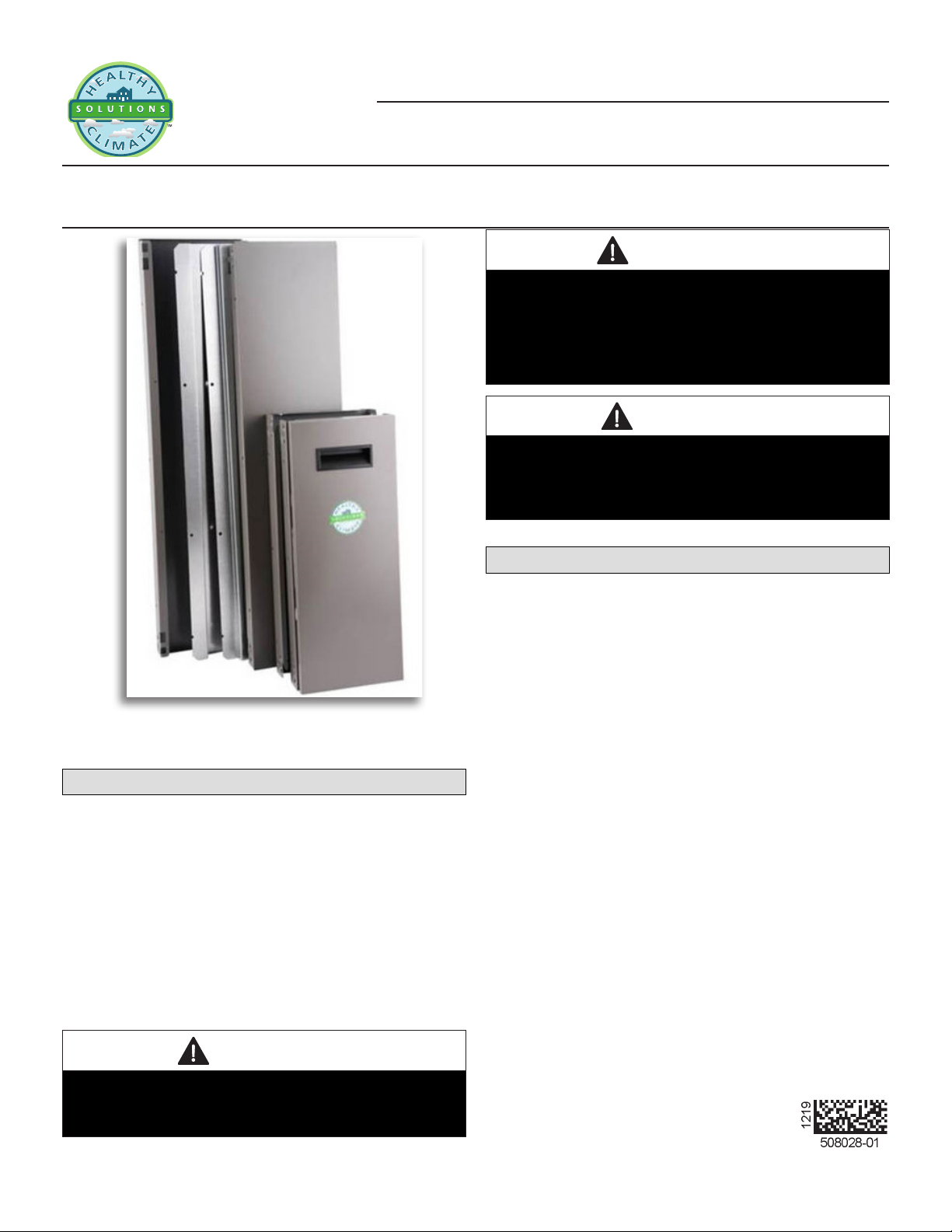
HEALTHY CLIMATE®
MEDIA AIR CLEANER
INSTALLATION INSTRUCTIONS AND HOMEOWNER GUIDE FOR HEALTHY CLIMATE®
CABINETS MODELS HCC-14-23, HCC16-28, AND HCC20-28
THIS MANUAL MUST BE LEFT WITH THE OWNER
FOR FUTURE REFERENCE
Shipping and Packing List
Package 1 of 1 contains:
2 - Side panels
2 - Side rails
1 - Front panel
1 - Rear panel
1 - Door
8 - #8 screws
1 - Installation instructions
1 - Lennox logo label
1 - Warranty sheet
CAUTION
Sharp Edges Hazard.
Equipment sharp edges can cause injuries.
Use protective gloves when grasping equipment edges.
WARNING
Improper installation, adjustment, alteration, service or
maintenance can cause property damage, personal injury
or loss of life.
Installation and service must be performed by a licensed
professional HVAC installer (or equivalent) or a service
agency.
CAUTION
Risk of equipment damage and/or high energy usage.
Dirty air lters will cause high energy usage and/or
damage to the ventilation system.
Replace lters at recommended intervals.
General Information
The Healthy Climate®Media Air Cleaner is a cabinet with
electrostatically charged lter media to remove airborne
particles. Particle removal efciency increases as the Mini-
mum Efciency Reporting Value (MERV)* rating increases.
The highest removal efciency is seen when the Healthy
Climate Media Air Cleaners are equipped with Healthy
Climate Carbon Clean 16 MERV 16 lters. Unlike other
high efciency air cleaners, the Healthy Climate Media Air
Cleaners do not require any power source to operate.
The Healthy Climate®cabinet is shipped compact, and re-
quires minimal assembly. The cabinet can be installed on
the furnace/air handler horizontally, or vertically, at the top,
or at the bottom, depending on the application (see Page 4
for application diagrams). Healthy Climate®Media Filter will
last up to one year depending on conditions in the home.
The Healthy Climate Media Air Cleaner comes in three siz-
es (HCC14-23, HCC16-28 and HCC20-28).
The HCC14-23 cabinet is designed to house the following
lters:
• HCF14-11
• HCXF14-11
• HCF14-13
• HCF14-16
• HCXF14-16

2
The HCC16-28 cabinet is designed to house the following
lters:
• HCF16-11
• HCXF16-11
• HCF16-13
• HCF16-16
• HCXF16-16
The HCC20-28 cabinet is designed to house the following
lters:
• HCF20-11
• HCXF20-11
• HCF20-13
• HCF20-16
• HCXF20-16
Healthy Climate box cabinets and lters (box or expandable
media) are purchased separately.
*MERV rating is determined by testing according to
ASHRAE standard 52.2.
Required Tools
The following tools are required to attach the lter cabinet to
the furnace/air handler:
• Electric drill
• 1/4” (6mm) hex head tool
• Tin snips
• Screwdriver
• Rule/tape measure
• Gloves for sharp edge protection
• Foil tape
Rules for Safe Installation
1. Read this Owners Manual and Rules for Safe Operation
carefully. Failure to follow these rules and instructions
could cause a malfunction of filter or unsatisfactory
service.
2. Follow a regular service and maintenance schedule for
efcient operation.
3. Maximum static weight for cabinet - 400 lbs. (181 kg.)
Dimensions
Table 1. Dimensions - inches (mm)
Model# X Y Y1 Z Z1
HCC14-23 7
(179)
21-1/4
(540)
18-3/4
(476)
23
(584)
18-1/2
(470)
HCC16-28 7
(179)
17-1/4
(438)
14-3/4
(375)
28-1/2
(724)
24
(610)
HCC20-28 7
(179)
21
(533)
18-1/2
(470)
28-1/2
(724)
24
(610)
Dimenions subject to change without notice.
Figure 1. Dimensions
Unpacking
The cabinet must be unpacked and assembled prior to use.
Refer to the following gure to ensure all the necessary
components are included before assembling.
Component List
A 1 - Rear Frame
B 1 - Front Frame
C 1 - Door
D 2 - Side Rail
E 2 - Side Panel
B
C
D
E
A
Figure 2. Unpack
3
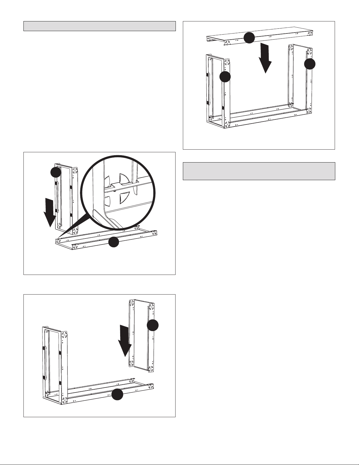
Assembly the Cabinet
The cabinet sections are designed to lock together. Align
the edges as shown in Figure 3 on page 3. It may be
necessary to apply force to snap the tight pieces together.
1. Remove front frame B from door C.
2. Place side panel E on a rm surface. Align and insert
front frame B into one end of side panel E (see fFigure
3 on page 3). Firmly press down until each corner
has snapped into place.
3. Align and insert rear frame A into side panel E (see
Figure 4 on page 3).
4. Align and insert remaining side panel E into front frame
B and rear frame A. Firmly press down until each corner
has snapped into place (see Figure 5 on page 3).
NOTE: Side rails (D) are attached to the cabinet after the
cabinet is installed on the Furnace/Air Handler (see
Figure 13 on page 6).
E
B
Snap front frame B into side panel E. Parts interlock as
shown in detail illustration.
Figure 3. Assemble Front Frame (B) to
Side Panel (E)
E
A
Snap rear frame A into side panel E.
Figure 4. Assemble Rear Frame (A) to
Side Panel (E)
E
B
A
Snap remaining side panel E into front frame B and
rear frame A.
Figure 5. Assemble Remaining Side Panel (E)
Use of Healthy Climate Media Air Cleaner
for Construction Filtration
Healthy Climate Media Air Cleaners may be used for l-
tering heated or cooled air of buildings or structures under
construction if the following conditions are met to ensure
proper operation:
DO NOT USE THE UNIT FOR CONSTRUCTION FILTRA-
TION UNLESS ALL OF THE FOLLOWING CRITERIA
ARE MET:
• Cabinet and furnace or air handler must be in their -
nal location. The vent system must be permanently in-
stalled per these installation instructions.
• Refer to furnace or air handler installation instructions
for any additional construction use criteria. All furnace
or air handler construction use criteria must also be met.
• Supply and return air ducts must be provided and
sealed to the furnace or air handler. Return air must be
terminated outside of the space where the furnace or air
handler is installed.
• Healthy Climate MERV 11 or greater air lters must be
installed in the system and must be regularly inspect-
ed and maintained during construction. Filters must be
changes when operating more than 0.1” WC static pres-
sure over initial static pressure at operating airow.
• Air lters must be replaced upon construction comple-
tion.
FILTER LIFE MAY BE SHORTENED WHEN USED IN
STRUCTURES UNDER CONSTRUCTION. FILTER MUST
BE REPLACED UPON CONSTRUCTION COMPLETION.
EQUIPMENT MAY EXPERIENCE PREMATURE COM-
PONENT FAILURE AS A RESULT OF FAILURE TO FOL-
LOW THE THESE INSTALLATION INSTRUCTIONS.

4
FAILURE TO FOLLOW THIS INSTALLATION INSTRUC-
TIONS VOIDS THE MANUFACTURER’S EQUIPMENT
LIMITED WARRANTY. LENNOX DISCLAIMS ALL LIA-
BILITY IN CONNECTION WITH INSTALLER’S FAILURE
TO FOLLOW THE ABOVE INSTALLATION INSTRUC-
TIONS.
NOTWITHSTANDING THE FOREGOING, INSTALLER IS
RESPONSIBLE FOR CONFIRMING THAT THE USE OF
CONSTRUCTION HEAT OR COOLING IS CONSISTENT
WITH THE POLICIES AND CODES OF ALL REGULAT-
ING ENTITIES.
ALL SUCH POLICIES AND CODES MUST BE ADHERED
TO.
Applications
Up-ow Furnace/Air Handler
Cabinet is installed horizontally beneath the furnace/air
handler. Return air enters from the bottom (see following
gure).
RETURN
DUCT
SUPPLY
DUCT
Figure 6. Up-ow Furnace/Air Handler
Down-ow Furnace/Air Handler
Cabinet is installed horizontally in the return air duct just
bove the furnace/air handler.
RETURN
DUCT
SUPPLY
DUCT
Figure 7. Down-ow Furnace/Air Handler
Up-ow Furnace (up to 4 ton application)
Cabinet is installed vertically and return air enters the fur-
nace side inlet.
RETURN
DUCT
SUPPLY
DUCT
Figure 8. Up-ow Furnace (up to 4 ton)

5
Up-ow Furnace (5-ton application)
Option 1—Install Return air base, part numbers 98M60,
98M58. HCC20-28 Cabinet is installed vertically and return
air enters the furnace side inlet.
RETURN
DUCT
SUPPLY
DUCT
OPTIONAL
RETURN
AIR BASE
Figure 9. Up-ow Furnace (5 ton, Option 1)
Option 2—Over cut top edge of side return opening by 1”
to 15” x 23”. HCC20-28 Cabinet is installed vertically and
return air enters the furnace side inlet.
OVERCUT TOP
EDGE BY 1”
15”
23”
Figure 10. Up-ow Furnace (5 ton, Option 2)
Horizontal Furnace/Air Handler
Cabinet is installed vertically in the return air duct near the
furnace/air handler.
RETURN DUCT
SUPPLY DUCT
Figure 11. Horizontal Furnace/Air Handler
Installation
Cabinet Installation
The following is a typical installation of the cabinet with an
up-ow furnace (see Figure 8 on page 4).
1. Position the cabinet alongside the furnace with the
access door opening facing outward.
2. Align the cabinet opening with the opening on the
furnace. (For 5 ton application, use option 1 or 2 [see
Figure 9 on page 5 and Figure 10 on page 5).
3. Secure the cabinet to the furnace using sheet metal
screws in the pre-drilled cabinet mounting holes (see
gure 12).
4. Use a butt joint to attach the duct to the upstream side
of the cabinet.
NOTE: If necessary, use sheet metal turning vanes to
improve air movement through an elbow in the duct.
5. Connect the next section of the duct. If necessary, use
a properly sized wooden block to support a duct elbow.
6. Use foil tape to seal all duct joints. This prevents dust
from entering the air stream.
7. Insert side rails (D) into the cabinet and use the provided
screws to secure them to the cabinet at both the top and
bottom (see gure 13).
8. Slide the lter into the rail and secure the cabinet door
(see gure 14).
WARNING
Risk of Carbon Monoxide
poisoning.
Can cause injury or death.
Do not operate without Filter
Cabinet door in place. Operation
of this equipment without the
Filter Cabinet door in place may
cause exhaust fumes to be drawn
into occupied spaces.
CABINET
FURNACE
RETURN
DUCT
Figure 12. Attach Cabinet to Furnace and Duct

6
Insert two side rails (D) into cabinet and secure with provided
screws to top and bottom of cabinet.
CABINET
FURNACE
RETURN
DUCT
SIDE
RAILS
Figure 13. Install Side Rails
FILTER
DUCT
DOOR
Figure 14. Insert Filter and Attach Door
This manual suits for next models
2
Table of contents
Other Healthy Climate Solutions Air Cleaner manuals


