Healthy Climate HCWB3 User manual
INDOOR AIR QUALITY
HCWB3
Healthy Climate®
By-Pass Humidier
Bulletin No. 210543
September 2009
Model Number Identification
HCWB 3 - 17 A
Unit Type
HCWB = Healthy Climate By-Pass Humidier
Nominal Capacity
12 = 12 US Gallons per day
17 = 17 US Gallons per day
Features
WARRANTY
All covered components - limited warranty for ve
years in residential applications, one year in non-
residential applications.
Refer to the Lennox Equipment Limited Warranty
certicate included with the unit for additional details.
APPROVALS
Units are UL listed per ANSI/UL 998 and CSA C22.2
No.104-01.
APPLICATIONS
Applicable to most forced air installations.
Installs on the supply air plenum with a by-pass duct
from the return plenum in up-ow and horizontal
applications. Installs on the return air plenum with a
by-pass duct from the supply plenum in down-ow
applications. See Typical Applications.
Provides additional humidity to the home during the
heating season to increase comfort level.
Do not install where freezing may occur.
Humidier, saddle valve and manual or automatic
humidier control (depending on model) shipped in one
package.
Sequence of Operation
Humidier will only operate when indoor blower is
operating.
When the level of moisture in the return air or living
space area drops below the set point of the humidier
control, the water solenoid valve opens, water ows
into distribution tray and weeps down through the
evaporator pad. By-pass air ows over the evaporator
pad, increasing the humidity of the air, and then back
into the return air stream. When the humidier control
is satised the water solenoid valve closes.
Cabinet
Rugged, corrosion resistant molded plastic.
Humidier is shipped for left-hand by-pass duct
connection.
For right-hand by-pass duct connection, rotate
humidier cabinet 180º top for bottom and relocate
drain spud. See Installation Instructions for additional
details.
Built-in damper included to close off bypass duct during
summer cooling operation.
ENGINEERING DATA
Series
Controls
(blank) - Manual Humidistat
A = Automatic Humidier Control
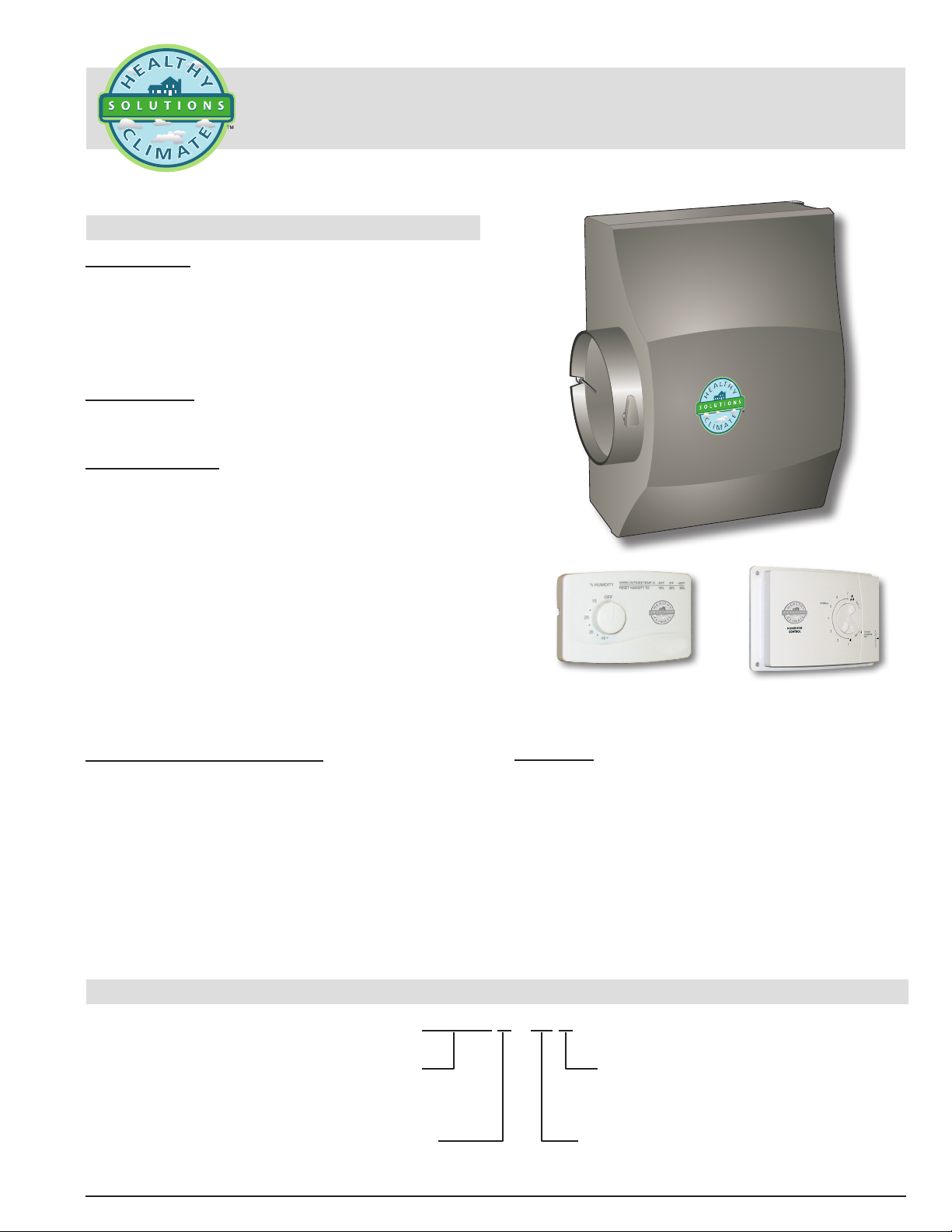
Automatic Humidier Control
(furnished with “A” Models)
Manual Humidistat
(furnished with
standard Models)

HCWB3 − By-Pass Humidier / / Page 2
FEATURES
CONTROLS
Manual Humidistat - HCWB3-12 and HCWB3-17
Can be horizontally mounted on wall or duct.
Provides manual control of room relative humidity.
Wired in series with the humidier water solenoid
valve.
Adjustable setting.
Automatic Humidier Control - HCWB3-12A and
HCWB3-17A
Wall or duct mounted.
Automatic or manual mode control. Manual Mode label
(with resistor to bypass outdoor temperature sensor)
are furnished to indicate when humidistat is installed in
Manual Mode.
Senses indoor relative humidity and outdoor
temperature. Includes outdoor temperature sensor
for use with automatic control option and resistor for
manual control setting.
Adjusts humidity setpoint to provide optimum humidity
levels within the space.
Adjustable setting.
WATER SUPPLY
Consists of supply tubing, orice, distribution tray,
cleanable/replaceable internal strainer and 24 volt
brass water solenoid valve with stainless steel seat.
Drain
1/2 in. drain tting at bottom of cabinet.
1/2 in. ID plastic tubing must be eld provided.
Unused water from the evaporator pad is drained from
the unit to help remove mineral deposits left from the
evaporative process.
Distribution Tray
Reservoir and unique polyester liner provides even
water distribution across the evaporator media pad for
optimal performance.
Tray and support frame removable for cleaning or
replacement.
Evaporator Media Pad
Provides large evaporation capacity.
Pad and support frame removable for cleaning or
replacement.
Annual pad replacement recommended.
Saddle Valve
All necessary ttings furnished as standard equipment.
Field installs in the water supply line
OPTIONAL ACCESSORIES
Installation Kit (Canada Only)
Kit contains: 6 in. dia. duct ring ange, 2.5 ft. of 6
in. dia. galvanized steel exible duct, 10 ft. of 1/4 in.
OD polyethylene water feed tube, 15 ft. of 1/2 in.
ID clear nylon drain tube, 10 ft. of 2-conductor 18
AWG thermostat wire, one hose clamp, two plastic
compression sleeves, and two plastic compression
ferrules.
MAINTENANCE SUPPLIES
Replacement Media
Recommended annual replacement of media pad.
See Specications table for catalog number.
SPECIFICATIONS
Model No. With Manual Humidistat Control HCWB3-12 HCWB3-17
With Automatic Humidier Control HCWB3-12A HCWB3-17A
Capacity - 120°F plenum temperature, 0.20 in. w.c. static pressure drop 12 US gallons per day 17 US gallons per day
Water Feed Rate (gallons per hour @ 50 PSI water pressure) 3 3
Evaporator pad size - H x W x D - in. 9-1/2 x 9-5/8 x 1-11/16 13 x 10 x 1-11/16
Connections Plenum H x W - in. 9-1/2 x 9-1/2 12-3/4 x 10
By-Pass Duct - in. 6 round 6 round
Water supply 1/4 in. compression 1/4 in. compression
Drain 1/2 in. I.D. 1/2 in. I.D.
Electrical characteristics 24V 24V
Shipping Data - lbs. (1 package) 8 9
MAINTENANCE SUPPLIES - MUST BE ORDERED EXTRA
Replacement Media X2660 X2661
OPTIONAL ACCESSORIES - MUST BE ORDERED EXTRA
Installation Kit (Canada Only) 21N85 21N85
HCWB3 − By-Pass Humidier / Page 3
TYPICAL APPLICATIONS
HUMIDIFIER
HORIZONTAL UNIT
SUPPLY
AIR
RETURN
AIR
UP−FLOW UNIT
HUMIDIFIER
RETURN
AIR
SUPPLY
AIR
DOWN−FLOW UNIT
RETURN
AIR
SUPPLY
AIR
HUMIDIFIER
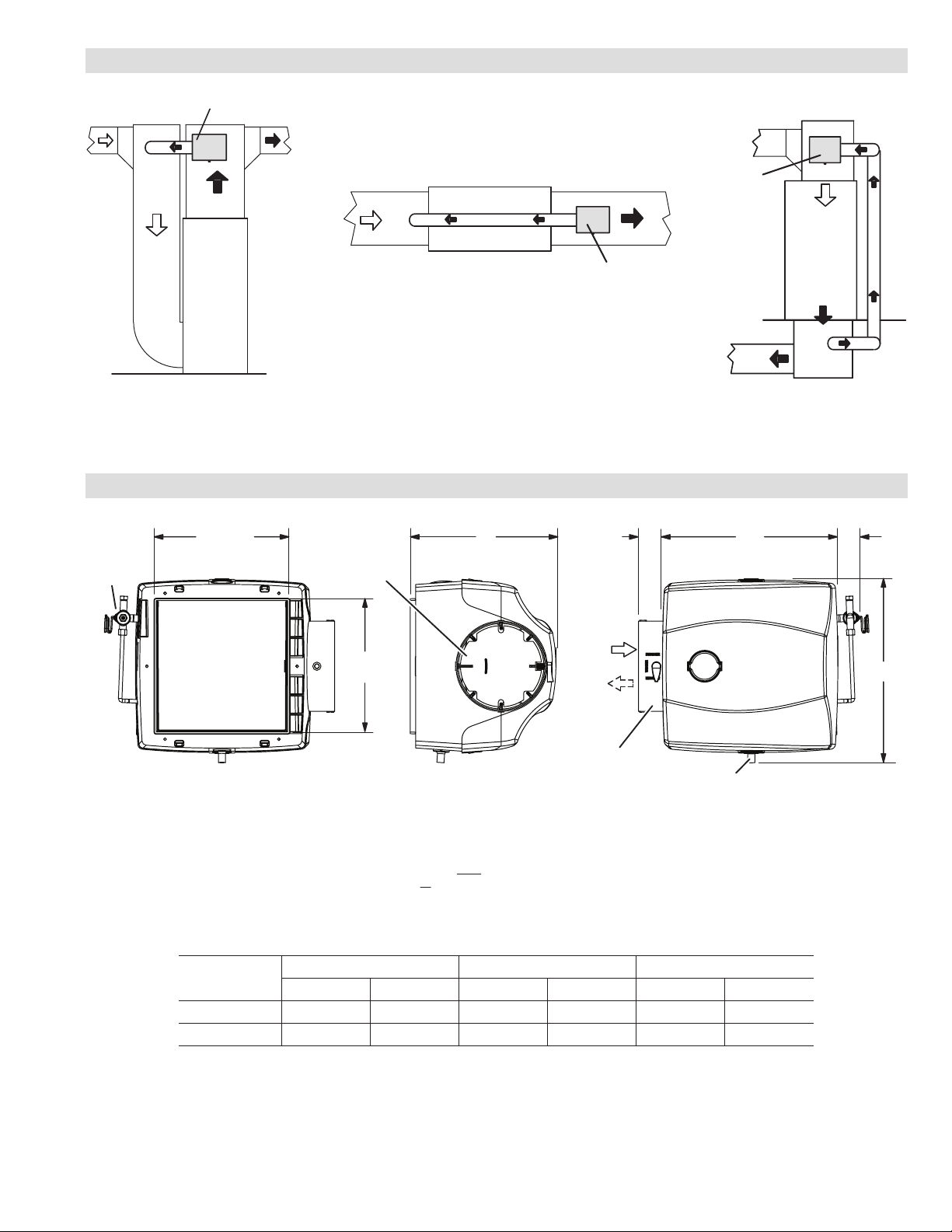
DIMENSIONS - INCHES (MM)
− For upflow/horizontal applications air flow is from the humidifer to return air duct.
FRONT VIEWLEFT SIDE VIEWBACK VIEW
9-1/2 (241)
OPENING
12
(305)
1-1/2
(38)
1-3/4
(44)
A
6-1/8 (156) DIA.
BY−PASS DUCT
CONNECTION
B
OPENING
1
AIR FLOW
NOTES:
By-pass duct air flow direction is dependent on application.
− For downflow applications, air-flow is to the humidifier from the supply air duct.
1Left hand air inlet/outlet shown. For right-hand inlet/outlet, rotate humidifier cabinet 180º top for bottom and relocate
drain to alternate location on cabinet. See Installation Instructions for additional details.
DRAIN
SOLENOID
VALVE
SUMMER / WINTER
DAMPER CONTROL
C
Model No. A B C
in. mm in. mm in. mm
HCWB3-12(A) 12-7/8 327 9-1/2 241 10-1/4 260
HCWB3-17(A) 15-7/8 403 12-3/4 324 10-1/2 267

NOTE - Due to Lennox’ ongoing commitment to quality, Specications, Ratings and Dimensions subject to change without notice and without incurring liability.
Improper installation, adjustment, alteration, service or maintenance can cause property damage or personal injury.
Installation and service must be performed by a qualied installer and servicing agency. ©2009 Lennox Industries, Inc.
Visit us at www.lennox.com
For the latest technical information, www.lennoxdavenet.com
Contact us at 1-800-4-LENNOX
HUMIDIFIER SIZING iNFORMATION
(BASED ON VOLUME OF HOME)
Model No. Type of Home 8 Foot Ceiling 9 Foot Ceiling 10 Foot Ceiling
Home Area (sq. ft.) Home Area (sq. ft.) Home Area (sq. ft.)
HCWB3-12,
HCWB3-12A
Loose 750 666 600
Average 1500 1350 1200
Tight 3000 2700 2400
HCWB3-17,
HCWB3-17A
Loose 1000 888 800
Average 2000 1800 1600
Tight 4000 3600 3200
NOTES:
Loose Home = Two Air Change Rates per hour: Typically, loose in construction and is over 20 years old. Not very well insulated and may
have single pane windows, etc.
Average Home = One Air Change Rate per hour: Average in construction, 15 to 20 years old on average.
Tight Home = One-Half Air Change Rate per hour: Newer home with tight construction..
Also see Healthy Climate Power Humidifer HCWP3 bulletin for additional sizing conditions if needed.
Table of contents
Other Healthy Climate Humidifier manuals


Popular Humidifier manuals by other brands

Beurer
Beurer maremed MK 500 Instructions for use

Aprilaire
Aprilaire 800 Series Installation & maintenance instructions

DH Lifelabs
DH Lifelabs Aaira + Humidifier quick start guide

DriSteem
DriSteem SINGLE-TUBE Series Installation, operation and maintenance manual

American Red Cross
American Red Cross Y7087 Cool Mist Humidifier user guide

HygroMatik
HygroMatik DDS manual


