HE&M A-1 AIR SAW Instruction Manual
1
OPERATION
A-1 AIR SAW

2
OPERATIONS
Lock-Out/Tag-Out Procedure
This document outlines the process for Lock-Out/Tag-Out for an Air Saw.
While there are some variations from model to model with the high voltage junction box
appearance the function will be the same. It is important to follow all safety practices and pay
attention to all safety warnings noted in this procedure. Always de-energize the machine before
performing any maintenance. Failure to do this may result in serious personal injury.
Hazard Identification
De-Energize and use Lock-Out/Tag-Out procedures when performing maintenance
activities.
1. Move the “POWER”
switch to the “OFF”
position.

3
3. De-Energize the saw by pushing the Main Disconnect
Handle down to the “OFF” position.
4. Perform the LOCK-OUT/TAG-OUT procedure
using a lock plate and a LOTO padlock. This will
prevent anyone from turning power back onto the saw
during service and maintenance.
2. The High Voltage Junction Box will be located on
the side or back of the saw and is equipped with a
Main Disconnect that has the ability to accept a
padlock for electrical Lock-Out/Tag-Out.

4
HOW TO ENERGIZE THE SAW
2. Verify that the “Emergency Stop” button located on the top of the
control console is raised up in the off position. (If it is pressed down, turn
the button clockwise to raise it.)
4. To Energize the Control Panel, move the spring-loaded
“START” switch to the “START” position. Move it up and
allow it to spring back down to the “ON” position. Power to
the Control Panel will be noted by the illuminating “POWER
ON” indicator light.
1. Pull the Main Disconnect lever located on the High Voltage
Junction Box to the “ON” position to energize the saw.
ON
3. Verify that all of the switches on the Control
Panel are in the “NEUTRAL” or center
position.
NOTE: This is a safety feature; the saw will
not start if certain switches are not in the
correct position.

5
MOTOR RESET
How to De-Energize the Control
The control circuit must be de-energized in a particular way if it is to remain de-energized for an
extended period of time, (over two hours). This will allow the saw to rest and not drift from
square or put strain on the components.
1. The material being cut should be removed from the blade’s path.
2. After the material has been removed from the blade’s path, the operator can lower the arm into
the cutting block by pressing the ARM “CUT” button.
3. After lowering the arm move the POWER switch to the “OFF” position.
NOTICE: The saw must be allowed to complete the cut through the material it is cutting or
the arm must be raised completely out of the material before the saw is de-energized. If the
saw is de-energized with the blade in the cut it may cause irreparable damage to the blade or
damage the saw which might not be covered by warranty.
MOTOR RESET BUTTON
If the saw appears to have power but the motor won’t
start, it could be the “MOTOR RESET BUTTON” has
tripped off. This button acts like a circuit breaker. To
reactivate it, tap the blue “MOTOR RESET BUTTON”
several times. The “MOTOR RESET BUTTON” may be
located in the saw Electrical Box or in the Main
Disconnect Box.

6
MANUAL CUT
2. Adjust the arm height with the upper arm stop to have it close enough to the material so that
the arm does not have too much free-fall before starting the cut. The Feed Rate and Cutting
Pressure should also be correctly set for the material to be cut. For more information on setting
the Arm Height, Feed Rate, and Cutting Pressure refer to the “ARM HEIGHT STOP” and
“FEED RATE and CUTTING PRESSURE” section in this manual. Place the material in the vise
making sure it is laying flat on the vise ways and in the cutting area. Support longer material
with additional stock roller tables.
3. Move the “CLAMP” switch downward to the “CLOSE”
position. Always check the vise pressure to determine that it is
sufficient to hold the part, but not high enough to deform smaller
sections or thinner walled material.
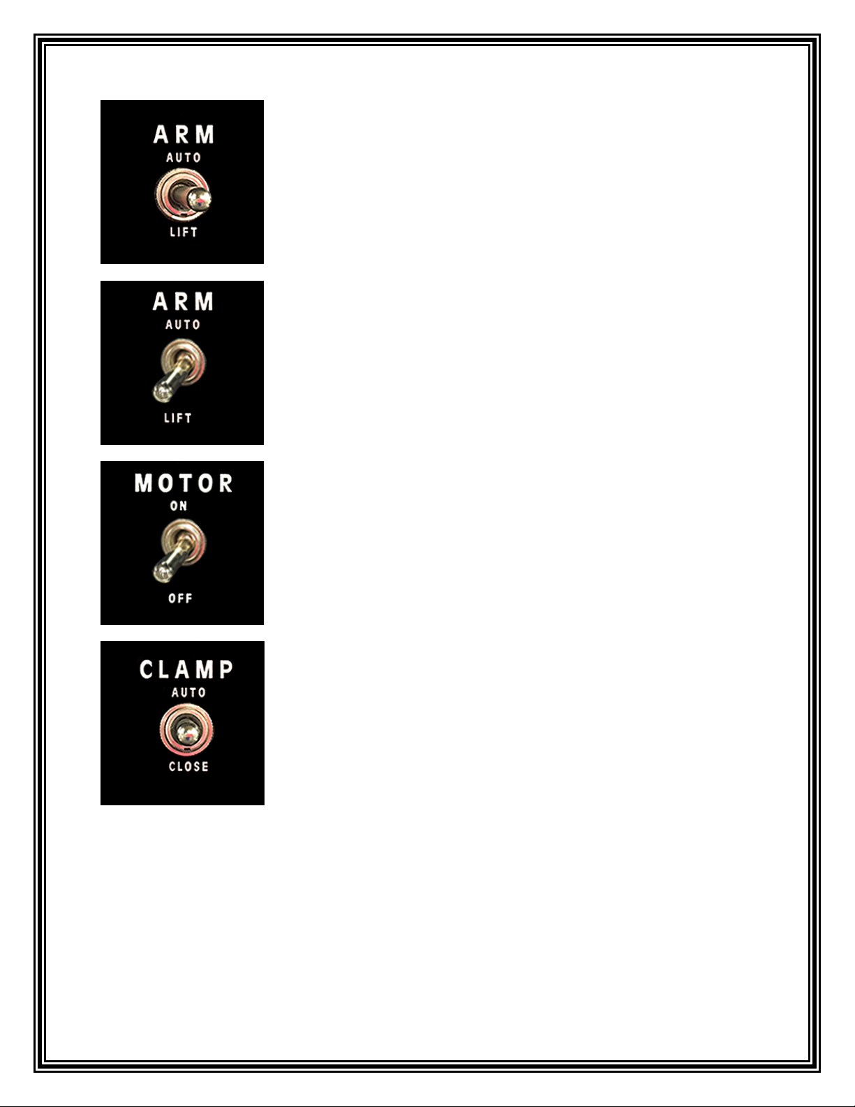
1. To make a manual cut, lift the arm by moving the “ARM”
switch down to the “LIFT” position.
7
4. For a trim cut, place the end of the material far enough past the blade to trim the material as
needed. For a predetermined length part, mark the material at the correct length and place the
material so that the mark is aligned with the path of the blade.
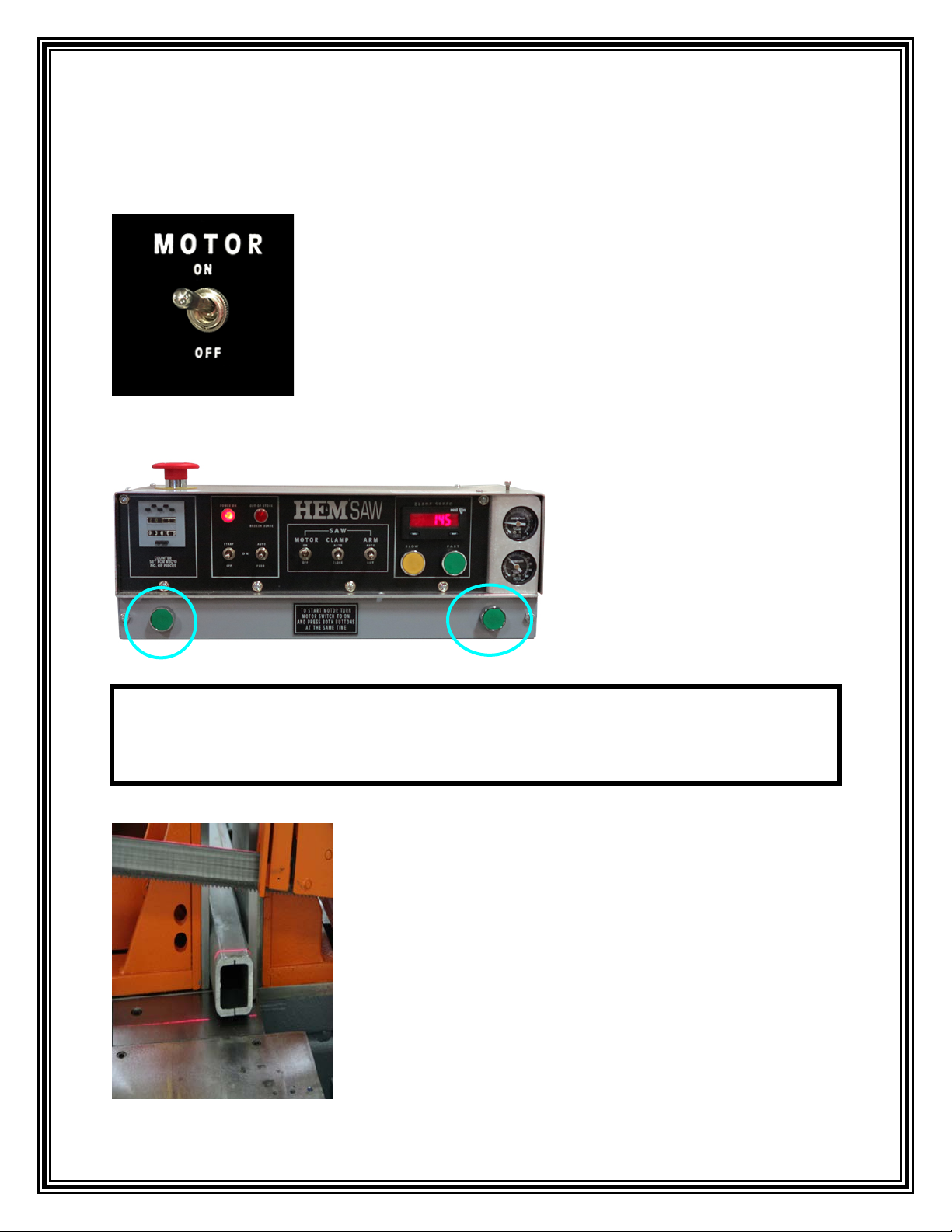
5. Once the material is securely clamped in the vise and the arm
is set to the appropriate height, start the motor by moving the
“MOTOR” switch up, to the “ON” position.
6. When the motor starts, be sure the blade speed is
adjusted correctly for the material being cut.
NOTE SIDEWINDER MODELS ONLY: Start the motor by moving the “MOTOR”
switch up, to the “ON” position and, then using two hands press the two “GREEN SAFETY
START BUTTONS” at the same time.
8
7. To initiate the cut, put the “ARM” switch in the center
“neutral” position. This will allow the arm to fall at the set
Feed Rate and start the cut at the set Cutting Pressure.
8. When the blade completes the cut, move the “ARM”
switch down to the “LIFT” position.
10. To remove the material from the closed vise, move the
“CLAMP” switch to the center “neutral” position. Be sure
the material is supported if it is too long to be supported by
the vise-way and/or by the discharge table.
9. Move the “MOTOR” switch down to the “OFF” position.

9
AUTOMATIC CUTTING SEQUENCE
If multiple parts of the same length are required, the saw will be operated with an automatic
cutting sequence in automatic mode.
Place the material on the saw, with longer length material properly supported, and align it for
either a trim cut or flush with the blade if not trim cut is required.
After the desired part length has been set in the DRO at the rear of the saw (Refer to the section
“Setting the Part Length” of this manual for information on setting the DRO), set the Part
Counter for the quantity of parts desired. Make sure the Parts Cut has been cleared (the bottom
row of numbers is cleared by pressing the big black button below the numbers) before starting
the automatic sequence.
The Automatic Sequence is ready to be started. If a trim cut is required and the material is
positioned past the blade at the appropriate distance, start the trim cut sequence by putting the
“CLAMP” switch in the “CLOSE” position. Put the “AUTO” switch in the top “AUTO” position
(this will move the shuttle back for the first part after the trim cut).
Start the motor by moving the “MOTOR” switch into the “ON” position, then press both green
buttons at the same time (For SidewinderA-1 Only). The motor will start and the blade will turn.
Be sure the Blade Speed is set correctly for the type of material being cut and that the Feed Rate
and Cutting Pressure are also set properly.
Move the “ARM” switch to the center or “NEUTRAL” position. This will allow the arm to fall,
cutting the trim part. When the arm completes the cut, and starting from right to left, move all the
switches up to the “AUTO” position (the “AUTO” switch was already positioned there), and
press the spring-loaded “START” switch up. The arm will raise, the saw clamp will open, the
feed clamp will close, the feed shuttle will move forward to the length set in the DRO, the saw
clamp will close and the arm will begin to fall, cutting the first part. After the saw vise closes and
the arm begins to fall, the feed will retract to position for the next part index.
Other manuals for A-1 AIR SAW
1
Table of contents
Other HE&M Control Panel manuals

Popular Control Panel manuals by other brands


SLEIPNER MOTOR AS
SLEIPNER MOTOR AS SIDE-POWER PJC-322 Installation and user manual

Fagor
Fagor Innova 40i TS Installation & operation manual

DeDietrich
DeDietrich IniControl 2 Troubleshooting

Klimosz
Klimosz HoGas duo instruction manual

Bender
Bender COMTRAXX CP9 Series manual

Extron electronics
Extron electronics MLC 55 RS user guide


