Hearth and Home Technologies Heat Recovery Ventilator HRV200PLUS User manual

02/04 4034-102 Rev F 1
CAUTION:
Do not expose the appliance to the elements (such
as rain, etc.).
IMPORTANT!
Before installation, the installer must give careful consider-
ation to how this HRV 00PLUS system will operate if con-
nected to any other piece of mechanical air movement equip-
ment, i.e. a forced air furnace or air handler, operating at a
higher or lower static pressure.
Before the installation, the installer must assess any inter-
action between the HRV 00PLUS and vented combustion
equipment, i.e. gas furnaces, oil furnaces, wood stoves, etc.,
and ensure the ability of the vented appliances to properly
vent is not compromised by the operation of the
HRV 00PLUS system.
After installation, the installer must confirm the compatibil-
ity of the installed system by measuring both air flows of
the HRV 00PLUS by using the balancing procedure found
in this manual and evaluating the effects on any intercon-
nected equipment.
NEVER install a ventilator in a situation where its normal
operation, lack of operation or partial failure may result in
the back drafting or improper functioning of vented com-
bustion equipment!!!
For assistance during installation contact your local dealer
or contact the Heatilator Technical Services Depart ent,
Hearth & Ho e Technologies Inc., 1915 W. Saunders Street,
Mt. Pleasant, Iowa 52641, 1-877-IAQ-VENT
(1-877-427-8368).
HEATILATOR® is a registered trade ark of Hearth & Ho e
Technologies Inc.
INSTALLATION & OPERATING
INSTRUCTIONS
PLEASE RETAIN THIS MANUAL
FOR FUTURE REFERENCE
This appliance is certified to CSA . and UL181 standards
and also is perfor ance tested to CSA439-00.
HRV200PLUS
HEAT RECOVERY VENTILATOR
DESIGNED TO OPERATE WITH THE FOLLOWING FRESH AIR FIREPLACES:
HEATILATOR CNXT70IPLUS SERIES & NB4236IPLUS SERIES
HEAT-N-GLO 6000PLUS SERIES & 6100PLUS SERIES
Note: The Caliber NXT Plus gas appliance (CNXT70IPLUS Series)
and the 6100 PLUS (6100PLUS Series) CANNOT be installed at an
elevation above 6,200 ft. (1,890 ).
Note: An arrow (Æ) found in the text signifies change in
content.
Æ
Æ
Æ

2 4034-102 Rev F 02/04
HRV200PLUS INSTALLATION INSTRUCTIONS
The Heatilator Ho e Products Heat Recovery Ventilator 200 Plus (HRV200PLUS) works as a power ventilator for the Fresh Air Fireplaces
(FAF) fro Heatilator and Heat-N-Glo, and is designed to provide fresh air into a building while exhausting an equal a ount of stale air.
This balanced operation ensures opti u perfor ance with no effect on the relative pressurization of the structure. During winter
onths when the indoor space is heated, the heat recovered fro the fireplace exhaust heats the inco ing fresh air as both air strea s
pass through the heat recovery core. During su er onths when the indoor space is air conditioned, the stale indoor air re oves
heat fro the heat recovery core to cool the inco ing fresh air.
The Heatilator Ho e Products Heat Recovery Ventilator Plus allows your ho e to breathe, expelling fireplace exhaust, stale air and
airborne pollutants and providing a constant supply of healthy, fresh air.
The HRV200PLUS is certified by HVI as a stand alone ventilator and is certified by UL as part of the Fresh Air Fireplace heat recovery
syste .
A. INTRODUCTION
B. HRV200PLUS APPLICATION
Selecting the proper equip ent for the cli ate is essential for aintaining co fort levels and axi izing efficient operating conditions.
In general, the following guidelines apply:
1. The HRV200PLUS is designed for cli ates where the heating season is typically longer than the cooling season. The HRV is
equipped with an alu inu core not allowing the transfer of oisture between the air strea s
. The HRV200PLUS is suitable for use in cli ates where the outdoor te perature drops below 25°F (-4°C) for ore than five
days.
The reference ap on the following page highlights geographic areas for HRV/ERV applications. ERV (Energy Recovery Ventilator)
appliances allow oisture to transfer across the core and are appropriate for very high hu idity geographies. An ERV application for
the Fresh Air Fireplace is NOT available.
WARNING!
The HRV 00PLUS is designed specifically to work with the Fresh Air Fireplaces from Heatilator. DO NOT attempt to hook
up the HRV 00PLUS to other gas fireplaces or to wood burning fireplaces. The Fresh Air Fireplace MUST be installed in
conjunction with the HRV 00PLUS in order for it to vent properly. DO NOT ATTEMPT TO ACHIEVE THIS CONFIGURATION
WITH ANY OTHER FIREPLACE.
Fresh Air Fireplaces are identified by the PLUS suffix in the model number/nomenclature (i.e. CNXT70IPLUS).
TABLE OF CONTENTS
A. Introduction .......................................................................................................................................................................................... 2
B. HRV200PLUS Application ................................................................................................................................................................... 2
C. Engineering Data ................................................................................................................................................................................. 3
D. Defrost Options ................................................................................................................................................................................... 5
E. Installation Diagra s .......................................................................................................................................................................... 7
F. Installing the Ventilator ...................................................................................................................................................................... 10
G. Vent and Duct Installation ................................................................................................................................................................. 11
H. Exhaust Ter ination .......................................................................................................................................................................... 16
I. Selecting Blower Speeds .................................................................................................................................................................. 24
J. Balancing ........................................................................................................................................................................................... 25
K. Operating Modes ............................................................................................................................................................................... 29
L. Wiring ................................................................................................................................................................................................ 34
M. Maintenance Instructions .................................................................................................................................................................. 39
N. LED Diagnostics ................................................................................................................................................................................ 41
O. Troubleshooting Guide ...................................................................................................................................................................... 42
P. Accessories ....................................................................................................................................................................................... 45
Q. Replace ent Parts ............................................................................................................................................................................ 46
Index .................................................................................................................................................................................................. 47
Li ited Warranty ............................................................................................................................................................................... 48
Æ

02/04 4034-102 Rev F 3
HRV200PLUS INSTALLATION INSTRUCTIONS
C. ENGINEERING DATA
Efficient, Patented Aluminum Core
The cross-flow heat recovery core transfers heat between the intake and exhaust airstrea s. The core re oves easily for cleaning
or service.
Dia nostic LED
A diagnostic LED ounted on the side of the HRV200PLUS cabinet indicates nor al and abnor al operating odes for efficient
syste evaluation without having to open the door.
Supply and Exhaust Air Blowers
The supply and exhaust air flows are supplied by two forward curved blower wheels driven by a co on, double shaft PSC blower
otor. Four field selectable blower speeds one high speed and three low speeds are available to eet specific installation
needs. The blower otor is rated at 120VAC, 1.4 A ps.
Air Filters
Air filters are supplied in both the exhaust and supply air strea s. The filters are washable and easily re oved for cleaning.
Automatic Defrost System
The HRV200PLUS is equipped with an auto atic defrost feature utilizing heat fro the Fresh Air Fireplace to defrost the HRV core.
As a warning feature, the electric e ber bed will light for 15 seconds prior to ignition. Alternatively, a field installed defrost syste
using recirculated indoor air to re ove frost is available as an option.
Cabinet
Painted twenty gauge galvanized steel outer shell and alu inized inner liner sandwich ¾ (19 ) insulation to provide strength,
reduce heat loss and insure a corrosion free life.
Mountin
The HRV200PLUS co es supplied with four reinforced polyester straps which attach to the threaded inserts at each corner of the
case for easy installation and quiet operation.
Installed Weight - 78 lbs. (35.4 kg) Shipping Weight - 84 lbs. (38 kg)

4 4034-102 Rev F 02/04
HRV200PLUS INSTALLATION INSTRUCTIONS
Appliance Dimensions
ecnamrofrePSULP002VRH
DEIFITRECIVH
yrevoceRerutarepmeTmumixaM%07
ssenevitceffEelbisneS
)M934CSC()s/L07(mfc941@
%06
ycneiciffEelbisneS
)C°0(F°23)s/L07(mfc941@
%55
ycneiciffEelbisneS
)C°52-(F°31-)s/L26(mfc131@
%35
zH06@CV021
)deepSwoL(STTW78
)deepShgiH(STTW461
gnitaRpm 4.1
selbitsubmoCotecnaraelCSULP002VRH
ecafruSpoTsediStnorFmottoBkcaB
ecnaraelC"1"1"1"1"0

02/04 4034-102 Rev F 5
HRV200PLUS INSTALLATION INSTRUCTIONS
D. DEFROST OPTIONS
The HRV200PLUS perfor s as a whole house heat recovery ventilator during Fresh Air Fireplace operation and continuous ventilation
operation. When the Fresh Air Fireplace is in use, the HRV core te perature is elevated with no chance of frost or ice build-up at any
ti e. However, when the HRV200PLUS is operating in continuous ventilation ode, outdoor te peratures below 25°F can cause frost
to for on the core. This frost can reduce airflow through the HRV resulting in unbalanced operation and could inhibit Fresh Air
Fireplace operation.
The Caliber NXT Plus and 6100 PLUS Fresh Air Fireplace is an open hearth design using the draft created by the HRV200PLUS to
for an air curtain containing flue products in the hearth, as opposed to the typical glass front. The fronts for the Caliber NXT Plus and
6100 PLUS are shipped with fixed esh screens to provide a barrier between the occupants and the fire.
Choose the defrost method best for your application:
No Defrost
Mild climates where defrost is not needed. Allows fixed mesh screens/screen door retainers to be removed on the Caliber NXT
Plus and the 61 PLUS.
Room Air Defrost
Defrosts with indoor air using the Optional Defrost Kit. Does not cause unexpected Fresh Air Fireplace ignitions. Allows fixed
mesh screens/screen door retainers to be removed on the Caliber NXT Plus and the 61 PLUS.
Fresh Air Fireplace Defrost
Defrosts with the heat from the Fresh Air Fireplace. Causes unexpected Fresh Air Fireplace ignitions. Fixed mesh screens/
screen door retainers must be used on the Caliber NXT Plus and the 61 PLUS.
WARNING!
Removing the DEFC1 jumper allows the HRV 00PLUS to independently ignite the Fresh Air Fireplace.
WARNING!
Do not remove the fixed mesh screen or screen door retainers on the Caliber NXT Plus and the 6100 PLUS fronts unless:
1. Fresh Air Fireplace Defrost is disabled (DEFC1 jumper installed), and
. Fresh Air Fireplace operation is supervised by an adult. Removing the fixed screen mesh or mesh door retainers could
result in injury, property damage or death.
Note: When No Defrost or Roo Air Defrost is selected for the defrost ethod, the fireplace will not be used for defrost cycles. So e
ho eowners ay elect to re ove the fixed esh screen or screen door retainers fro the Caliber NXT Plus and the 6100 PLUS fronts for
true open hearth operation.
1. No Defrost
This option is not generally reco ended but ay be used under the following conditions:
a. The syste is installed in an area with fewer than five days a year with an outside te perature below 25°F. These areas are
typically in the southern and coastal regions of the country.
b. The syste will not be used for continuous ventilation. This application is for the installation where the HRV200PLUS is not the
pri ary ventilation eans for the building and will only be used as a power vent/heat recovery device for the Fresh Air
Fireplace.
c. Setup for No Defrost Option
1) Install the HRV200PLUS and the Fresh Air Fireplace per the instructions in this anual.
) Ensure the DEFC1 ju per is installed on the HRV control board. This ju per will disable the defrost logic in the
HRV200PLUS.
Æ
Æ
Æ
Æ
Æ

6 4034-102 Rev F 02/04
HRV200PLUS INSTALLATION INSTRUCTIONS
2. Room Air Defrost
a. When the HRV200PLUS syste is installed in cli ates that nor ally have ore than five days a year with an outside te perature
below 25°F, Roo Air Defrost is the reco ended defrost ethod for two reasons:
1) Unanticipated fireplace ignition due to the HRV200PLUS entering the defrost cycle is eli inated, and
) This presents the opportunity for so e ho eowners to re ove the fixed esh screen or screen door retainers on the front
of the Caliber NXT Plus or the 6100 PLUS allowing true open hearth operation.
b. Setup for Room Air Defrost Option
1) Install the HRV200PLUS and the Fresh Air Fireplace per the instructions in this anual.
) Install the Optional Defrost Kit (part # HRV99DEFKIT). The Optional Defrost Asse bly is icroprocessor controlled to
efficiently perfor all defrost functions independently of the HRV200PLUS.
3) Ensure the DEFC1 ju per is installed on the HRV control board. This ju per will disable the defrost logic in the
HRV200PLUS.
3. Fresh Air Fireplace Defrost
When the HRV200PLUS syste is installed in cli ates that nor ally have ore than five days a year with outside te peratures
below 25°F, Fresh Air Fireplace Defrost is a desirable defrost ethod because it utilizes the heat fro the Fresh Air Fireplace to
clear any frost build-up on the heat recovery core. However, the following precautions should be noted:
a. This method does allow the HRV 00PLUS to independently ignite the Fresh Air Fireplace which may result in unexpected
fireplace operation.
b. The fixed esh screen or screen door retainers on the Caliber NXT Plus and the 6100 PLUS fronts ust not be re oved
when using the Fresh Air Fireplace Defrost option.
c. Setup for Fresh Air Fireplace Defrost Option
1) Install the HRV200PLUS and the Fresh Air Fireplace per the instructions in this anual.
) Re ove the DEFC12 ju per on the HRV control board. Re oving this ju per will allow the HRV200PLUS to control the
Fresh Air Fireplace for defrost cycles.
Æ
Æ

02/04 4034-102 Rev F 7
HRV200PLUS INSTALLATION INSTRUCTIONS
E. INSTALLATION DIAGRAMS
Note: Mini u and axi u clearances ust be aintained at all ti es. Illustrations throughout these instructions reflect
typical installations and are for design purposes only. Actual installation ay vary slightly due to individual design preferences.
The illustrations and diagra s used throughout these installation instructions are not drawn to scale.
1. Simplified Installation (Supply/Return Method)
HRV ust be balanced.
It is reco ended that the furnace blower run continuously or HRV operation be
interlocked with the furnace blower (refer to Section L. Wiring).
Check local codes/authority having jurisdiction for acceptance.

8 4034-102 Rev F 02/04
HRV200PLUS INSTALLATION INSTRUCTIONS
X
b. Fresh Air
Fresh air supplied to ain living areas of
the ho e (bedroo , fa ily roo ).
Stale air drawn fro furnace return.
HRV ust be balanced.
2. Partially Dedicated Installation
a. Exhaust Air
Stale air drawn fro key areas of the ho e (bathroo ,
kitchen, laundry).
Fresh air supplied to supply air duct of furnace.
HRV ust be balanced.

02/04 4034-102 Rev F 9
HRV200PLUS INSTALLATION INSTRUCTIONS
x
3. Fully Dedicated Installation
Stale air drawn fro key areas of the ho e (bathroo ,
kitchen, laundry).
Fresh air supplied to ain living areas.
HRV ust be balanced.

10 4034-102 Rev F 02/04
HRV200PLUS INSTALLATION INSTRUCTIONS
1. Location
The HRV200PLUS ust be located in a heated space where it will be possible to conveniently service the ventilator. Typically the
HRV200PLUS would be located in the echanical roo or an area close to the outside wall where the weather hoods will be
ounted. If a base ent area is not convenient, a utility or laundry roo ay be used.
Attic installations are not nor ally reco ended due to:
a. The co plexity of work to install.
b. Freezing conditions in the attic.
c. Difficulty of access for service and cleaning.
Sufficient clearance at the front of the access door is required for servicing the air filters and core. A ini u of 25 (635 )
clearance is reco ended so the door can be opened. Four PVC reinforced polyester hanging straps are provided for hanging the
HRV200PLUS fro the base ent floor joists.
2. Mountin
The hanging straps should be attached to the ventilator at the top end corners ( ounting screws are already located on the
ventilator case). Securely fasten the other end of the straps to the floor joists with wide head nails (not supplied), aking sure the
ventilator is level. The straps are designed to reduce the chance of noise, resonance or har onics; therefore using the full length
of the strap between the HRV200PLUS and the floor joists is reco ended.
F. INSTALLING THE VENTILATOR
WARNING!
In order to prevent electric shock when cleaning or servicing the HRV 00PLUS, it is extremely important to confirm the
polarity of the power line that is switched by the safety (disconnect) switch. The hot line (black) is the proper line to be
switched. To confirm the proper polarity, use a voltmeter or test lamp to ensure there is no power after the switch when the
door is open. Check between that point and ground (on the cabinet). This must be done as dwellings are occasionally
wired improperly. Always make sure that the HRV 00PLUS is properly grounded.
3. Electrical
The HRV200PLUS should be plugged into a standard designated (120VAC) electrical outlet with ground. The HRV200PLUS is
equipped with a 3 foot electrical cord so it should be located within 3 feet fro electrical service. It is not reco ended that an
extension cord be used for this appliance. If further wiring is required, then a licensed electrician should ake all electrical connections.
It is reco ended that a separate 15 a p/120 volt circuit be used.
4. Installin the Drain Line and P-Trap
When defrosting, the HRV200PLUS ay produce so e condensation. This water should flow into a nearby drain or be taken away
by a condensate pu p. The ventilator and all condensate lines ust be installed in a space where the te perature is aintained
above the freezing point.
Figure 1
WARNING!
Improperly installed water drain lines could result in property dam-
age.
Construct a P-Trap using the plastic tee connector. Cut two lengths of
hose and connect each piece to an end of the T fitting, then connect
the other ends to the two drain spouts. Allow the T fitting to point
upwards. Connect to the drain line. Tape or fasten the base to avoid
any kinks. This creates a trap which will hold so e condensate and
prevent odors fro being drawn up the hose and into the fresh air supply
of the HRV200PLUS. See Figure 1.

02/04 4034-102 Rev F 11
HRV200PLUS INSTALLATION INSTRUCTIONS
G. VENT AND DUCT INSTALLATION
The HRV200PLUS (HRV) not only serves as the fresh air ventilator for the ho e, but is also the power venting device for the Fresh Air
Fireplace (FAF). The conduits fro the FAF to the HRV and fro the HRV to the exhaust ter ination re ove both stale air fro the
ho e and the products of co bustion fro the FAF. Thus the exhaust air conduit acts as the chi ney for your fireplace!
The HRV200PLUS requires four standard and one optional vent/duct connections:
Standard
1. Fresh Air Supply - Fresh air fro the Fresh Air Inlet to the HRV.
. Warmside Air Supply - Heated fresh air fro the HRV into the living area.
3. Fresh Air Fireplace Exhaust - Stale air/co bustion products fro the FAF to the HRV.
4. HRV Exhaust - Stale air/co bustion products fro the HRV to the Flue Exhaust.
Optional - Alternate Exhaust Damper Assembly
Alternate Exhaust - Stale air fro the living area to the HRV.
1. Fresh Air From the Outdoor Intake to the HRV (Fresh Air Supply)
Duct Materials: Fresh Air Inlet - 6 Outside Weatherhood (Part #HRV99189)
Insulated Air Duct - rigid or flexible
CoolVent Flexible Pipe ay be used.
a. Locate the Fresh Air Inlet
See Figure 7 for ore detailed instructions.
Must take air directly fro outdoors.
Should be located upstrea (if there are prevailing winds) fro the exhaust outlet.
At least 3 (.9 ) below when within 10 (3 ) of the exhaust weatherhood, dryer vents or furnace exhaust
( ediu or high efficiency furnaces).
A ini u of at least 10 (3 ) fro driveways, oil fill pipes, gas eters, garbage containers or any other
know sources of conta ination.
At least 18 (457 ) above the ground or above the depth of expected snow accu ulation.
At least 3 (1 ) fro the corner of the building.
Do not locate in a garage, attic or crawl space, adjacent dwelling units or other indoor spaces.
Cap with the included plastic weatherhood.
Must be clear of future obstructions such as plants, snow, etc.
Must be readily accessible for clearing of debris and obstructions.
Note: Each of these connections has specific requirements for safe
system operation, comfort and optimum efficiency. Always try to mini-
mize duct run length and follow the manufacturer’s installation in-
structions. Always follow specific code requirements.
WARNING! - CONNECTING APPLIANCES TO THE HRV200PLUS
Do not connect any of the following appliances to the HRV200PLUS because lint, dust and/or grease will collect in the HRV,
da aging the ventilator:
clothes dryer gas furnace gas water heater
range top B-vented gas fireplace direct vent gas fireplace
stove top fan solid fuel fireplace or heater central vacuum system
Connecting any of these appliances to the HRV200PLUS will void the warranty.

12 4034-102 Rev F 02/04
HRV200PLUS INSTALLATION INSTRUCTIONS
b. Install Fresh Air Supply Ducting
The inner and outer liners of the insulated duct ust be cla ped
to the sleeve of the weatherhood as close to the outside as
possible and to the plastic inlet port on the HRV200PLUS. It is
very i portant that the fresh air intake line be given special
attention to ake sure it is well sealed. A good bead (½) of
high quality caulking (preferably acoustical sealant) will seal the
inner duct to both the HRV port and the weatherhood prior to
cla ping.
To ini ize air flow restriction, the flexible insulated duct (if
used) that connects the outside weatherhood to the
HRV200PLUS should be stretched tightly and be as short as
possible.
Twisting or folding the duct will severely restrict air flow. See
Figure 2 for the reco ended connection of insulated ducts to
the outside weatherhood and the HRV200PLUS.
Ducting ust be installed in accordance with local codes.
2. Warmside Air Supply - Heated fresh air fro the HRV into the
living area
Duct Materials: Insulated Metal Air Duct - rigid or flexible, 200°F rated
CoolVent Flexible Pi e may be used.
Duct Ada ter - (Sim lified Installation)
Diffusers or Grilles - 200°F rated (Dedicated Installation)
Note: Due to elevated te peratures in the fresh air supply duct:
Use only ducting aterials rated for use at or above 200°F
Do not use plastic duct or ter inations rated below 200°F.
Do not connect fresh air supply duct into the return duct work of the furnace. Hot air strea could da age exposed
co ponents in the furnace return cabinet.
WHEN USING THE EXISTING DUCT WORK FOR AIR DISTRIBUTION, ALWAYS CONNECT TO THE SUPPLY DUCT
WORK DOWNSTREAM OF THE CENTRAL FURNACE OR AIR HANDLER.
a. Duct the Warmside Air Supply
The HRV200PLUS recovers heat fro the fireplace nor ally wasted in the flue. This eans that the te peratures achieved
in the fresh air strea to the ho e will typically be 100°F hotter than the outdoor a bient te perature. Under so e operating
conditions, the te perature inside the fresh air supply duct could be as high as 200°F.
The fresh air should be supplied to all living areas and bedrooms, excluding bathrooms, kitchens and utility areas.
The fresh air supply may be delivered to the home through a dedicated duct system when:
1) No central forced air syste exists,
) The HRV200PLUS is not in close proxi ity to the central supply air ducts or
3) Heating load design factors favor dedicated supply registers.
When dedicated supply grilles are used, grilles that diffuse the air co fortably fro high wall or ceiling locations are
reco ended.
In ho es with a forced air distribution syste , direct connection to the furnace supply duct work is the preferred ethod for
supplying fresh air fro the HRV200PLUS. This will ensure fresh air is delivered evenly throughout the house and utilizes the
existing duct work infrastructure.
When connected to the furnace supply air duct work, the duct adapter should be installed to insure reliable air flow and stable
operation of the HRV200PLUS. The duct adapter is designed to ini ize the effects of static pressure in the duct regardless
of the furnace blower speed selection and allows for fast, easy and airtight connections.
Re e ber to check the air flow balance of the HRV200PLUS with the furnace fan both on and off to deter ine that it does not
i balance the ventilator ore than 10%.
Figure

02/04 4034-102 Rev F 13
HRV200PLUS INSTALLATION INSTRUCTIONS
Note: When using the existing furnace duct work for air distribu-
tion, the furnace blower ust be set to run continuously or inter-
locked with the HRV200PLUS. The interlock ay be easily
achieved using the Furnace Interface Relay ter inals on the
HRV200PLUS control board. These ter inals interface directly with
the furnace control board using low voltage wiring. See wiring dia-
gra in Section L. WIRING for details.
b. Warmside Ducting Guidelines
To axi ize air flow in the duct work syste , all ducts should be kept short and have as few bends or elbows as possible. 45°
elbows are preferred to 90° elbows. Use Y tees instead of 90° tees whenever possible.
All duct joints ust be fastened with screws, rivets or duct sealant and wrapped with a quality duct tape to prevent leakage. We
reco end alu inu foil duct tape or tape and astic.
Galvanized ducting fro the HRV200PLUS to the living areas in the house is reco ended whenever possible, although
flexible duct can be used in oderation if necessary.
The ain supply and return lines to and fro the HRV200PLUS ust be 6 (150 ) ini u . Branch lines to the individual
roo s ay be as s all as 4 (100 ), but 5 (125 ) lines are preferred.
All ducts running through attics, crawl spaces or other unconditioned spaces ust be sealed and insulated to code.
c. Dampers and Grilles
The use of balancing da pers and/or adjustable grilles to balance the flow rates into various roo s is reco ended.
We reco end the use of high ounted wall returns with grilles. The exhaust air duct fro the kitchen should never be
connected to a range hood. Instead, the exhaust grille should be ounted high on the wall at least 4 (1.2 ) horizontally away
fro the stove. A flip-up, 6 x 10 (150 x 250 ) rectangular kitchen grille with re ovable grease filter is reco ended.
SeeFigure3.
Da pers should be located just prior to the HRV200PLUS to balance the stale air exhausted out of the house with a fresh air
supply entering the house.
CAUTION:
Check temperature specifications of hoods and
grilles before installation to avoid possible damage
to them by the flow of warm/hot air. Hoods and grilles
should be rated for use at or above 00°F.
Figure 3
Recommended Exhaust Grille for Kitchen

14 4034-102 Rev F 02/04
HRV200PLUS INSTALLATION INSTRUCTIONS
b. Attaching the CoolVent to the Fresh Air Fireplace Flue Collar
1) Secure a CoolVent appliance connector to the CoolVent insulated flexible pipe per the anufacturers instructions.
) Apply a generous bead (1/2 inch) of RTV high te perature silicone to the flue collar and attach the appliance adaptor.
c. Assembling the Vent Pipe Sections
1) When it is necessary to connect two or ore lengths of CoolVent insulated flexible pipe in a vent run, use a universal
connector at each joint.
) Always support CoolVent insulated flexible pipe every three feet.
WARNING!
The maximum TOTAL EXHAUST vent run is measured from the flue collar of the Fresh Air Fire-
place, through the HRV, to the outside termination. DO NOT EXCEED MAXIMUM VENTING LENGTHS!
3. Fresh Air Fireplace Exhaust - Stale air/co bustion products fro the FAF to the HRV
Duct Materials: CoolVent Flexible Pipe (1 air clearance to co bustible aterials)
Firestops, Hangers and Accessories as Required
a. Fresh Air Fireplace Exhaust Guidelines
1) FAF ust be vented with CoolVent flexible insulated vent pipe, aintaining 1 (25.4 ) clearance to co bustible
surfaces.
WARNING!
When vent sections exceed three feet (.9m) in length ensure minimum clearances are
maintained. Structural support must be provided to reduce off-center loading. Follow
manufacturer installation instructions..
Note: 1” (25.4mm) air clearance to combustibles must be maintained
when using CoolVent™ in this portion of the venting system.
) The total co bined length of the CoolVent run for the Fireplace Exhaust and the HRV Exhaust ust not exceed the
axi u lengths shown in the following table:
3) Direction of flow ay include any co bination horizontal, vertical up or vertical down.
4) The entire vent run ust be contained within an area which will not experience te peratures below 40°F.
)UHVK$LU)LUHSODFH 0D[LPXP7RWDO/HQJWK 0D[LPXP7RWDO(OERZV
&DOLEHU1;73OXV3/86 )HHW (OERZV
1RYXV3OXV3/86 )HHW (OERZV
0$;,0809(17,1*/(1*7+6
Æ
Æ

02/04 4034-102 Rev F 15
HRV200PLUS INSTALLATION INSTRUCTIONS
4. HRV Exhaust - Stale air/co bustion products fro the HRV to the Flue Exhaust
Duct Materials: CoolVent Flexible Pipe - Zero Clearance to Co bustible Materials
Horizontal Ter inations: CoolVent Ter ination Cap
Vertical Ter inations: CoolVent Universal Adapter
B-Vent Roof Support
B-Vent Pipe Sections
B-Vent Ter ination Cap
a. HRV Plus Exhaust Guidelines
1) HRV ust be vented with CoolVent flexible insulated vent pipe. The CoolVent flexible pipe can be installed with zero
clearance to co bustible aterials when used as the HRV Exhaust.
) The total co bined length of the CoolVent vent run for the Fresh Air Fireplace Exhaust the HRV Exhaust ust not
exceed the axi u lengths in the following table:
3) Direction of flow ay include any co bination horizontal, vertical up or vertical down, but ust not for a trap for
condensation to collect.
4) Refer to Figures 7-9 for horizontal ter ination locations.
b. Assembling the Vent Pipe Sections
1) When it is necessary to connect two or ore lengths of CoolVent insulated flexible pipe in a vent run, use a universal
connector at each joint.
) Always support CoolVent insulated flexible pipe every three feet.
WARNING!
The maximum TOTAL EXHAUST vent run is measured from the flue collar of the Fresh Air Fire-
place, through the HRV, to the outside termination. DO NOT EXCEED MAXIMUM VENTING LENGTHS!
WARNING!
When vent pipe sections exceed three feet (.9m) in length, structural support must be provided to
reduce off-center loading and insure minimum clearances are maintained. Follow manufacturers
installation instructions.
)UHVK$LU)LUHSODFH 0D[LPXP7RWDO/HQJWK
&DOLEHU1;73OXV3/86 )HHW
1RYXV3OXV3/86 )HHW
0$;,0809(17,1*/(1*7+6
Æ

16 4034-102 Rev F 02/04
HRV200PLUS INSTALLATION INSTRUCTIONS
5. Stale Air from the Livin Area to the HRV (Alternate Exhaust)
Duct Materials: Alternate Exhaust Da per Asse bly
Air Duct - flexible or rigid, insulation optional
Alternate Exhaust Port
The alternate exhaust port is used to draw air fro the points in the house where the worst air quality proble s occur, when the
fireplace is not in operation. It is reco ended that return air ducts are installed in the bathroo , kitchen and laundry roo .
Additional return air ducts fro strategic locations (i.e. greenhouse, atriu , swi ing pool, sauna, etc.) ay be installed.
Also, the furnace return duct ay be used for exhaust. In this ethod, the exhaust air is not ducted back to the HRV200PLUS
with dedicated lines fro bathroo s, kitchens, etc. Instead, the exhaust air is drawn out of the cold air return of the forced air
furnace. This ethod has beco e popular and provides good ventilation when installed in accordance with the instructions.
The furnace blower ust be running when the ventilator is operating for this syste to be effective.
The HRV200PLUS co es factory wired ready to allow installation and operation of the Alternate Exhaust Da per Asse bly
(Figure 4). The Alternate Exhaust Da per Asse bly should be professionally installed by a trained service technician. The
installation instructions are supplied with the asse bly.
Figure 4 - Alternate Exhaust Damper
H. EXHAUST TERMINATION
1. Horizontal Exhaust Terminations (see Figures 5-9)
a. Cut a 9 (229 ) dia eter hole in the outside wall of the structure to allow the CoolVent Flexible Pipe to protrude.
b. Apply a generous bead (½) of RTV around the peri eter of the collar/adapter 2 - 3 (51 - 76 ) fro the open end.
c. Slide the CoolVent Flexible Pipe over the ter ination collar about 1 (25.4 ) beyond the RTV bead.
d. Tighten the hose cla p around the flexible pipe approxi ately 1 (25.4 ) fro the end of the pipe.
e. Carefully apply pressure to the ter ination cap, co pressing the flexible pipe until the cap is flush with the siding.
f. Secure the ter ination cap in place with four screws, one in each corner of the ter ination cap base. Caulk the peri eter of
the base to for an air and oisture proof seal.

02/04 4034-102 Rev F 17
HRV200PLUS INSTALLATION INSTRUCTIONS
Figure 6 - Typical Horizontal Termination
Figure 5
Horizontal Termination

18 4034-102 Rev F 02/04
HRV200PLUS INSTALLATION INSTRUCTIONS
Figure 7 - Termination Cap Locations
2. Horizontal Termination Locations (flue exhaust and fresh air inlets)
Figure 8 - Alcove Clearances 9 - Electrical Service Clearances

02/04 4034-102 Rev F 19
HRV200PLUS INSTALLATION INSTRUCTIONS
Dimension Descriptions
AClearance above the ground, a veranda, porch, deck or balcony - 12 inches (30 cm) minimum.
BClearance to window or door that may be opened 10,000 BTUs or less, 6 inches (15 cm) minimum; 10,000-50,000 BTUs, 9 inches (23 cm)
minimum; over 50,000 BTUs, 12 inches (30 cm) minimum.
CClearance to permanently closed window 12inches (30 cm) minimum - recommended to prevent condensation on window.
DVertical clearance to ventilated soffit located above the termination within a horizontal distance of 2 feet (60 cm) from the centerline of the
termination 18inches (46 cm) minimum.
EVertical clearance to unventilated soffit - 12 inches (30 cm) minimum.
FClearance to outside corner - 6 inches (15 cm) minimum.
GClearance to inside corner - 6 inches (15 cm) minimum.
HNot to be installed above a meter/regulator assembly within 3 feet (90 cm) horizontally from the center line of the regulator (Canada only)
IClearance to service regulator vent outlet 3 feet (.91 m) U.S. minimum and 6 feet (1.8 m) Canada minimum.
JClearance to non-mechanical air supply inlet into building or the combustion air inlet to any other appliance 9 (23 cm) U.S. minimum and 12
inches (30 cm) Canada minimum.
KClearance to mechanical air supply inlet - 3 feet (.91 m) U.S. minimum and 6 feet (1.8 m) Canada minimum.
LClearance above a paved sidewalk or paved driveway located on public property - 7 feet (2.1m) minimum.
A vent may not terminate directly above a sidewalk or paved driveway which is located between two single family dwellings and serves both
dwellings.
MClearance under veranda, porch, deck or balcony - 12 inches (30 cm) minimum. Recommended 30 inches (76 cm) for vinyl or plastic.
Only permitted if veranda, porch, deck or balcony is fully open on a minimum of 2 sides beneath the floor.
NVertical clearance between two horizontal termination caps 12 inches (30 cm) minimum.
OHorizontal clearance between two horizontal termination caps 12 inches (30 cm) minimum.
P6 - Non-vinyl sidewalls
12 Vinyl sidewalls
Q18 Non-vinyl soffit and overhang
42 Vinyl soffit and overhang
R8 ft.
7
0$;
FDS [6DFWXDO
FDSV [6DFWXDO
FDSV [6DFWXDO
FDSV ò[6DFWXDOIHHW
6
0,1
WHUPLQDWLRQFDSV[ 7
0$;
WHUPLQDWLRQFDSV[6DF WXDO
6
0,1
IHHW
IHHW
IHHW
U6 min. Clearance from sides of electrical service.
W12 min. Clearance above electrical service.
*As specified in CGA B149 Installati n C des
N te: Local codes or regulations may require different clearances.
** Clearance required to vinyl soffit material 30inches (76 cm) minimum.
N te: Location of the vent termination must not interfere with access to the electrical service.
WARNING!
In the U.S.: Vent system termination is NOT permitted in screened porches. You must follow side wall, overhang and ground clearances as stated
in the instructions.
In Canada: Vent system termination is NOT permitted in screened porches. Vent system termination is permitted in porch areas with two or more
sides open. You must follow all side wall, overhang and ground clearances as stated in the instructions.
Hearth & Home Technologies assumes no responsibility for the improper performance of the appliance when the venting system does not meet
these requirements.

20 4034-102 Rev F 02/04
HRV200PLUS INSTALLATION INSTRUCTIONS
f. Typical Vertical Termination (see Figure 10)
At least 10 (3 ) fro the ventilation air intake.
At least 18 (457 ) above the roof line or above the depth of expected snow accu ulation.
At least 3 (1 ) away fro the corner of the building.
Not near a gas eter, electric eter or a walkway where fog or ice could create a hazard.
Not into a garage, workshop or other enclosed space.
When installing the ter ination cap, its outside peri eter ust be sealed with exterior caulking.
3. Vertical Termination (see Figure 11)
a. Install the B-Vent roof support per the anufacturers installation instructions. Insure proper use of necessary flashing and
firestop spacers as required by the vent anufacturer.
b. Install a CoolVent Universal Adapter to the end of the flexible pipe as described in Step 4b, page 15.
c. Install an adequate length of rigid B-Vent pipe into the roof support to provide the ini u height fro the roof to the botto
of the cap as shown in Figure 12 and Table 1. Secure the rigid pipe in the roof support.
d. Place a ½ bead of RTV in the receiving end of the appliance adapter and insert the end of the rigid B-Vent pipe. Secure the
hose cla p to the pipe. Reference Figure 5 and inset in Figure 10 for RTV and hose cla p place ent.
e. Use alu inu duct tape to seal all sea s of the rigid B-Vent exposed below the roof line.
Figure 10
Other Hearth and Home Technologies Ventilation Hood manuals
Hearth and Home Technologies
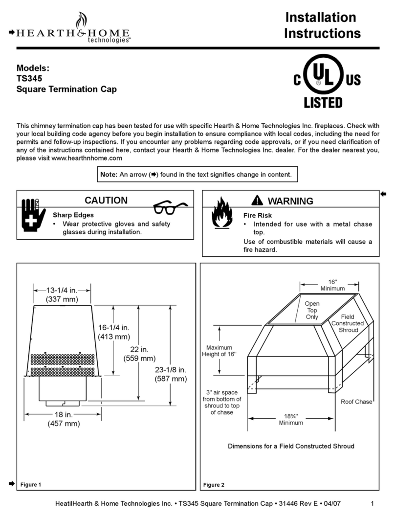
Hearth and Home Technologies Square Termination Cap TS345 User manual
Hearth and Home Technologies
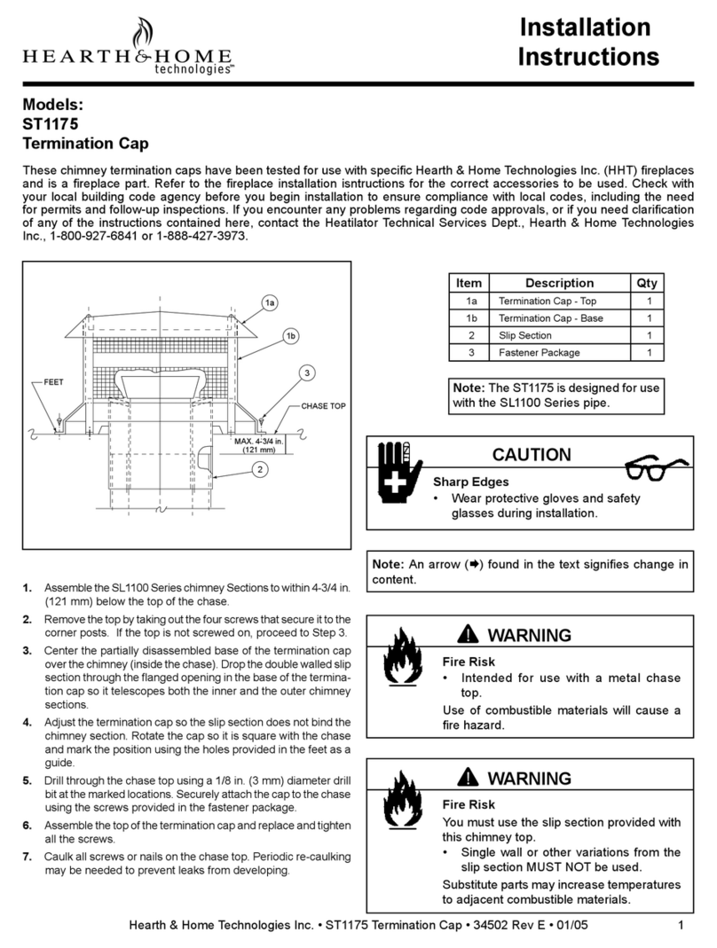
Hearth and Home Technologies Termination Cap ST1175 User manual

Hearth and Home Technologies
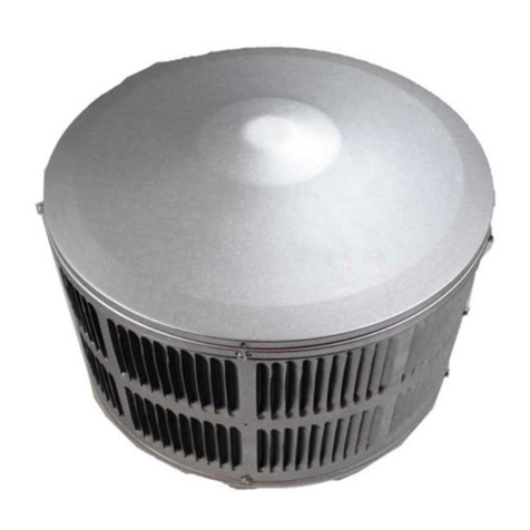
Hearth and Home Technologies Termination Cap ST375 User manual
Hearth and Home Technologies
Hearth and Home Technologies TR342 User manual
Popular Ventilation Hood manuals by other brands
Genfine
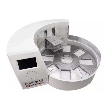
Genfine Purifier HT user manual
GE
GE JN327 Series Owner's manual and installation instructions

Electrolux
Electrolux IHL9028CN user manual

Ariafina
Ariafina MC Series Operation & installation manual
Fisher & Paykel
Fisher & Paykel HS60CIWX3 Installation instructions and user guide
Lamona
Lamona LAM2600 Installation & user's instructions
