Hearth Products Controls 19SS90HWI Installation instructions
1
828
Hearth Products Controls Co.
706 Congress Park Dr.
Dayton, OH 45459
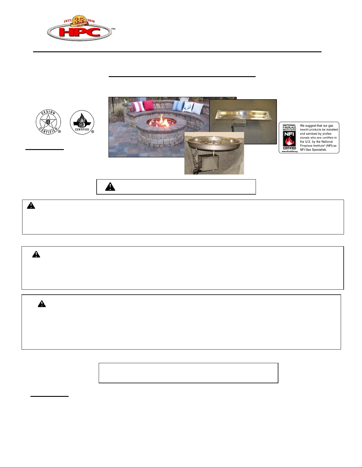
Remote Electronic HWI Fire Pit
Installation & Operation Instructions
(Exclusive Thermocouple / Hot Wire Ignition System)
Select Models Certified by
CSA International *
Meets: ANSI Z21.97-2010
ACR97-003 WARNING: FOR OUTDOOR USE ONLY
WARNING
•Improper installation, adjustment, alteration, service, or maintenance can cause injury or property
damage. Read the installation, operating, and maintenance instructions thoroughly before installing or
servicing this equipment.
WARNING
•Do not store or use gasoline or other flammable vapors and liquids in vicinity of this or any other
appliance.
•An LP-cylinder not connected for use shall not be stored in the vicinity of this or any other appliance.
DANGER
If you smell gas:
1) Shut off gas to appliance.
2) Extinguish any open flame.
3) If odor continues, keep away from appliance and immediately call gas supplier or fire
department.
INSTALLER: Leave this manual with the appliance.
CONSUMER: Retain this manual for future reference.
* Select Models CSA Certified: Bowl: 19SS90HWI, 25SS150HWI, 37SS300HWI-HC,
& 43SS400HWI-HC
Flat: 18FSS90HWI, 24FSS150HWI, 36FSS300HWI-HC,
& 42FSS400HWI-HC

2
2/22/2011 828
We require that our products be installed and serviced by professionals who are certified in t he U.S. by NFI
(National Fireplace Institute) or in Canada by WETT (Wood Energy Technical Training). Installer must follow
all instructions carefully to ensure proper performance and safety. Hearth Products Controls Company is not
responsible for your actions.
It is the responsibility of the installer to follow ALL LOCAL CODES concerning the installation and
operation of the fire pit. In the absence of local codes, please follow:
● Fixed piping system: The National Fuel Gas Code, ANSI Z223.1/NFPA 54 or International Fuel Gas
Code.
● Electrical ground: The National Electrical Code, ANSI/NFPA 70.
WARNING: REMOTE CONTROL USE: TO PREVENT ACCIDENTAL START UP
FROM UNWANTED RF SIGNALS, IT IS THE RESPONSIBILITY OF THE END USER
TO TURN OFF POWER TO ELECTRICAL OUTLET FOR THE REMOTE CONTROL
RECEIVER WHEN FIRE PIT IS NOT IN USE. THIS SHOULD BE DONE VIA WALL
SWITCH OR BREAKER.
IMPORTANT: Confirm your gas type matches the requirement for this fire pit- see label on fire pit
control box.
Gas Pressure: This should be checked prior to use:
● Natural Gas Fire Pit:
Supply Pressure: Minimum: 3.5” W.C.; Maximum: 7.0” W.C.
Outlet Pressure: 3.5” to 5.0” W.C.
Manifold Pressure: Nominal 3.5” W.C.
● LP Gas:
Supply Pressure: Minimum: 8.0” W.C.; Maximum: 15.0” W.C.
Outlet Pressure: 10.0” to 12.0” W.C.
INSTALLATION PREPARATION
Please carefully follow the steps below when: 1) Selecting the Location. 2) Construction of the Enclosure. 3)
Installation of the HWI Fire Pit.The steps listed as WARRANTY REQUIREMENT must be strictly followed to
qualify for product warranty. Warranty will be void if not followed.
SELECTING THE LOCATION
WARNING: HWI FIRE PITS ARE DESIGNED FOR OUTDOOR USE ONLY.
WARNING: FIRE PITS CREATE VERY HIGH TEMPERATURES- IT IS VERY IMPORTANT THAT
COMBUSTIBLES BE KEPT AT SAFE DISTANCES.
•Select a location where the fire pit can be attended during operation. Never leave an operating fire pit
unattended or by someone not familiar with its operation or emergency shut off locations.
Both children and adults should be alerted to the hazards of high surface temperatures and should stay away to
avoid burns and clothing ignition. Young children should be carefully supervised when they are in the area of fire
pit. Clothing or other flammable materials should not be placed on or near fire pit.
•WARRANTY REQUIREMENT: For installation of 110vac powered control systems, it is required to install a
wall switch or breaker for the fire pit electrical outlet away from the enclosure to prevent unwanted ignition of the
fire pit.
•WARRANTY REQUIREMENT: The fire pit location must accommodate a gas shut off outside of fire pit
enclosure. The gas line should be a minimum of 3/4” or larger based on fire pit size.
•To enjoy your fire pit, select a well drained location that allows for sufficient clearance from combustible
materials.
•Choose a location that allows easy access for installation and maintenance of the fire pit. Make sure that trees and
shrubbery are well clear around and above the fire pit.
•Pick a location that allows sufficient horizontal room to enjoy the fire pit while allowing a safe distance from the
heat and flame.
Combustibles must be located far enough away that there is no risk of ignition.
IMPORTANT: It is recommended that material such as granite, marble or other dense stone be kept away
from heat and especially flame due to risk of cracking. Manufacturer is not responsible for damage.

3
2/22/2011 828
Vents- 2 Total
HWI Fire Pit Clearances
Under Valve Box 6”
Sides Surrounding Fire Pit 48”
Overhead Clearance 120”
IMPORTANT: Overhead Clearance applies to tree limbs and branches only- DO NOT
install unit under overhang or ceiling.
CONSTRUCTION OF THE ENCLOSURE
WARNING:THERE MUST BE AN ELECTRICAL (WALL SWITCH OR BREAKER) AND GAS SHUTOFF ON THE
EXTERIOR OF THE FIRE PIT OR ON ADJACENT WALL TO ALLOW FOR EASY ACCESS FOR SHUTDOWN OR IN
THE CASE OF AN EMERGENCY.
WARNING: ALWAYS USE PROPER MATERIALS AND CONSTRUCTION FOR GAS SUPPLY, POWER, AND
ENCLOSURE.
•WARRANTY REQUIREMENT: The enclosure must be constructed on a stable surface. The weight of the fire
pit must be supported by the pan- not by the control box. Make sure that the fire pit is high enough that the control
valve box is above the grade to prevent water damage to the controls inside the box. NEVER install a HWI fire pit
below ground level. Drainage must be provided for the enclosure to prevent water accumulation leading to damage to
components in the valve box.
•WARRANTY REQUIREMENT: The enclosure must incorporate 1 vent on at least two sides at a minimum size
of 18 sq. inches each (Example: 3”x 6” or larger) to allow heat within the enclosure to escape. Failure to do so will
result in the fire pit automatically shutting down when
internal valve box temperature reaches 175º F. This could lead to heat damage to internal
components. Some enclosures may require more ventilation based on material, size, and
extended use. This vent may work as a drain as well when installed at bottom sidewall to prevent
water build up.
•WARRANTY REQUIREMENT: The interior void space of the enclosure surrounding the valve box cannot be
filled with any material (gravel, crushed rock, concrete, etc.)- It is a requirement to have a minimum of 6”under the
valve box for proper ventilation.
•Select materials that are non-combustible in both initial installations as well as over time.
•Make sure that the structure is level. We recommend the use of the installation collar (optional) that may be
mortared into the surround.
INSTALLATION OF THE HWI FIRE PIT ASSEMBLY
WARNING: INSTALLATION AND REPAIR SHOULD BE DONE BY A QUALIFIED SERVICE PERSON,
INSPECTED PRIOR TO USE AND AT LEAST ANNUALLY BY A QUALIFIED SERVICE PERSON.
WARNING: CONFIRM THIS APPLIANCE IS BUILT FOR GAS USED- NATURAL GAS OR LP. DO NOT USE
NATURAL GAS APPLIANCE WITH LP OR LP APPLIANCE WITH NATURAL GAS. REFER TO LABEL ON
THIS APPLIANCE.
WARNING: TO PREVENT DAMAGE, UNHOOK FIRE PIT FROM GAS SUPPLY FOR PRESSURE LEAK
TESTS GREATER THAN 1/2LBS PRESSURE (3.5K PA).
WARNING: GLASS MEDIA USAGE WITH LP GAS- WHEN USING APPROVED DECORATIVE
GLASS TO COVER BURNER APPLY ONLY ENOUGH TO HIDE BURNER. APPLYING OVER 1/2” MAY
CREATE BACK PRESSURE AND GAS LEAKAGE FROM AIR MIXER RESULTING IN LP POOLING
UNDER FIRE PIT. LAVA ROCK MAY BE APPLIED DEEPER DUE TO LARGER SIZE- LAVA ROCK
MAXIMUM DEPTH IS 3” ABOVE BURNER.
IMPORTANT: BURN TESTING- IT IS THE RESPONSIBILITY OF THE QUALIFIED INSTALLER TO
TEST FOR GAS LEAKS AT ALL CONNECTIONS.
ALSO WITH LP GAS THE UNIT MUST BE TESTED WITH MEDIA OVER BURNER FOR
CONFIRMATION OF NO BACK PRESSURE CREATING GAS TO LEAK OUT OF AIR MIXER VENTURI
HOLES. THIS MAY HAVE TO BE DONE PRIOR TO PLACING IN ENCLOSURE IF NO ACCESS DOOR.
●WARRANTY REQUIREMENT: The HWI fire pit should be supported by the pan when placed into enclosure.
The control box should not support weight of assembly.
•WARRANTY REQUIREMENT: The fire pit assembly should be recessed a minimum of 4” from the top of
the enclosure to protect flame from being blown out. Some areas may require
more- 8” is not uncommon.
•WARRANTY REQUIREMENT: All fire pits come with a 13” x 13” sheet of insulation between

4
2/22/2011 828
pan and valve box to protect internal components from heat damage. This may need to be
trimmed on smaller enclosures for proper fit. PLEASE USE THIS AT ALL TIMES.
•WARRANTY REQUIREMENT: Warranty is void if valve box is opened
•WARRANTY REQUIREMENT: When filling the pan with lava rock and/or decorative glass,
the instructions on Pg. 5 must be followed.
•The main gas should already be plumbed to the location of the fire pit area. The 24” flex line coming from the fire
pit should be connected to the main gas line. Tighten the flex line fittings to the gas supply stub and to the fire pit.
Avoid sharp bends with flex line to prevent whistling.
•Turn on main gas supply and check all fittings in and around fire pit for leaks using a leak reactant, leak detector
or soapy water. If leaks are found, shut off gas supply repair leaks and retest.
•The 3’ power cord can be either tied into the main power supply for use with wall switch or plugged into remote
receiver to use remotely. POWER MUST BE TURNED OFF TO ELECTRICAL OUTLET WHEN NOT IN
USE.
IMPORTANT: Please apply the Start Up and Shutdown decal next to control switch in an obvious position.
HWI FIRE PIT OPERATION
WARRANTY REQUIREMENT: WHEN NOT IN USE, THE FIRE PIT MUST BE COVERED AT ALL TIMES TO
PREVENT DAMAGE TO ELECTRONIC COMPONENTS.
WARNING: BEFORE USE, BE SURE TO TEST ALL GAS CONNECTIONS FOR LEAKS. DO NOT USE FIRE PIT IF
THERE IS ANY EVIDENCE OF LEAKING GAS. IF LEAKING GAS IS SUSPECTED, TURN OFF THE MAIN GAS
SUPPLY AND REPAIR IMMEDIATELY.
WARNING: DO NOT USE FIRE PIT IF ANY PART HAS BEEN SUBMERGED UNDER WATER. IMMEDIATELY
CALL A QUALIFIED SERVICE TECHNICIAN TO INSPECT THE FIRE PIT AND TO REPLACE ANY PART OF THE
CONTROL SYSTEM AND GAS CONTROL WHICH HAS BEEN UNDER WATER.
WARNING: WHEN FIRE PIT IS NOT IN OPERATION, POWER TO ELECTRIC OUTLET MUST BE TURNED
OFF VIA WALL SWITCH OR BREAKER.
WARNING: NEVER USE ANY MATERIAL THAT IS NON-POROUS AND HOLDS MOISTURE LIKE GRAVEL,
PEBBLES, RIVER ROCK, ETC. THIS MATERIAL, WHEN HEATED WILL CAUSE THE TRAPPED MOISTURE TO
BOIL, AND FRACTURE UNEXPECTEDLY. THIS MATERIAL IS NOT SUFFICIENTLY POROUS TO ALLOW HEATED
STEAM TO READILY ESCAPE WHICH CAN BREAK AND CAUSE PERSONAL INJURY OR DAMAGE.
WARNING: SOLID FUELS SHALL NOT BE BURNED IN FIRE PIT. LEAVES, STICKS, WOOD, PAPER,
CLOTHING, FOOD MATERIAL, SHOULD ALWAYS BE KEPT AWAY FROM THE FIREPIT. MAKE SURE THAT
THERE IS NO VEGETATION OR OTHER OBJECTS OVER THE TOP OR SIDES OF THE FIRE PIT THAT COULD
INTERFERE WITH SAFE & PROPER OPERATION.
WARNING: IF LAVA ROCK IS WET, ALLOW FIRE PIT TO BURN FOR 45 MINUTES PRIOR TO COMING 15 FEET
WITHIN FIRE PIT.
Fire Pit Start Up:
Initial Start-up: Several “on/off” cycles may be necessary to purge air in gas lines after system installation. Fire pit will
lockout after 15 attempts to light pilot: Please power OFF then ON to restart.
Sequence of Operation:
1. The hot wire igniter will be powered (glow red) for 5 seconds before pilot valve opens.
2. The hot wire igniter will only be powered the initial 15 seconds of the 60 second pilot cycle. This sequence will
repeat up to 15 times (~15 minutes) before going into lockout. To reset, turn “OFF” power then back “ON” again.
3. Pilot flame will ignite and warm thermocouple- it may take 30 seconds at times for thermocouple to get hot. If
thermocouple is not hot in 60 seconds, system will shutdown then go back to Step 1.
4. Once thermocouple is hot, main valve will open allowing main burner to ignite.
5. If pilot flame is blown out at anytime, system will shutdown, then automatically restart (Step 1).
NOTE: IF POWER TO FIRE PIT IS TURNED “OFF” THEN IMMEDIATELY TURNED BACK “ON” WHILE
MAIN BURNER IS “ON”, THE SYSTEM WILL GO INTO LOCKOUT MODE IF THERMOCOUPLE DOES
NOT COOL PRIOR TO 30 SECONDS AS A SAFETY FEATURE.
TO RESET, TURN “OFF” POWER THEN BACK “ON” AGAIN.
FIRE PIT START UP
1. STOP! Read the safety information on “What to Do If Smell Gas” (Pg. 1).
2. Confirm there is no debris in fire pit (as mentioned in warnings) including water.
3. Turn “ON” electrical power and gas to fire pit.
4. Using wall switch or remote, turn “ON” fire pit- this may take several cycles to
purge any air.
5. To reset after lockout, power unit down, wait 5 minutes, then restart.
6. Once fire pit has ignited, DO NOT leave unattended.

5
2/22/2011 828
OVERHEATING: The fire pit will automatically close gas valve if temperature exceeds 175º F inside valve box to prevent
component damage. When unit cools below 175º F, the unit will automatically restart. To correct overheating, ensure
enclosure has adequate ventilation- see “Construction of Enclosure”.
FIRE PIT SHUTDOWN
1. Turn “OFF” fire pit using remote control or wall switch.
IMPORTANT: REMOTE CONTROL USE: YOU MUST ALSO TURN OFF POWER TO
ELECTRICAL OUTLET OR GAS TO FIRE PIT TO PREVENT ACCIDENTAL START.
2. Once fire pit is cooled, use appropriate cover to protect fire pit.
Fire Pit Maintenance:
WARNING: ANY GUARD OR PROTECTIVE DEVICE REMOVED FOR SERVICING MUST BE REPLACED PRIOR
TO OPERATING THE FIRE PIT.
WARNING: INSTALLATION AND REPAIR SHOULD BE DONE BY A QUALIFIED SERVICE PERSON. IT SHOULD
BE INSPECTED PRIOR TO USE AND AT LEAST ANNUALLY BY A QUALILIFIED SERVICE PERSON.
1) Keep fire pit covered at all times when not in use.
2) Keep any debris out of fire pit- clean as needed.
3) Ring Cleaning:(1 x YR) If flames exhibit any abnormal shapes or behavior, or if burner fails to ignite properly, then the burner
holes may require cleaning. The appliance can be cleaned by carefully removing the logs and media to allow access to burner. Use a
brush to carefully remove dust, spider webs, and loose particles from base, logs, and fire ring itself. If evidence of damage, fire ring
must be replaced with fire ring specified by manufacturer.
4) Thermocouple Cleaning of Soot: (1 x 6 mos.) Remove lava rock & glass around pilot, then the blow out box lid. Clean
thermocouple of any soot using soft brush. Be careful not to damage hot wire element. Place lava rock or glass back as explained
below.
5) Visually inspect the pilot- The pilot flame should cover 3/8” to 1/2” of the thermocouple as shown below. Cleaning of orifice
may be required by removing pilot hood (CCW) and removing orifice as shown below.
Pilot Hood- turn CCW. Orifice
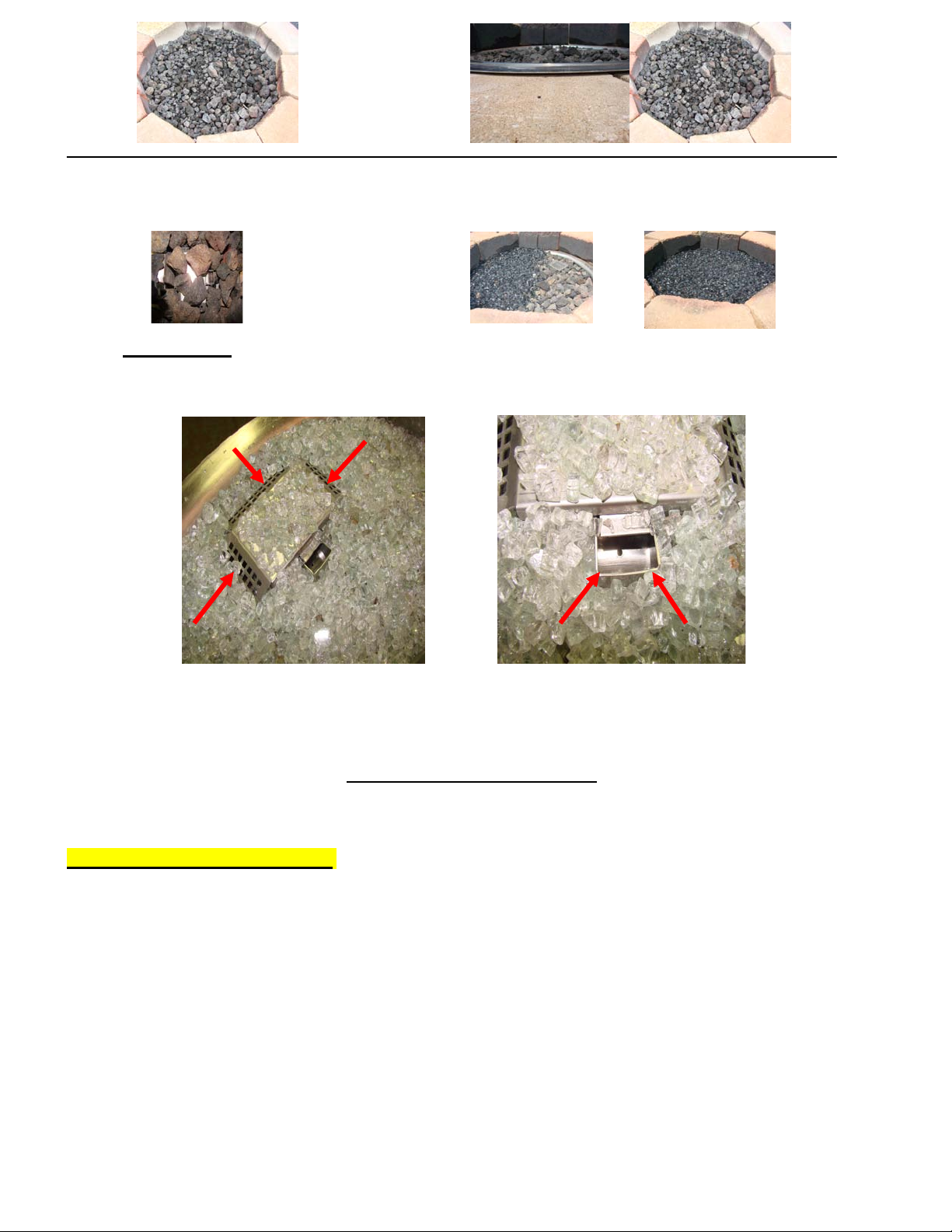
Lava Rock & Glass Application
Please follow the instructions below to add the finishing touch to your fire pit. Remember the
deeper your lava rock or glass the more risk of reducing if not smothering the flame. Particular
attention needs to be on the pilot assembly area- if blowout box vents are covered, this will cause the pit
to shutdown due to smothering pilot flame.
IMPORTANT: SEE BOXED WARNINGS ON PAGE 3 REGARDING LP & GLASS USAGE.
Lava Rock Only Application Decorative Glass Application
1) Install your fire pit per instructions. 1) Install your fire pit per instructions.
2) Apply lava rock ONLY deep enough to 2) Add base layer of lava rock as filler and hide fire
ring and pan- less than 2” to enhance flame. Height should be slightly above ring.
above fire ring. use smaller pieces rock supplied on top of ring.
6
2/22/2011 828
3) BLOWOUT BOX: Do not cover vents 3) Apply top coat of glass to lava rock,
with lava rock- leave open. Do not again just deep enough to hide lava rock
allow any rock to block flame opening. and pan.
Blowout Box: Do not cover blowout box vents or opening with lava rock or glass- this must
remain open. This will cause the pilot flame to suffocate and turn off pit.
DO NOT COVER VENTS! DO NOT COVER PILOT OPENING!
HWI Fire Pit Trouble Shooting
Below are some potential causes and countermeasures to the symptoms indicated in bold. Please
contact your retailer or certified technician for service & repair.
WARRANTY REQUIREMENT: Warranty is void if valve box is opened.
Hot Wire Will Not Glow
1. No power to unit. Confirm breaker, wall switch, and remote are on (120Vac)
2. Hi Limit Temp. Switch Tripping This will occur after fire pit has burned for awhile- see proper venting in
“Construction of Enclosure” (Pg. 3)
3. Hot wire element damaged Change hot wire element.
4. Damaged wires. Inspect wires to hot wire- confirm insulation is in good condition and
connections are tight.
No Pilot Flame (Hot Wire Glows)
1. Air in gas line. If new install, may take several attempts to purge air
2. Debris in gas line. Confirm gas line is clear (insulation, dirt, plastic etc..)
3. Gas Pressure Improper Confirm proper gas pressure found (Pg. 2)
4. Pilot Orifice Dirty Remove pilot head and clean orifice (Pg. 5)

7
2/22/2011 828
No Main Burner (Pilot Lights)
1. Gas Pressure Improper Confirm proper gas pressure found (Pg. 3)
2. Small Pilot Flame Remove pilot head and clean orifice.
Should be 3/8” flame on thermocouple (Pg. 5)
3. Dirty Thermocouple Clean using soft brush (Pg. 5)
4. Fire Ring Obstructed Confirm no debris or water in ring (Always cover fire pit!)
Main Burner Turning Off/On Frequently
1. Small Pilot Flame Remove pilot head and clean orifice (Pg. 4)
Should be 3/8” flame on thermocouple (Pg. 4)
2. Too much Media This will suffocate flame
over blow out box. See Pg. 5 for application of Lava Rock or Glass
3. Gas Pressure Improper Gas pressure too low (Pg. 3)
4. Thermocouple Defective Change Thermocouple.
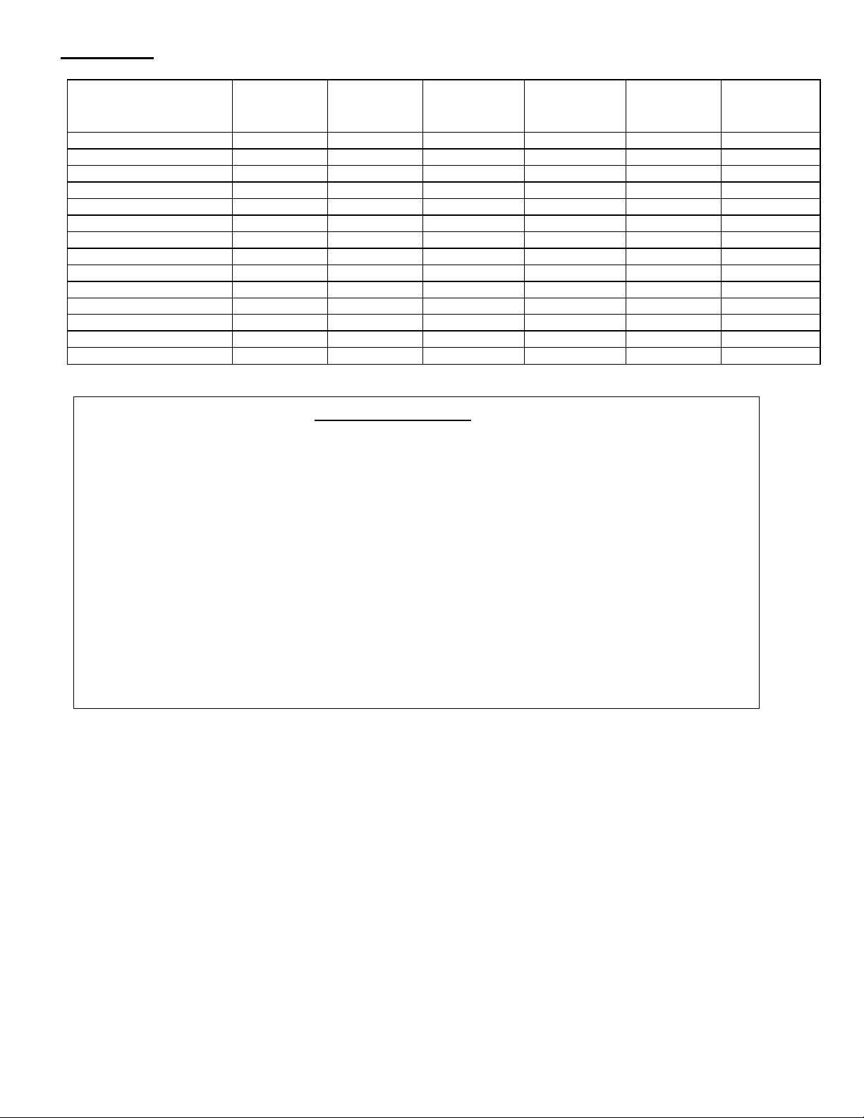
Replacement Parts
Please see list below for replacement parts as needed. Please contact your known dealer for these parts-
if unsure please contact HPC and we will be happy to help you.
Bowl Style Pan:
Component / Model # 19SS90HWI 25SS150HWI
31SS300HWI
37SS300HWI-
HC 43SS300HWI-HC
Fire Ring FRS-12 FRS-18 FRS-24 FRS-30HC FRS-36HC
Pan 570-19 570-25 570-31 570-37HC 570-43HC
Thermocouple 311-T/C 311-T/C 311-T/C 311-T/C 311-T/C
Igniter 913-HWI 913-HWI 913-HWI 913-HWI 913-HWI
Pilot Gas Line 654 654 654 654 654
Blow Out Box 598HWI 598HWI 598HWI 598HWI 598HWI
Flex Line SSC-HC24 SSC-HC24 SSC-HHC24 SSC-HHC24 SSC-HHC24
Insulation FPI-13SQ FPI-13SQ FPI-13SQ FPI-13SQ FPI-13SQ
Nat. Gas Orifice 677SS-90 677SS-150 677SS-300 677SS-300HC
LP Air Mixer
FPSLPK-90
FPSLPK-150
FPSLPK-300
FPSLPK-300HC
FPSLPK-400HC
Remote Control 578-C 578-C 578-C 578-C 578-C
Lava Rock 657 657 657 657 657
Control Box MVK HW90-X MVK HW150-X MVK HW300-X MVK HW300-X MVK HW300-X
Vinyl Cover FPC-45 FPC-45 FPC-53 FPC-53 FPC-53
Flat Style Pan:
Component / Model # 18FSS90HWI 24FSS150HWI
30FSS300HWI
36FSS300HWI-
HC
42FSS300HWI-
HC
Fire Ring FRS-12 FRS-18 FRS-24 FRS-30HC FRS-36HC
Pan 571-18 571-24 571-30 571-36HC 571-42HC
Thermocouple
311-T/C
311-T/C
311-T/C
311-T/C
311-T/C
Igniter 913-HWI 913-HWI 913-HWI 913-HWI 913-HWI
Pilot Gas Line 654 654 654 654 654
Blow Out Box 598HWI 598HWI 598HWI 598HWI 598HWI
Flex Line SSC-HC24 SSC-HC24 SSC-HHC24 SSC-HHC24 SSC-HHC24
Insulation FPI-13SQ FPI-13SQ FPI-13SQ FPI-13SQ FPI-13SQ
Nat. Gas Orifice 677SS-90 677SS-150 677SS-300 677SS-300HC
LP Air Mixer FPSLPK-90 FPSLPK-150 FPSLPK-300 FPSLPK-300HC FPSLPK-400HC
Remote Control 578-C 578-C 578-C 578-C 578-C
Lava Rock 657 657 657 657 657
Control Box MVK HW90-X MVK HW150-X MVK HW300-X MVK HW300-X MVK HW300-X
Vinyl Cover FPC-45 FPC-45 FPC-53 FPC-53 FPC-53
8
2/22/2011 828
Tough Style:
Component / Model #
24SS50HWI-
TRGH
36SS75HWI-
TRGH
48SS100HWI-
TRGH
60SS125HWI-
TRGH
72SS150HWI-
TRGH
96SS200HWI-
TRGH
Fire Ring TBSS-24 TBSS-36 TBSS-48 TBSS-60 TBSS-72 TBSS-96
Pan LFPSS-24 LFPSS-36 LFPSS-48 LFPSS-60 LFPSS-72 LFPSS-96
Thermocouple 311-T/C 311-T/C 311-T/C 311-T/C 311-T/C 311-T/C
Igniter 913-HWI 913-HWI 913-HWI 913-HWI 913-HWI 913-HWI
Pilot Gas Line 654 654 654 654 654 654
Blow Out Box 598HWI 598HWI 598HWI 598HWI 598HWI 598HWI
Flex Line SSC-HC24 SSC-HC24 SSC-HHC24 SSC-HHC24 SSC-HHC24 SSC-HHHC24
Insulation FPI-13SQ FPI-13SQ FPI-13SQ FPI-13SQ FPI-13SQ FPI-13SQ
Nat. Gas Orifice
677SS-50
677SS-75
677SS-100
677SS-125
677SS-150
677SS-200
LP Air Mixer FPSLPK-50 FPSLPK-75 FPSLPK-100 FPSLPK-125 FPSLPK-150 FPSLPK-200
Remote Control 578-C 578-C 578-C 578-C 578-C 578-C
Lava Rock 657 657 657 657 657 657
Control Box MVK HW50-X MVK HW75-X MVK HW100-X MVK HW125-X MVK HW150-X MVK HW200-X
Cover TPHC-24 TPHC-36 TPHC-48 TPHC-60 TPHC-36 x 2ea. TPHC-48 x 2ea.
Limited Warranty
Hearth Products Controls Company (HPC) warranties HWI fire pits against
manufacturing defects that prevent safe and correct function as follows:
●Electronics, Gas Valve, & Pilot Assembly: Commercial-6mos; Residential- 1 yr.
●Stainless Steel Pan, Fire Ring, & Valve Box: Commercial-1yr.; Residential 3yrs.
This commences from the date of original sale / shipment from HPC FOB Dayton, Ohio.
This warranty is for parts and in-house (HPC) labor. The defective product must be
sent back to HPC with a Return Merchandise Authorization (RMA) issued by HPC for
that specific product and any other additional information for the nature of the defect
or warranty claim.
The warranty does not cover items that have been damaged by overheating,
modification, abuse, or improper storage. Also any labor involving installation or
maintenance with the unit is not covered.
This warranty excludes claims for consequential, indirect-collateral expenses
arising from product defects or warranty recovery.
This manual suits for next models
7
Table of contents
Other Hearth Products Controls Outdoor Fireplace manuals


