Heartland Appliances Legacy 3530 Operating instructions

1050 Fountain St. N., Cambridge, Ontario, Canada N3H 4R7
ATTENTION INSTALLER:
Leave this manual with appliance
Bus. (519) 650-5775 or Fax (519) 650-3773
Toll Free Phone 1-800-361-1517
Toll Free Fax 1-800-327-5609
#3937 032205 © 2005HEARTLANDAPPLIANCESINC.
Note:Please readthese instructionsthoroughly beforeattempting toinstall thisunit. Failure
to follow installation instructions will result in costly service calls.
This appliance can only be installed in the state of Massachusetts by a Massachusetts
licensed plumber or gasfitter.
Save these instructions for future use
Model 3530-3630
Model 3535-3635
NOTE: Clock must
be set or your
oven will not
function!
Thesesymbolsonthenameplatemeantheproducthasbeendesign
certified by C.S.A International Laboratories
C
CERTIFIED
®
US
Installation and Operation Guide
30” and 36” Gas/Electric Professional Style
Cook Stove

WARNING
nAll ranges can tip
nInjury to persons could
result
nInstall anti tip devices
packed with range
nSee installation instructions
Models 3530-3630
Models 3535-3635
Installation and Operation Guide

Gas Top/Electric Convection
Self Clean Models 3530/3535 & 3630/3635
CONSUMER WARRANTY
ENTIRE PRODUCT – LIMITED ONE YEAR WARRANTY
HEARTLANDwarrantsthe replacement orrepairof all parts,includinggas componentsofthis Cookstove which
provetobedefectiveinmaterialorworkmanship,withtheexceptionofthepaintedorporcelainenamelfinishand
plated or stainless steel surfaces, for one year from the date of original purchase. Such parts will be repaired or
replaced at the option of Heartland without charge, subject to the terms and conditions set out below.
Thewarrantyperiodagainstdefectsinthepaintedorporcelainenamelfinishandplatedorstainlesssteelsurfaces,
is90daysfromdateoforiginalpurchase.Thewarrantydoesnotincludereplacementofovenlampsorfilters.
OVEN ELEMENTS - LIMITED SECOND THROUGH THIRD YEAR WARRANTY
HEARTLAND warrants the oven heating elements against defects in material or workmanship for an additional
twoyears.ThesepartswillberepairedorreplacedattheoptionofHeartlandwithoutcharge,butyoupayforlabour
and transportation subject to the terms and conditions set out below.
TERMS AND CONDITIONS
1. This warranty applies only for single family domestic use when the Cookstove has been properly installed
accordingtotheinstructionssuppliedbyHeartlandandisconnectedtoanadequateandproperutilityservice.
Damage due to faulty installation, improper usage and care, abuse, accident, fire, flood, acts of God,
commercial, business or rental use, and alteration, or the removal or defacing of the serial plate, cancels all
obligationsof thiswarranty. Serviceduringthiswarrantymustbeperformedby afactory AuthorizedService
Person.
2. Warranty applies to product only in the country in which it was purchased.
3. Heartland is not liable for any claims or damages resulting from any failure of the Cookstove or from service
delays beyond their reasonable control.
4. To obtain warranty service, the original purchaser must present the original Bill of Sale, Model and Serial
number. Components repaired or replaced are warranted through the remainder of the original warranty
period only.
5. The warranty does not cover expense involved in making this appliance readily accessible for servicing,
replacement of house fuses or fuse boxes, or resetting of circuit breakers.
6. Thiswarrantygivesyouspecificlegalrights. Additionalwarrantyrightsmaybeprovidedbylawinsomeareas.
7. Adjustments such as education of customer in proper use and care of product calibrations, air shutter
adjustments, levelling, tightening of fasteners, or utility connections normally associated with original
installation are the responsibility of the dealer or installer and not that of the Company.
8. Breakage,discolorationordamagetoglass,metalsurfaces,plasticcomponents,trim,paint,porcelainor other
cosmetic finish, caused by improper usage or care, abuse, or neglect is not covered under this warranty.
PLACEOFPURCHASE______________________________
DATEOFPURCHASE_______________________________
SERIALNUMBER__________________________________
MODELNUMBER__________________________________
Customer Service
Heartland Appliances Inc.
1050 Fountain St. N., Cambridge,
Ontario, Canada N3H 4R7
Bus.(519)650-5775orFax(519)650-3773
Toll Free Phone 1-800-361-1517
Toll Free Fax 1-800-327-5609
Fill in the spaces below for future reference, should service be required. Iffurtherhelpis needed concerningthis
warranty, contact:

Metro / Legacy Series
Section 1: Set Up & Assembly ....................2
Safety Instructions .......................................... 2
Preparing the Installation Site......................... 2
Installation Clearances.................................... 2
Exhaust Hood.................................................. 3
Electrical Installation ...................................... 3
Gas Line Installation....................................... 3
Clearance Diagrams........................................ 4
Preparing the Range for Installation ............... 8
Positioning the Range ..................................... 9
Section 2: Safety Guidelines......................10
Important Safety Instructions ....................... 10
Oven Safety................................................... 10
Self Clean Safety Instructions ...................... 11
Exhaust Hood Safety .................................... 11
Selecting the Proper Cookware .................... 12
Section 3: Cooking Controls .....................13
Cooktop Features .......................................... 13
Oven Features ............................................... 13
Cooking Controls Diagrams ......................... 14
Control Panel Lay Graphic ........................... 15
Electronic Oven Control Features ................ 16
Section 4: Oven & Clock Operation ........17
1. General Information.................................. 17
2. Safety Features.......................................... 18
3. Oven Light ................................................ 18
4. Clock Operation ........................................ 18
5. Minute Minder .......................................... 20
6. Bake .......................................................... 21
7. True Convection ....................................... 24
8. Convection Bake....................................... 37
9. Broil .......................................................... 30
10.Convection Broil...................................... 30
11.Sabbath Mode .......................................... 32
12. Self Clean................................................ 34
Section 5: Top Burner & Grill Operation36
Lighting the Top Burners and Grill .............. 36
Small Pot Ring / Trivet ................................. 36
Section 6: Baking, Broiling & Roasting...37
Standard Baking............................................ 37
Standard Broiling.......................................... 37
True Convection ........................................... 38
Convection Bake........................................... 38
Convection Roasting..................................... 38
Convection Broil........................................... 38
Sabbath Mode ............................................... 38
Broiling Tips ................................................. 39
Section 7: Care & Cleaning ......................40
Porcelain – Legacy Series............................. 40
Stainless Steel – Metro Series ...................... 40
Oven Cleaning - Self Clean .......................... 41
Surface Burners............................................. 42
Nickel Plated Parts........................................ 42
Oven Light Replacement .............................. 42
Grill ............................................................... 43
Interior Oven Rack........................................ 44
Rack Supports ............................................... 44
Oven Door Removal ..................................... 45
Section8:TroubleShooting .......................46
Burner Set Up and Adjustment ..................... 46
Problem Solver - Range Oven ...................... 47
Power Failure Operation ............................... 48
GasTroubleShooting .................................... 48
Gas Trouble Shooting Chart .......................... 49
Section 9: Reference ..................................50
Accessories ................................................... 50
Conversion Kits and Information ................. 50
Parts Drawing ............................................... 51
Parts Description........................................... 52
Heartland Kitchens ....................................... 53
AppendixA:CookingGuides...................56
Meat Roasting Guide .................................. iii
Poultry Roasting Guide ............................... iv
Broiling Guide ............................................ v
Baking Guide ............................................. vi
Grilling Guide ............................................. vii
Table of Contents

2
Metro / Legacy Series
Set Up and Assembly
Safety Instructions
Pleasecheckfor anydamagethatmay have
occurredduringshipping. Intheunlikelyevent
thatyoufindanyshippingdamage,informyour
dealerimmediately!
LegacyandMetro rangesconsistofthe range
bodyandthesplashback. The splashback is
fastenedtothe backofthestove forshipping
purposes.
Toolsrequiredforassembly:
• Screwdriver
• Utilityknife
• Level
• Metalshears
• Hammer
Youmusthaveaqualifiedelectriciancon-
nect the new range to be sure all electrical
codes and regulations are observed except
whenrangeisequipped withacordand
plug. Aqualifiedgastechnicianmustinstall
thisappliancetoensurelocalinstallation
codesandregulations are observed.
Preparing the Installation Site
Findtheappropriateclearance/installation
diagramfor yourrange onthe followingpages.
(seefig 1& 2) Diagramsincludeinstallations
withanexhausthood.
Thesediagramswilloutlinetherequiredopening
foryourrangeand clearances tocupboards,
electricaloutlets,and gas outlet. Siteprepara-
tioncanbe madetohave theseutilitiesready
priortoreceiptof the rangeandsplashback.
Alsorequired beforeinstallation ofyourrange,
istheplacing oftheAnti -tipbracket.
Followthisproceduretoinstall the antitip
bracket.
1)theanti tip bracketpackage(complete with
screws)isfound intheaccessory boxinsidethe
oven.
2)onthe wall measureupfrom thefloor55/8”
andmarkthatpositionwith apencil,thisisthe
correctheightofthe tab on thebracket.
3)atthe5 5/8”height locateawall stud along
thathorizontalplane.
4)fastenthebrackettothewallstud at the 5 5/8
heightwiththe2screwssupplied.
5)usethe twoholesimmediately abovethetab
intheleftside of thebracket,ifthere is ablock-
agepreventingthe useofthese holes,usethe
alternateholesin rightsideof the bracket.
use these holes to mount
bracket
this tab fits over the bottom panel of
the appliance, when the appliance is
slid into place.
alternate mounting holes
Anti - tip bracket diagram
Installation Clearances
Shouldtherange beinstalledadjacent toarefrig-
erator,itisimportantthattherebeaminimumof5”
(30cm)ofspacebetween the twoappliancesfor
properair circulation.
Installationofcabinetstoragespaceabovethesur-
faceburnersshouldbeavoidedatallcoststoelimi-
natetheriskof burns orfirebyreaching over the
surface burners. If combustible materials are
presentabovethecookingsurfacetheyshouldbe
ataminimumdistanceof36”fromthesurfaceburn-
ers.

Section 1: Set Up and Assembly
3
Yourrangeshouldbelevelforbestcookingresults.
To verify, place a carpenter’s level on top of the
cookingsurfaceandacrosstheovenrack. Ifleveling
isrequired,adjustthelevelingscrewsunderoneor
moreofthelegsaccordingly.(see“Positioningthe
Range”stepinthissection)
Tofacilitatetheinstallationofyourrange,allfourlegs
areequippedwithTeflongliders. Topreventscratches
ensure that the gliders and kitchen floor are
freeofanydebris.
Exhaust Hood
Anexhausthood mustbeinstalled overyournew
appliance.(seefig1) MatchingLegacyandMetro
exhausthoodsareavailablefromyourdealer. You
mayalsocallHeartlandAppliancesdirectlyforpricing
information. Our hoodsaredesignedandbuiltto
complementyourrange’svisualappealandperform
ance.
Shouldyouwishtoinstallanexhausthoodofyour
ownchoice,ensurethattheexhausthoodyoupurchase
isthecorrectsizeandcapacityfor yourHeartland
range. Pleasefollowtheexhausthoodmanufacturers
installationinstructions. Wheninstallinganaftermarket
exhaust hood over a Heartland appliance we
recommendthatyouusetheclearancesasshownin
theclearancediagramsforexhausthoodinstallations.
VentingSafetyGuidelines:
Installationmustbecompletedinaccordancewithall
localandnationalcodes. Useonlymaterialswhich
conformtolocalcodesineffect. Besurethepower
isdisconnectedbeforedoinganyelectricalwork. All
ductworkmustbemetal. Donotuse plasticduct.
The range hood should never be exhausted into a
wallcavityoranatticwhereanaccumulationofgrease
couldbecomeafirehazard. Whentheinstallationis
completed,turnonthefanandmakesurethatthere
arenoobstructionsintheline.
Electrical Installation
Electricalrequirements:standard24060Hz(4.5Kw
for 30” models and 5.6 Kw for 36” models) volt
receptacle,properlypolarized,onit’sownline.Ranges
areprovidedwithamouldedonplugcappowercord
rated120/240volts
Models 3520/3525 and 3620/3625 gas/electric
rangesmustbeelectricallygroundedincompliance
withlocalcodes. Intheabsenceoflocalcodes,the
installationmustconformwiththeNationalElectrical
Code.Disconnecttheelectricalsupplybeforeservicing
Gas Line Installation
Gas requirements: 30” and 36” models can be
operatedwitheithernaturalgasorliquidpropane(LP).
Therangesaresetfor eithernaturalgasORpropane
atthefactory. Aconversionkitmaybepurchasedat
alatertimeandinstalledonsiteshouldtheneedarise.
Theappliancerequiresa½” NPTconnector. Use
only approved pipe. Check that your range is
correctlyinstalledbyaqualifiedtechnicianorinstaller
for the type of gas used.Use minimum 5/8”
diameterflexibleline.
Therangemustbeinstalledincompliancewithlocal
codes. In the absence of local requirements, the
installationmustconformwiththeNationalGasCode.
Note: Appliances installed in the state of
Massachusetts:-Thisappliancecanonlybeinstalled
in the state of Massachusetts by a Massachusetts
licensedplumberorgasfitter-Thisappliancemustbe
installedwithathree(3)foot/36inchlongflexible
gasconnector.A“T”handletypemanualgasvalve
mustbeinstalledinthegassupplylinetothisappliance
Duringanypressuretestingofthegassupplypiping
system, at test pressures equal to or less than 2.5
KPS, the appliance must be isolated from the gas
supplypipingsystembyclosingitsindividualmanual
shutoffvalve.
The maximum propane/natural gas supply inlet
pressuremustnotexceed14”ofwatercolumn. The
minimumgassupplyinletshouldbeatleast6”ofwater
columnfornaturalgasoratleast11”ofwatercolumn
forLPgas.
theappliance.
4
Metro / Legacy Series
Dim 36" Metro
G25 1/2" (65cm)
H36" (92.5cm)
I12" (30.5cm)
J37" (94cm)
K5 5/8"(14.5cm)
L2" (5cm)
M18" (38cm)
N20" (51cm)
O6" (6cm) min left and right side
P13" (33cm)
QSPECIFYWIDTH OF HOOD
R24" (61 cm)
S30" (76cm) min - 36" (92 cm)
for standard and high back guard
S130" (76 cm) min -
33 1/2" (85cm) max.
for low profile back guard only
T18" (45cm)
Edges of
counter top
must be finished
G
H
I
JK
O
cupb
mus
26”
oard depth
t
not exceed
L
M
P
Q
R
S
S1
N
Gas Inlet
Anti-tip
bracket
T
Clearances
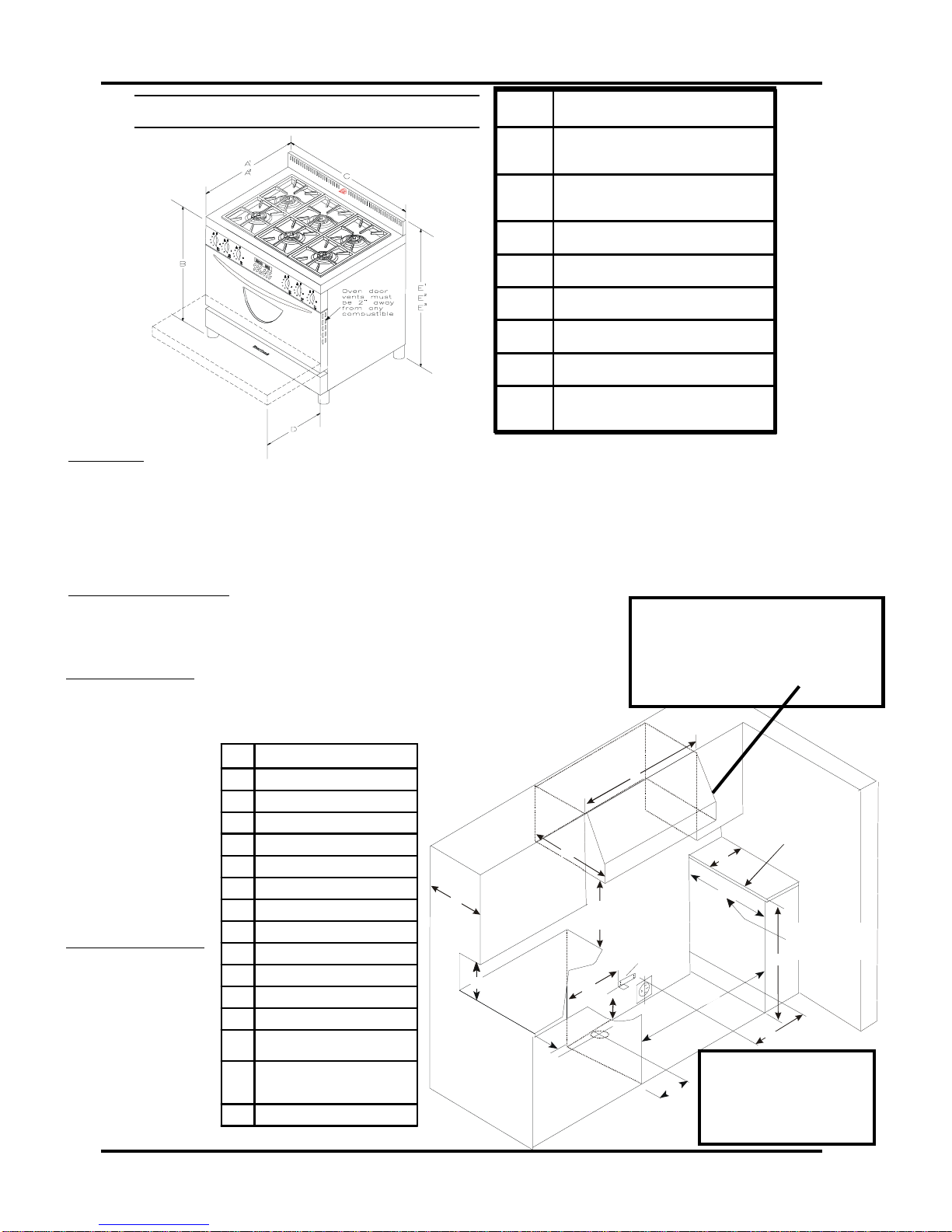
• Oven door vents must be 2" from any combustible. Door vents are required on Metro units to allow oven door ventilation.
• Minimum distance between the range and a side wall above the cooking top surface is 6” (see dim "O" in Table 2 below)
• 0” Clearance to the back of the stove may be obtained when installing the appliance against a non - combustible wall or
with the installation of our Splashback Kit. Responsibility for ensuring that the rear wall is non - combustible lies with the
owner or end user. (check local building codes) - if wall behind stove is deemed combustible and our splashback kit is not
installed, then the minimum spacing from the back of stove to nearest combustible wall is 6”
Electrical requirements:
• Electrical hookup must be done by a licenced electrician
• 240 Volts 60Hz 5.6 kW 3 prong plug for U.S. and 4 prong for Canadian installations.
(5 ft-1.5 m power cord included) New installations for the U.S. may require a four prong
plug, please confirm prior to ordering.
Figure 1 Table 1
For proper performance a 900 CFM vent
hood is required on all 36" Metro ranges
to ensure adequate and proper ventilation.
For superior ventilation we recommend
using a 42” hood, however a 36” hood is
adequate.
Note: If range must stand
beside a refrigerator, it is
important for proper air
circulation.There must be at
least 5” (125 mm) of space
between the two appliances.
Table 2 Figure 2
Dim 36" Metro
A128 3/4" (73cm)
to front of stove
A231 1/4" (79cm)
to ed
g
e of oven door handle
B36" 1/8 (92cm)
C36" (91cm)
D17 1/2" (79cm)
E1standard 40 5/8" (103cm)
E2low profile: 38" (97cm)
E3hi
g
h back , hi
g
h back w/shelf:
56 1/8" (143cm)
*
* U.S. models only: J=36 1/2”
Clearance Diagrams - 36” Metro
Gas Requirements:
• Gas hook-up must be done by a licensed gas fitter.
• Pressure requirements: Natural gas: 6” W.C. (min); LP
gas: 11” W.C. (min)
• Connection: 1/2”
NPT • 5/8” minimum
diameter flex line.
• An accessible
manual shut off valve
must be installed at
the appliance.
• Natural Gas/Pro-
pane Conversion kits
are available - must
be done by a licensed
gas fitter
Anti Tip Bracket:
bracket included with
every stove. When
properly installed, will
prevent stove from tip-
ping forward if down-
ward force is applied
to an open door.
Section 1: Set Up and Assembly
5
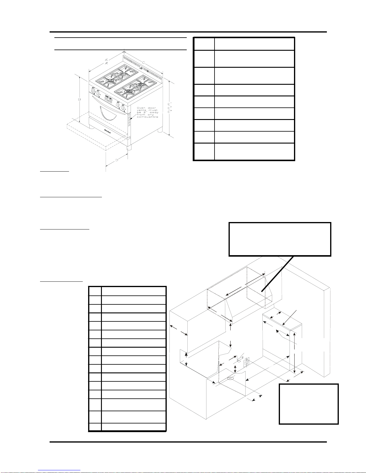
Dim 30" Metro
A128 3/4" (73cm)
to front of stove
A231 1/4" (79 cm)
to edge of oven door handle
B36 1/8" (92cm)
C29 3/4" (76cm)
D17 1/2" (45cm)
E1standard 40 5/8" (103cm)
E2low profile: 38" (97cm)
E3high back w/shelf:
56 1/8" (143cm)
Clearances
• Oven door vents must be 2" from any combustible. Door vents are required on Metro units to allow oven door ventilation.
• Minimum distance between the range and a side wall above the cooking top surface is 6” (see dim "O" in Table 2 below)
Electrical requirements:
• Electrical hookup must be done by a licenced electrician
• 240 Volts 60Hz 4.1 kW three prong plug for U.S. and four prong for Canadian installations. (5 ft-1.5 m power cord
included) New installations for the U.S. may require a four prong plug, please confirm prior to ordering.
Gas Requirements:
• Gas hook-up must be done by a licensed gas fitter.
• Pressure requirements: Natural gas: 6” W.C. (min); LP gas: 11” W.C. (min)
• Connection: 1/2” NPT • 5/8” minimum diameter flex line.
• An accessible manual shut off valve must be installed at the appliance.
• Natural Gas/Propane Conversion kits are available - must be done by a
licensed gas fitter
Anti Tip Bracket: bracket included with every stove.
When properly in-
stalled, will pre-
vent stove from
tipping forward if
downward force
is applied to an
open door.
Figure 1 Table 1
Table 2 Figure 2
Ed
g
es of
counter top
must be finished
G
H
I
JK
O
cupb
mus
26”
oard depth
t
not exceed
L
M
P
Q
R
S
S1
N
Gas Inlet
Anti-tip
bracket
T
Note: If range must stand
beside a refrigerator, it is
important for proper air
circulation.There must be
at least 5” (125 mm) of
space between the two
appliances.
Dim 30" Metro
GMaximum 26"" (66cm)
H36" (92.5cm)
I10" (25cm)
J30 3/4" (78cm)
K5 5/8"(14.5cm)
L2" (5cm)
M15" (38cm)
N10" (51cm)
O6" (15cm) min left and right side
P13" (33cm)
QSPECIFYWIDTH OF HOOD
R24" (61 cm)
S30" min to 36" max (76-92cm)
for standard and high back guard
S130" min to 33-1/2" max (76-85cm)
for low profile back guard only
T18" (45cm)
* U.S. models only: J=30 1/4”
*
Clearance Diagrams - 30” Metro
Forproper performancea 450CFM vent hood
is required on all 30" Legacy ranges to en-
sure adequate and proper ventilation. For su-
perior ventilation we recommend using a 36”
hood, how- ever a 30” hood is adequate.
6
Metro / Legacy Series
Edges of
counter top
must be finished
G
H
I
JK
O
cupb
mus
26”
oard depth
t
not exceed
L
M
P
Q
R
S
S
1
N
Gas Inlet
Anti-tip
bracket
T
Clearances
• Minimum distance between the range and a side wall above the cooking top surface is 6” (see dim "O" in Table 2 below)
• 0” Clearance to the back of the stove may be obtained when installing the appliance against a non - combustible wall or with the
installation of our Splashback Kit. Responsibility for ensuring that the rear wall is non - combustible lies with the owner or end
user. (check local building codes) - if wall behind stove is deemed combustible and our splashback kit is not installed, then the
minimum spacing from the back of stove to nearest combustible wall is 6”
Electrical requirements:
• Electrical hookup must be done by a licenced electrician
• 240 Volts 60Hz 5.6 kW 3 prong plug for U.S. and 4 prong for Canadian installations.
(5 ft-1.5 m power cord included) New installations for the U.S. may require a four prong
plug, please confirm prior to ordering.
Gas Requirements:
• Gas hook-up must be done by a licensed gas fitter.
• Pressure requirements: Natural gas: 6” W.C. (min); LP gas: 11” W.C. (min)
• Connection: 1/2” NPT • 5/8” minimum diameter flex line.
• An accessible
manual shut off
valve must be in-
stalled at the appli-
ance.
• Natural Gas/Pro-
pane Conversion
kits are available -
must be done by a
licensed gas fitter
Anti Tip Bracket: •
Bracket included
with every stove.
When properly in-
stalled, will prevent
stove from tipping
forward if down-
ward force is ap-
plied to an open
door.
Figure 1 Table 1
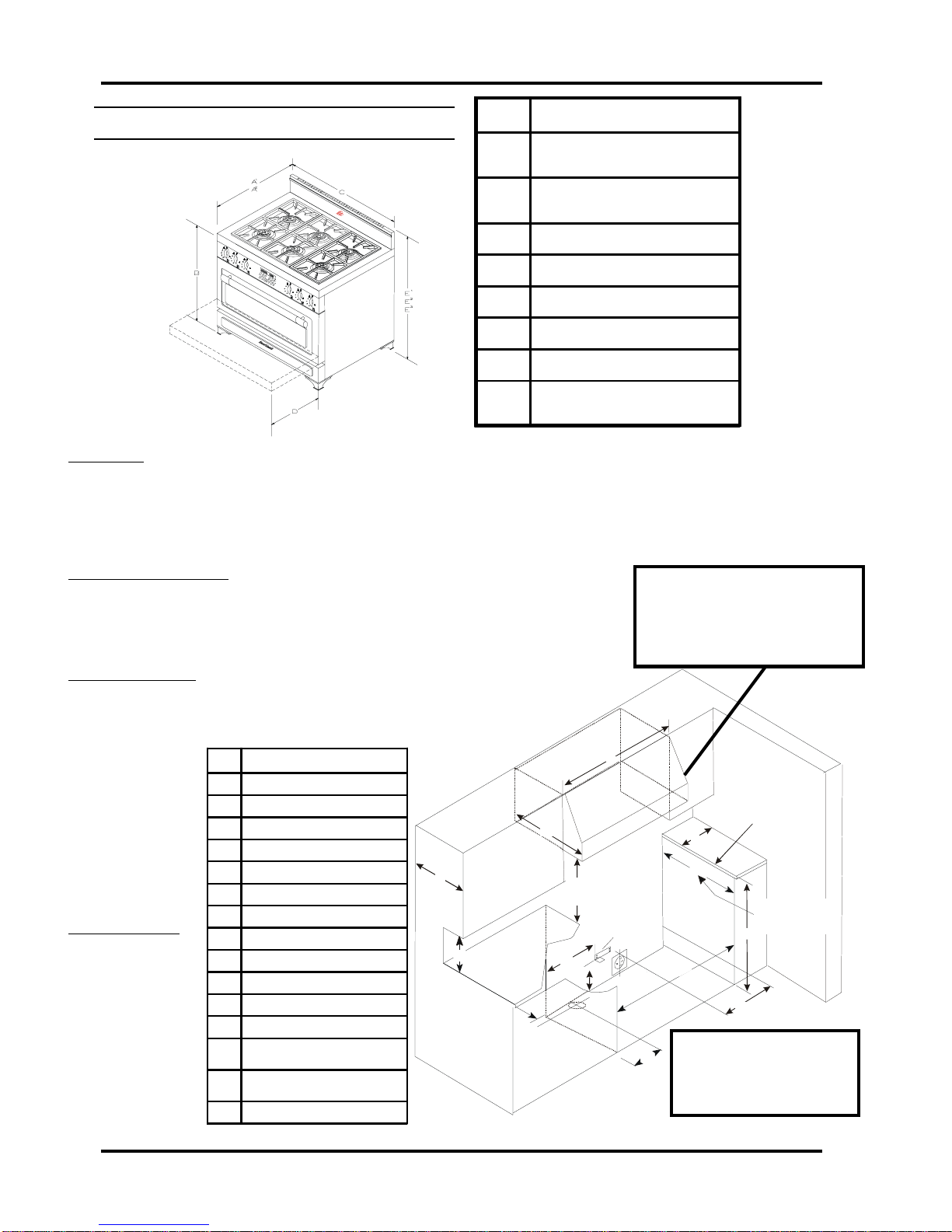
Dim 36" Legacy
A128 3/4" (73cm)
to front of stove
A231 1/2" (80 cm)
to edge of oven door handle
B36 1/8" (92cm)
C36" (91cm)
D17 1/2" (45cm)
E1standard 42 1/8 "(106cm)
E2low profile: 38" (97cm)
E3high back w/ shelf:
56 1/8" (143cm)
Clearance Diagrams - 36” Legacy
Dim 36" Legacy
GMaximum 26"" (66cm)
H36" (92.5cm)
I12" (30.5cm)
J37" (94cm)
K5 5/8"(14.5cm)
L2" (5cm)
M18" (46cm)
N16" (41cm)
O6" (15cm) min left and right side
P13" (33cm)
QSPECIFYWIDTH OF HOOD
R24" (61 cm)
S30" minto 36" max (76-92 cm)
for standard and high back guard
S130" minto 32" max (76-82 cm)
for low profile back guard only
T18" (45cm)
* U.S. models only: J=36 1/2”
*
For proper performance a 900 CFM vent
hood is required on all 36" Metro ranges
to ensure adequate and proper ventila-
tion. For superior ventilation we
recommend using a 42” hood, however
a 36” hood is adequate.
Note:Ifrangemuststandbeside
a refrigerator, it is important for
properaircirculation.Theremust
be at least 5” (125 mm) of space
between the two appliances.

Section 1: Set Up and Assembly
7
Clearances
• Minimum distance between the range and a side wall above the cooking top surface is 6” (see dim "O" in Table 2
below)
Electrical requirements:
• Electrical hookup must be done by a licenced electrician
• 240 Volts 60Hz 4.1 kW three prong plug for U.S. and four prong for Canadian installations. (5 ft-1.5 m power cord
included) New installations for the U.S. may require a four prong plug, please confirm prior to ordering.
Gas Requirements:
• Gas hook-up must be done by a licensed gas fitter.
• Pressure requirements: Natural gas: 6” W.C. (min); LP gas: 11” W.C. (min)
• Connection: 1/2” NPT • 5/8” minimum diameter flex line.
• An accessible manual shut off valve must be installed at the appliance.
• Natural Gas/Propane Conversion kits are available - must be done by a licensed gas
fitter
Anti Tip Bracket:
bracket included
with every stove.
When properly in-
stalled, will prevent
stove from tipping
forward if downward
force is applied to
an open door.
Figure 1 Table 1
Edges of
counter top
must be finished
G
H
I
JK
O
cupb
mus
26”
oard depth
t
not exceed
L
M
P
Q
R
S
S
1
N
Gas Inlet
Anti-tip
bracket
T
Note: If range must stand
beside a refrigerator, it is
important for proper air
circulation.There must be at
least 5” (125 mm) of space
between the two appliances.
Table 2
Figure 2
Dim 30" Legacy
A128 3/4" (73cm)
to front of stove
A231 1/2" (80cm)
to edge of oven door handle
B36 1/8" (92cm)
C29 3/4" (76cm)
D17 1/2" (45cm)
E1standard 42 1/8" (106cm)
E2low profile: 38" (97cm)
E3high back w/shelf:
56 1/8" (143cm)
Clearance Diagrams - 30” Legacy
Dim 30" Legacy
GMaximum 26" (66cm)
H36" (92.5cm)
I10" (25cm)
J30 3/4" (78cm)
K5 5/8"(14.5cm)
L2" (5cm)
M15" (38cm)
N10" (51cm)
O6" (15cm) min left and right side
P13" (33cm)
QSPECIFYWIDTH OF HOOD
R24" (61 cm)
S30" min to 36" max (76-92cm)
for standard and high back guard
S130" min to 32" max (76-82cm)
for low profile back guard only
T18" (45cm)
*
*U.S. models only: J=30 1/4”
Forproper performancea 450CFM vent hood
is required on all 30" Legacy ranges to en-
sure adequate and proper ventilation. For su-
perior ventilation we recommend using a 36”
hood, however a 30” hood is adequate.
8
Metro / Legacy Series
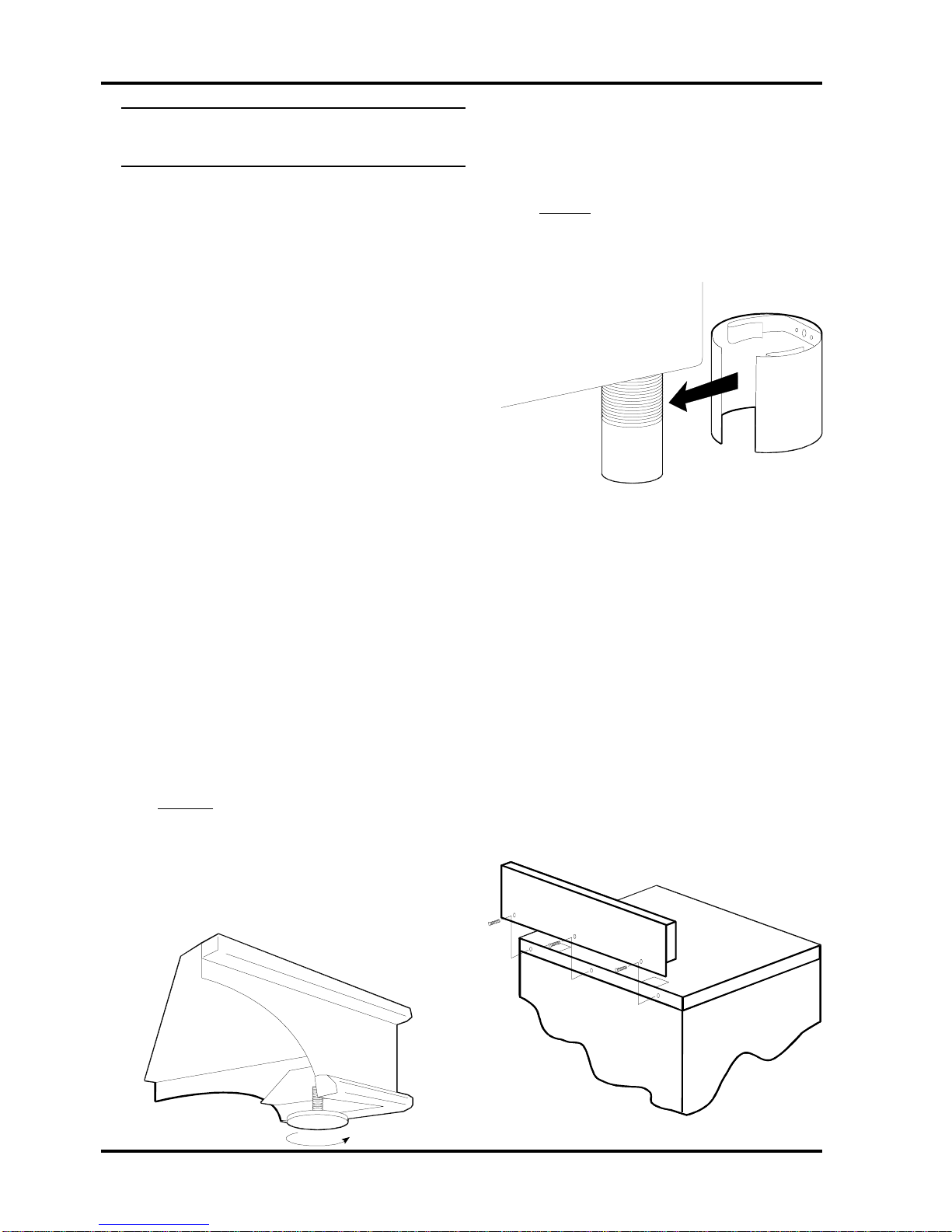
(fig6)
Preparing the Range for
Installation
1. Carefullyremovebandingwithmetal
shears. Caution:bandingmaybeunder
pressure,wearglovesto protect hands
fromaccidentalcuts.
2. Remove crating,cardboard,and plastic
packagingmaterial. Toavoiddamageto
thefinish oftherange,please usecaution.
3. Remove grates,ovenracks, bakingtrays,
andaccessorypackagefrom the oven.
Setthemaside. Ovenracksandgrates
shouldbewashed in warmsoapywater,
priortouse.
4. Removepackagingfrom top of burners.
Theburnersareshippedcompletely
assembledandarepre-adjusted for the
gassettingordered–natural gas or pro-
pane.
5. Carefullylifttherangeoffpalletandonto
thefloordirectlyinfront ofthegasand
electricalconnections. Twopeopleare
requiredtoliftthestove intoposition. In
ordernotto damagetherange,refrain
fromliftingbythetop. Onlylifttherange
aroundthebottomofthe oven body – one
persononeachside.
6. Legassembly.
i.Legacy.
Adjustbaselevelingbolts(withTeflon
gliderattached)so thattheyextend
beyondthebottomofthe leg by ap-
proximately1/8”–1/4”(0.3cm-0.6cm).
(fig 4)
(fig5)
Adjusting thelevellingboltsintoofar
willcausethe legtodrag onthefloor.
Thiscould potentiallycause damageto
flooring.(seefig4)
ii.Metro.
Legsarepre-adjusted for level. They
mayrequireonlyaslightadjustment.
Locatetheleg coversinsidethe oven.
Unwrapandsnap coversintoposition.
(fig5)
7. Assemblethesplashback. (fig6) Locate
thesplashbackatthebackof the stove.
Removescrewsandsplashback. Donot
throwthesescrewsaway– they are
requiredtoreinstall thesplashback. Posi-
tionsplashbackon range. Lineupholes in
thesplashbackwith the holesattheback
oftherange. Usingscrews and screw-
driverprovided,assemble thesplashback
totherange.

9
Section 2: Safety Guidelines
Positioning the Range
(fig7)
1. Whenthe rangeis fullyassembledandthe
gasline installed,insertthe240voltplug
intothereceptacle. Check that allnutsand
boltshavebeentightened.
2. EnsureTeflonglidersandflooringare
cleanandclear of alldirtanddebris. (as
describedin“PreparingtheInstallation
Site”)
8.Ifyouareinstallinga20”highprofile
backguard:
a.Unpackage.
b.Secure20”high profile backtothestove
topusing:
3-large metalwashers.
3-small metalwashers.
3-stainless steel screws.
c. Securebackpaneltothe 20” high
profilebackusing:
9-black sheet metal screws.(do not secure t
hethreebottom holes atthistime)
d. Secure brackets (#3266-3 pcs.)to the 20”
highprofilebackandstovetop,using6black
sheetmetalscrews.
(fig7)
Push here
8. Range isnowready forgasconnection by
aqualifiedtechnician/installer.
3. Caution. Onflooringwithveryrough
surfacesordeep,large grooves theappli-
ancemayhavetobe liftedandslowlyslid
intoposition.
4. Placebothhands onthefront. Carefully
pushtherangeinto place. Do notforgetto
pluginthe mainpowercord beforethe
rangeisinit’sfinalposition.
5. Toleveltherange,simplyadjustthe
levellingscrewslocatedatthebottomof
eachleg(as described“Preparingthe
Range”). Usinga5/16” (8mm) open end
wrench,adjustingthescrewclockwise to
raiseupthe corner,andcounter-clockwise
tolowerthecorner. Do not forgetthat the
Teflonglidershouldextendbeyondthe
bottomofthelegby approximately1/8”–
1/4”(0.3–0.6cm).
6. Note:Onsoftkitchenflooring,theweight
ofthestovemaycause slightdepressions
inthe flooring. Whentherangeisin
positionandlevelled,coastersmay be
placedundertheTeflonglidersofeachleg
toprotectthefloor. Remove the coasters
whenmovingtherangeforcleaningor
servicing.
7. Withrangeinpositionandassembled, now
isagoodtimetogiveunitaninspection
andcleaning. Removeall dirtandpackag-
ingdebrisfromtheovenandaroundthe
burners.

10
Metro / Legacy Series
Important Safety Instructions
1. Never useapplianceforwarmingor
heatingtheroom.
2. Children should not be left alone or
unattendedinareawhereappliance isin
use. Theyshouldnever beallowedtosit
orstandonany part oftheappliance.
Appliancewill getveryhotincertainareas
whichcould causeburns.
3. Stove top may get uncomfortably hot
duringprolongedusageofovenand/ortop
burners(mayeven becomehotenoughto
causeburns). Pleaseavoid skin contact
withstovetopduringoperation.
4. Controlknobsmaygetsubstantiallyhot
duringprolongedovenand/ortop burner
use(pleaseensureoven door isnot
proppedopenbyoven rack asthiswill
increaseheattransferred to knobs).
5. Wear proper apparel – loose fitting or
hanginggarmentsshouldneverbeworn
whileusingtheappliance.
6. User servicing – do not replace any part
oftheapplianceunlessspecificallyrecom-
mendedinthemanual. Allotherservicing
shouldbereferredtoaqualifiedtechnician.
7. Storage in or on appliance – flammable
materialsshouldnot bestoredin anoven,
nearsurfaceunitsorin rangecabinet.
8. Do not use water on grease fires –
smotherfireorflameorusedrychemical
orfoam-typeextinguisher.
9. Use only dry potholders – moist or damp
potholdersonhotsurfacesmayresultin
burnsfromsteam. Do notletpotholder
touchhotheating elements. Donotusea
towelorotherbulkycloth.
Oven Safety
Donottouchheatingelements orinteriorsur-
facesofoven–heatingelementsmaybe hot
eventhoughthey aredarkin colour. Interior
surfacesofan oven becomehotenough to cause
burns. Duringandafteruse, do nottouchor
allowclothingorotherflammablematerialsmake
contactwith heatingelementsorinteriorsurfaces
ofovenuntiltheyhavehadsufficienttimetocool.
Othersurfacesof theappliancemay becomehot
enoughtocauseburns– forexample:oven vent
openings,surfacesneartheseopenings,oven
doors and stove top.
1. Use carewhenopeningdoor– let hotair
orsteamescape before removingor
replacingfood.
2. Do notheatunopenedfood containers –
buildupofpressuremaycause containerto
burstandresultininjury.
3. Keep ovenventductsunobstructed.
4. Placement ofovenracks– alwaysplace
ovenracksindesiredlocationwhileoven
iscool. Ifrack must bemovedwhile oven
ishot,donot let potholdercontacthot
heatingelementinoven.
Note:Athermostaticallycontrolledcoolingfan
maystartup afterprolongedusage ofthe
stove.Thefanwillautomaticallyshutoff
whenthe coolingcycle iscomplete.
Safety Guidelines

11
Section 2: Safety Guidelines
Self Clean Safety Instructions
Readtheinstructions belowandthe appropriate
ovenandclockoperationinstructions before
attemptingtooperate.
Duringself cleancycle, thesurfaces mayget
hotterthanusualandchildren shouldbekept
away.
Afterthesafety latchreleasesdo nottouch
heatingelementsorinteriorsurfacesofoven–
heatingelementsmaystillbehoteventhough
theyaredark in colour. Interiorsurfacesof an
ovenmaystillbehotenoughtocause burns.
Duringandafteruse,donottouch,or letclothing
orother flammablematerials makecontactwith
heatingelementsorinteriorsurfacesofovenuntil
theyhave hadsufficienttimetocool.
Othersurfacesof theappliancemay becomehot
enough tocauseburns –forexample: ovenvent
openings,surfacesneartheseopenings, andoven
doors.
1. Remove utensilsandcookwarefromthe
oven. Oven racks and rack supports
shouldberemoved from theoven. Racks
andsupports leftintheovenduringself
cleanwillbecomediscoloured,butitwill
notaffecttheprotectivecoating.
2. Removeallutensilsandfoodfromthe
cooktop. Note: use of gas top burners
whilerange isselfcleaningisNOTrecom-
mended.
3. Do NOT clean the gasket. The door
gasketisessentialfora good seal. Care
shouldbetakennotto rub, damage, or
movethegasket.
Exhaust Hood Safety
Caution:Donotstoreitems ofinteresttochildren
incabinetabovethe range orontopof range
cabinet. Childrenclimbing onrangetoreach
itemscouldbeseriouslyinjured.
1. Clean exhausthoodfrequently–grease
shouldnotbeallowedtoaccumulateon
hoodorfilter. See“Hood Operation
Instructions”formoredetails.
2. Whenflamingfoodsunder thehood, turn
thefanoff. An operatingfanmay spread
theflame.
Note:Athermostaticallycontrolledcoolingfan
willstartupduringselfcleancycle.Thefan
willautomaticallyshutoffwhenthecooling
cycleis complete.

12
Metro / Legacy Series
Selecting the Proper Cookware
Utensilswill affectthe overallsafety andper-
formanceofcooktop cooking. It isimportantto
selectthem carefully. Animproperlyselected
utensilwillnotcookefficientlyorevenly. For
bestresults,followtheseguidelines:
1. Usemediumtoheavygaugemetal
cookwarewithflat andsmoothbottoms
forgreatestefficiency. Aluminumand
sandwichstainlesssteelutensilsconduct
heatquickly. Castironand especiallyglass
orceramiccookwareareslowerto heat.
Glassorceramic cookwareshouldonlybe
usedasrecommendedbythe cookware
manufacturer.
2. Avoidusingpotsandpanswithrounded
(concaveorconvex) orunevenbottoms,
orcookwarethat warps underheating.
Thebottom ofthe utensilshouldtouchall
gratesupportfingersevenly. Utensil
flatnesscanalso be checkedbyplacing a
straightedge(ruler)againstthebottomof
thecookingvessel. There shouldbeno
gapbetweenthe straight edgeandthe
utensilbottom. Utensils,whetherfullor
empty, should neverrockonthe grates. A
roundedutensil ismoreunstableandmay
causescorchingor burningoffood dueto
unevenheating.
3. Match theutensilto thecookingprocess.
Bestcooking resultsare usuallyachieved
whenutensils arenearlyfull. Choosethe
utensilsizeaccordingly. Specialty
cookware such as woks, pressure cook-
ers,canningmadules,anddeep fatfryers
mustbecarefullychosentoensurethat
theymeetallsafetyguidelinescontainedin
thismanual.
4. Useutensilswithtightfittinglidstoretain
heat,odors,andsteam. Lidsalso enable
foodtobepreparedwithless water,
therebyretainingthevitamincontent.
5. Use cookingvesselsthatare cleanand
dry.
Important
• Donot useundersized utensilswith unbal-
ancedhandles. Thesecantip easily. See
“BurnerandGrillOperation”sectionfor
informationon small pot supportring
(trivet).
• Useofutensilshavingroughbottomscan
resultinpermanentdamagetothetop
edgesoftheporcelainizedgrates.
•Largeutensilsmaycauseburner
flamestospreadandcurvearound
edgeofutensil. Turnheatdownto
reduceflames.
•Large utensils may cause flames to be
smotheredandresultinreignition to
commence. Do not use these utensils
ifflamesflutterandescapeburners.
Werecommend pots nolargerthan11”
indiameter.

13
Section 3: Cooking Controls
Cooktop Features
A. Burnersfeature15,500BTU (4.4kW)
easyclean,sealed style,dualhead burners.
Theouterheadisdesigned forhightem-
perature,heavyduty jobs. The innerhead
ismoresuitedforlowtemperaturerequire-
ments,suchas saucesandmelting choco-
late. Outputisadjustabletoaslowas450
BTU.
B. Gasburnercontrolsallowforaninfinite
selectionofcookingtemperatures. Push
andturnstyle controlsarepositioned atthe
frontofthecooktopfor easy access. All
modelsfeature“auto-reignition” Should
theflamegooutfor anyreason,theignitor
automaticallybegins tospark toreignite the
burner.
C. Grill modelsfeaturetwo7,500BTUtwin
burners–foratotalof15,000BTU.
These are adjustable to as low as 1,000
BTU. Frontandbackgrill burners canbe
seperatedindependentlyfromeachother.
Pushandturncontrolsto lighteachburner.
Thegrillalsohasthesame“auto-reignition”
featureasthetop burners.
Oven Features
A. Electronicovencontrolfeaturestouch
padcontrolsfor accuratecookingsettings,
regularandconvectionbaking,broiling,
selfcleanfunctions,minuteminder
functions,andovenlights.
B. Standard features:
• Standardbaking(radiantheat)
• Instanton ribbonbroilelement
• Timedbakingandtrueconvection
baking
• LowerElementConvection
• True convection baking,broiling
• Delayed time baking and convec-
tionbaking
• 3positionracking
• 4.4cubic feetof energyefficient
bakingfor30”models
• 5.9cubic feetof energyefficient
bakingfor36”models.
• 30”modelswith3rackscanbake4
layer cakes, 4 1/2 dozen cookies, 4
dozenmuffins
• 36”modelswith3rackscanbake6
layer cakes, 6 dozen cookies, 6
dozenmuffins
• lowmaintenance,hightemperature,
programmableselfcleanoven
• ovenventsout thefrontof the
cresting panellocatedatthe rear of
thetop.
Cooking Controls
Thecookingcontrols arelocatedon thefrontof thecooktop. Thesecontrols offeraninfinite number
ofheatsettingsforease andaccuracyin cooking. Ovenfunctionsarecontrolledthroughtheelectronic
clock. Refertofigure8 forfeaturesdescribedbelow.

14
Metro / Legacy Series
Cooking Controls Diagrams
(fig8)
A
B
C
D
E
OVENVENTSTHRUTHESESLOTS,LEGACYVENTSFROM
SAME AREA ONLY VENT IS COVERED BY A DECORATIVE
STRIP

15
Section 3: Cooking Controls
Control Panel Graphic
4 burner
6 burner and 4 burner with Grill
(fig9)
Theseillustrationsshowthecontrol panellayoutof eachmodel. Legacyis shown,however,Metrohas
asimilarlayout.
16
Metro / Legacy Series
Electronic Oven Control
Features
Features:
• Timeofdaydisplay,selectable 12 hr/24hrclock mode.
• Countdown timerdisplay.
• Fullyprogrammablebakeandbroil cooking,includecooktime,stoptime,convectionbake
andbroil, selfcleanfunction,etc.
• Temperaturesettingchangeablewithoutcancelinganyprograms.
• Selectabletemperature settinginCelsiusorFahrenheit.
• Actualoventemperatureisdisplayedduringbakingorconvection bakingmodeandwillbe
displayedin5°F incrementsuntildesiredtempatureisreached.
• LargeLEDdisplay,4 digitdisplaytime,3digitdisplaytemperature.
• Duringrunning ofan ovenfunction, pressof functionkey canrecall thesetup ofthe function.
After5seconds, thedisplaywillchange backtoreal temperatureandclockdisplay.
• Beepwhenbuttonispressedorfinishovenprogrammed function.
• Childsafetykeyboardlockout.
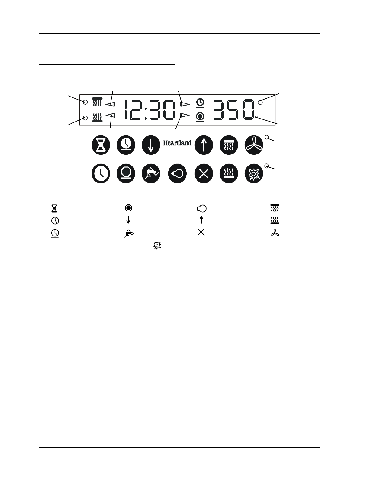
(fig10)
clock
cook time
minute minder
Element “ON”
Indicator
Convection Broil
Indicator
Convection Bake
Indicator
Broil Indicator Start Time Indicator
Stop Time IndicatorBake Indicator
stop time broil
start
increase
decrease
convection
bake
cancel
self clean
oven light
Celsius
Indicator
Self Clean
Indicator
Convection Fan
Indicator
17
Section 4: Oven and Clock Operation
Oven and Clock Operation
secondselapsebetweenconsecutiveselec-
tionsduringprogramming,thefunctionwillbe
cancelledautomatically).
• Timeofdayisalwaysdisplayedin
hours:minutes.
• Themaximumprogrammablelengthoftime
for bake, convection bake, and
minuteminderfunctionsis11hoursand
59minutes.
• Ifsetto 295° F or below, display will show
SP for 5 seconds.
• Afterstartinganycookingfunction,theclock
willdisplay“11:59”instandardmode.
• When using increaseor decreasekeysfor
settingtimes,fastscrollingwillbeginafter
buttonisdepreasedfor5continuousseconds
1. General Information
• Clock must be set before any other
operationoftheelectronicovencontrol.
Noothersettingispossibleuntilthe
clock is set.
• Whensupplyingpowertotheappliancefor
thefirsttimeorafterapowerinterruptionthe
followingwilloccur:
i. Thedigitalclockwilldisplay88:88
ii. The symbolsfor increaseand
decreasewillflashuntiltheclockisset.
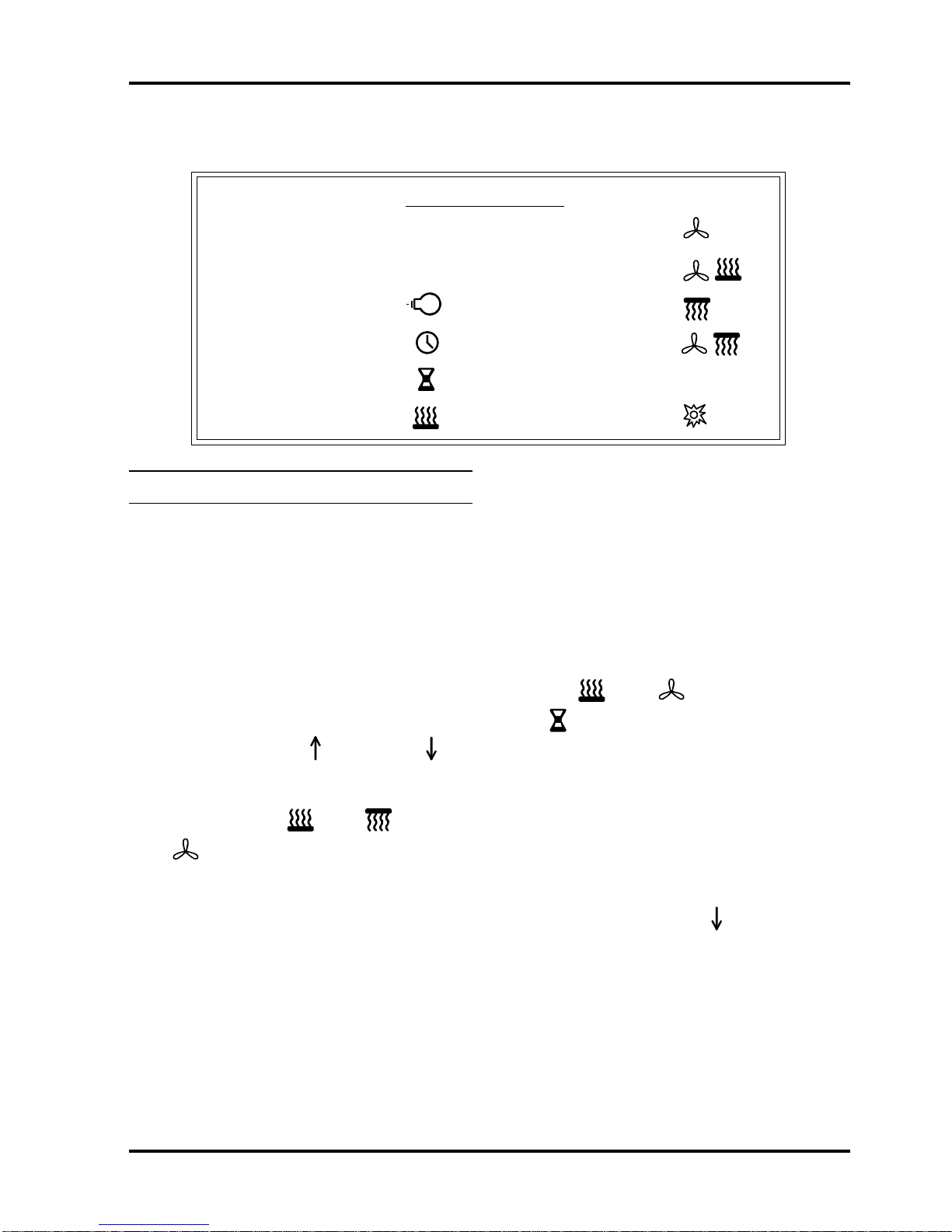
• Oven functions ( bake, broil,
convection,etc.)areidentifiedbya
symbolonthekeypad(fig11).
• Anaudiblesignalwillsoundeachtimea
functionsymbolisfullydepressedandthe
symbolwillcommenceflashing.
• Afteran ovenfunction hasstarted,the
correspondingsymbolwillglowcontinually
untilthefunctioniscompleteorithasbeen
cancelled.
• Programmingoffunctionscanbecancelledat
anytimetobeginagain(ifmorethan20
1. GeneralInformation 7. True Convection
2. SafetyFeatures 8. Convection Bake
3. OvenLight 9. Broil
4. Clock Operation 10.Convection Broil
5. Minute Minder 11. Sabbath Mode
6. Bake 12.SelfClean
Table Of Contents
Other manuals for Legacy 3530
1
This manual suits for next models
6
Table of contents
Popular Cooker manuals by other brands


Hotpoint
Hotpoint HUD 61 Instructions for use and installation

Baumatic
Baumatic PCC1220SS instruction manual

Zanussi
Zanussi ZCV55001WA user manual

Creda
Creda HBD130G Instruction & installation manual

Fagor
Fagor Kore 700 Series Installation, Usage and Maintenance Instructions

Hotpoint
Hotpoint EW32 instructions