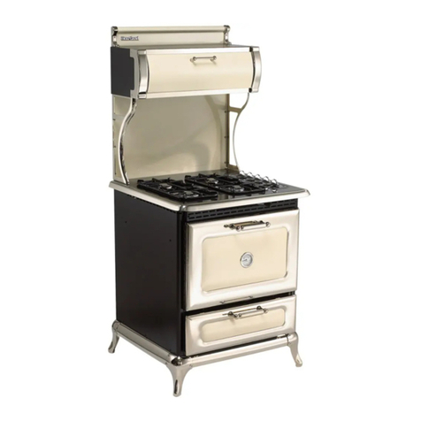
Heartland Appliances 4200 User manual

1050FountainStreetNorthCambridge,Ontario,Canada N3H4R7
Bus.(519)650-5501 Fax(519)650-3773 TollFreePhone1-800-361-1517 TollFreeFax1-800-327-5609
Installation and Operating Instructions For
Models:
Save these instructions
for future use
Note: Please read these instructions thoroughly before attempting to install this unit.
5200 48" Gas Top / Electric Convection Range
5210 48" Gas Top / Electric Convection Self Clean Range
4200 30" Gas Top / Electric Convection Range
4210 30" Gas Top / Electric Convection Self Clean Range
Model
5200/5210
NOTE: Clock must be
set or your main oven
will not function!
Model
4200/4210
ATTENTIONINSTALLER:
Leavethismanualwithappliance
The oven door thermometer does not sense
temperature. It is for aesthestics only and is
nonfunctional.
© 2004 HEARTLAND APPLIANCES INC.
WARNING: Improper installation,
adjustment, alteration, service or
maintenance can cause injury or
property damage. Refer to this manual.
Forassistanceoradditionalinformation,
consult a qualified installer, service
agency, manufacturer (dealer). Please
read these instructions thoroughly
before attempting to install this unit.
Failuretofollowinstallationinstructions
will result in costly service calls.
C
®
US
Manual#5716
042504.013106

!
• ALL RANGES CAN
TIP
• INJURYTOPERSONS
COULDRESULT
• SEEINSTALLATION
INSTRUCTIONS
WARNING
—FOR YOUR SAFETY—
DONOTSTOREORUSEGASOLINEOROTHER FLAMMABLEVAPOURSORLIQUIDSIN
THE VICINITY OF THIS APPLIANCE.
* Do not use the range as a heater.
* Do not heat unopened glass or metal containers in the oven.
*Grease accumulation is the causeof many cooking fires. Clean the oven and broiler compartment regularly.
* Do not attempt to extinguish a grease fire with water. Cover grease fires with a pot lid or baking soda.
*Avoidthe use ofaerosolcontainers near therange.
* Never place pans, cookie sheets or roasters directly on the oven bottom -use the rack in its lowest position.
* Do not cover the entire bottom of the oven with aluminium foil. Allow at least 1" of space all around pots, pans
or cookie sheets in the oven to permit convection air flow.
To move range for service or
cleaning
WARNING
Range body rests on base.
When moving, move by base
only.
1. Disconnectelectricalpower.
2. Place temporary floor protection in front of
range.
3. Slide out from wall and place floor protection
under front legs and slowly pull out to gain
access to rear.
4. Toreinstall,reversetheseinstructions.
The use of a gas cooking appliance results in the
productionofheat and moistureinthe room in whichit
is installed. Ensure that the kitchen is well ventilated:
keepnaturalventilationholesopenorinstallamechanical
device(mechanicalextractorhood)
Prolonged intensive use of the appliance
may call for additional ventilation, for
example opening of a window, or more
effectiveventilation,forexampleincreasing
the level of mechanical ventilation where
present.
WARNING: If the information in this manual is
not followed exactly, a fire or explosion may
resultcausingpropertydamage,personalinjury
or death.
Do not store or use gasoline or other flammable
vapoursandliquidsinthevicinityofthisoranyother
appliance.
WHAT TO DO IF YOU SMELL GAS
• Do not try to light any appliance.
• Do not touch any electrical switch; do not use
anyphone inyour building.
• Immediately call your gas supplier from a
neighbour’s phone. Follow the gas supplier’s
instructions.
• If you cannot reach your gas supplier, call the
firedepartment.
Installation and service must be performed by a
qualifiedinstaller,serviceagencyorthegassupplier.

Gas Top/Electric Convection Models 4200/5200
Gas Top/Electric Convection Self Clean Models 4210/5210
CONSUMER WARRANTY
ENTIRE PRODUCT – LIMITED ONE YEAR WARRANTY
HEARTLANDwarrantsthereplacementorrepairofallparts,includinggascomponentsofthisCookstovewhichprove
to be defective in material or workmanship, with the exception of the painted or porcelain enamel finish or plated
surfaces, for one year from the date of original purchase. Such parts will be repaired or replaced at the option of
Heartland without charge, subject to the terms and conditions set out below.
Thewarrantyperiod against defectsin the paintedorporcelain enamel finish,or plated surfaces,is90 days from
date of original purchase. The warranty does not include replacement of oven lamps or charcoal filters.
OVEN&WARMINGDRAWERELEMENTS-LIMITEDSECONDTHROUGHTHIRDYEARWARRANTY
HEARTLANDwarrantstheovenheatingelementsagainstdefectsinmaterialorworkmanshipforanadditionaltwoyears.
ThesepartswillberepairedorreplacedattheoptionofHeartlandwithoutcharge,butyoupayforlabourandtransportation
subject to the terms and conditions set out below.
TERMS AND CONDITIONS
1. This warranty applies only for single family domestic use when the Cookstove has been properly installed
accordingtotheinstructionssuppliedbyHeartlandandisconnectedtoanadequateandproperutilityservice.
Damage due to faulty installation, improper usage and care, abuse, accident, fire, flood, acts of God,
commercial, business or rental use, and alteration, or the removal or defacing of the serial plate, cancels all
obligationsofthiswarranty. Service during this warrantymustbeperformed by afactoryAuthorizedService
Person.
2. Warranty applies to product only in the country in which it was purchased.
3. HeartlandisnotliableforanyclaimsordamagesresultingfromanyfailureoftheCookstoveorfromservicedelays
beyondtheirreasonablecontrol.
4. Toobtainwarrantyservice,theoriginalpurchasermustpresenttheoriginalBillofSale,ModelandSerialnumber.
Componentsrepairedorreplacedarewarrantedthroughtheremainderoftheoriginalwarrantyperiodonly.
5. Thewarrantydoesnotcoverexpense involved in makingthisappliancereadilyaccessibleforservicing.
6. Thiswarrantygivesyouspecificlegalrights.Additionalwarrantyrightsmaybeprovidedbylawinsomeareas.
7. Adjustmentssuchascalibrations,levelling,tighteningoffasteners,orutilityconnectionsnormallyassociated
with original installation are the responsibility of the dealer or installer and not that of the Company.
TOENSUREPROMPTWARRANTYSERVICE,SENDINYOURWARRANTYCARDWITHIN10DAYSOFPURCHASE.
Iffurther help isneeded concerning thiswarranty, contact:
CustomerService
PLACEOFPURCHASE______________________________
DATEOFPURCHASE_______________________________
SERIALNUMBER__________________________________
MODELNUMBER__________________________________
HeartlandAppliancesInc.
1050 Fountain St. N.
Cambridge,Ontario,Canada
N3H-4R7
Business(519)650-5775
Fax(519)650-3773
TollFreeTelephone1-800-361-1517
TollFreeFax1-800-327-5609

1
TABLE OF CONTENTS
Description ............................... Page
1. Assembly and Installation ...................................... 2
2. Assembly of Exhaust to Range............................. 2
3.Positioning theRange ............................................ 3
4.InstallationClearances ........................................... 3
5. Exhaust Hood ........................................................ 4
6. Ventless Installation ............................................... 4
7.VentedInstallation.................................................. 5
8.ImportantSafetyInstructions.................................. 6
9.OvenSafety............................................................ 6
10.Exhaust Hood Safety............................................ 7
11.SelfCleanOvenSafetyInstructions...................... 7
12.Features (CooktopandRange) withLayout......... 8
13.Features (WarmingDrawer&Storage) ................. 9
14.ClockControlPanel.............................................. 9
15. Control Panel Layout ….....................................10
16.TopBurnerOperation...........................................11
17.PowerFailureOperation ..................................... 12
18.WarmingDrawerControlOperation .....................13
19.Oven BakeBroilControl ......................................14
20.OvenOperation....................................................15
21. How to Select Cooking Methods .........................16
22. Clock / Timer Function ........................................17
23.Time ofDay Setting .............................................17
24. Minute Minder.....................................................17
25. Time Bake..........................................................18
26. Standard&ConvectionCookingGuidelines........19
27.MeatRoastingGuide ...........................................20
28.Poultry RoastingGuide .......................................20
29.BroilingGuide......................................................21
Description ......................................... Page
30.BakingGuide.......................................................21
31.PorcelainCare&Cleaning...................................22
32.StandardOven&WarmingDrawerCleaning........22
33.SelfCleanOvenCleaning ....................................22
34. Howto SelfClean ................................................24
35.TimeDelay SelfClean .........................................25
36.CancelTime Delay Self Clean .............................26
37. Nickel Trim ..........................................................27
38. Exhaust Hood......................................................27
39.ConvectionFanFilter...........................................27
40.OvenandCabinetLight .......................................27
41.SurfaceBurnersCare&Cleaning ........................28
42.Oven&CabinetLightReplacement .....................28
43.InteriorOvenRacks .............................................29
44.RackSupportsRemoval ..................................... 29
45.OvenDoorRemoval .............................................30
46.WarmingDrawerRemoval ...................................31
47.TheBroilerPan....................................................31
48.Setup&TroubleShooting....................................32
49.OvenThermostat .................................................33
50. If you still require help— ......................................33
51.GasTroubleShootingGuide................................34
52.ConversionKitInformation ...................................35
53.BurnerValveOrificeConversion...........................36
54.TopBurnerOrificeConversion .............................36
56.PartsDiagram .....................................................37
57. Parts List.............................................................38
55. Products..............................................................49

2
Assembly and Installation
To fully enjoy your new range, it is important that you read this booklet thoroughly.
Note:
Pleasecheckforanydamagethatmayhaveoccurredduringshipping.Intheunlikelyeventthatyoufindanyshipping
damage,informyourdealerimmediately!
Caution when unpacking:
Lift the range by the bottom skirt, do not lift by nickel trim.
Unpacking:
Note:toavoid injury, pleasewearsafetyequipement, glasses andgloves,while you areunpackingyournew range.
1) Unscrew the 12 screws that hold the crate onto the skid. There are 12 along the bottom and 4 along the top.
2)After the screws have been removed, carefullylift thecrate over the stove and set itaside.
3)Nextwithapairoftinsipscutthemetalbandingthatholdsthestoveintoplace.Cautionmetalbandingisundertension!
4)Carefully remove themetalbanding,the2boardsthatwhereunderthe banding andthecardbordcapandstyrofoam.
5)You are now ready to remove therange fromthe skid
For30"unitshaveonepersonateachendstandbesidetheskidandcarefullylifttherangebythebottomskirt,andathird
person pull the skid out from underneath the range. Slowly set the range down on the floor, bending you knee's not your
back!
For48"unitsunitshaveonepersonateachendandoneside,standbesidetheskidandcarefullylifttherangebythebottom
skirt,andafourthpersonpulltheskidoutfromunderneaththerange.Slowlysettherangedownonthefloor,bendingyour
knee'snot your back!
6)Finish unpacking therangeremovingpackingtapearoundthedoorsand intheoven.
Both 30" and 48" Ranges consist of two main parts:TheRangeBody,and
TheCabinet /Exhaust Hood
Tools required for assembly: -Phillips/RobertsonScrewdriver
- 5/16" ( 8 mm) wrench or crescent wrench
Gliders:
The teflon glider should
extend
beyond the bottom of the leg by approximately
1/8"-1/4". Adjusting levelling bolts in too far will cause the leg to drag on the
floorpotentially causing damage to flooring.(see figure 1). Check that gliders
and floor are free of any debris, this will ensure you do not scratch your floor. Teflon Glider
1/8"- 1/4"
Assembly of Exhaust Hood to Range
Seethemanualentitled"CabinetInstallationInstructions
for Gas, Electric, Combination and Wood Stoves"which
is included with the cabinet .
(DONOTRESTCLOSETCORNERBRACKETSON
PORCELAINSURFACE,DAMAGETOSURFACE
MAYOCCUR)
Figure 1
Figure2
You must have a qualified electrician connect the new range to be sure all electrical codes and rules are
observed except when range is equipped with a cord and plug

3
Positioning the Range
1. Whentherangeis fully assembled, recheck all electrical connections especially between the exhaust hood and theback
of the range. As well, check that all nuts and bolts have been tightened.
2. Ensureteflon glidersand flooring areclean,(as describedonpage 2 under"Gliders").
3. Caution:Onflooringwithveryroughsurfacesordeep,largegroovestheappliancemayhavetobeliftedandslowlyslidinto
position.
4. Put both hands on the trim and carefully push the range into place, make sure floor is clear of all debris.Don't forget to
plug in the main power cord and the exhaust hood power cable and test the operation of the appliance, before the
range is in it's final position. See cabinet installation instructions.
5. To level the range, simply adjust the levelling screws with teflon pads located at the bottom of each leg (the ones you
assembledon page 2under "Gliders"). Usinga 5/16 (8mm)open end wrenchturn theadjustingscrew clockwiseto raise
up thecorner,andcounter-clockwisetolowerthecorner.(Don'tforgettheteflonglidershouldextendbeyondthebottom
of the leg by approximately 1/8"-1/4") Ensure the unit is perfectly level, or utensils may fall of during cooking.
6. Note: Onsoft kitchen flooring,the weight ofthe stovemay cause slightdepressions in theflooring. Whenthe range isin
positionandlevelled,youmaywanttoplacecoastersundertheteflonglidersofeachleg,toprotectthefloor.Removethe
coasterswhenmovingtherangeforcleaningorservicing.
Installation Clearances
Ifthe range muststand besidea refrigerator, it is importantfor proper air circulation, thatthere be at least 5"of space between the
twoappliances.
Donot install rangecloserthan 1/2" fromadjacent surfaces.
Toeliminate theriskofburnsorfireby reachingoverheatedsurfaceunits,installation ofcabinetstoragespace abovethesurface
unitsshould be avoided. If thereis existing cabinet storage space have atleast 30 1/4" (768 mm) ofclearance. (see fig 3)
Forbestcookingresults,yourrangeshouldbelevel.Thiscanbecheckedwithacarpenter’slevelontopofthecookingsurface
andacrosstheovenrack.Iflevellingisrequired,adjustthelevellerscrewsunderoneormoreofthelegs(see"PositioningtheRange"
step 5).
min 18"
457 mm
0
00
min
30 1/4"
768 mm
max
36 "
914 mm
Model 5200 / 5210 48" Installation Clearance
Model 4200 / 4210 30" Installation Clearance
The clearances in the table are also stated on the rating plate and on a reproduction of the plate on
the back page of this manual. (see "installation clearances" diagram)
Installation Clearances
Surfaceadjacent tocooktop-left(48") 1”(25mm) Surface adjacent to cook top-right (48") .......0” (0 mm)
Surface adjacentto cook top(30") 0” (0 mm) Surface adjacent to warming oven ...............0” (0 mm)
Cook topto underside ofadjacent cabinets ... 18”(457mm) Cook top to underside of cabinets .... 30 1/4” (768 mm)
Maximumdepthofoverheadcabinets ............ 13”(330mm) Maximum depth of counters ..................24” (610 mm)
Maximumheight of counters.......................... 36”(914mm) Rearclearance 0” .........................................(0 mm)
Fig 3 Installation Clearances
min 18"
457 mm
0
0
1"
25 mm
min
30 1/4"
768 mm
min
36 "
914 mm

4
Exhaust Hood
Yourrange is equippedwith a twospeed rangehood that maybe either venteddirectly to theoutside, ormay be
installedventless.Asetofexhaustfiltersareincludedwithyourhood.Thefiltersshouldbecleanedperiodicallyin
soapywater.ExtrasareavailablefromyourdealerordirectlyfromHeartlandAppliancesInc.Pleaseorder4ormore
filtersat one time to savefreight and handling charges.
VentlessInstallation
Your unit is already set up for ventless operation. Cooking fumes are drawn through the filters and exhausted
throughthe rearof the hood, back into the room. Install the exhaust filtersin theirlocation under the cabinet by
firstremovingthelightlens.Thenononeside,insertoneofthefiltersintothegrooves(frontandrearofthecabinet)
and slide into place. Repeat these steps for the second filter
Installation of Ducting
Installation through an outside wall
Remove air deflector (used for ventless operation only). Cut a 3 1/2 x 10 1/2 ( 88.9mm x 266.7 mm) hole through
the wall directly behind the range hood outlet (See Figure 4.), making sure no wall studs are cut. Push range into
position.Fromoutsideofthehouse,measuredistancefromthesidingtotherangeoutlet.Cutductpipethatlength,
plus1” (25.4mm)foroverlapintooutlet.Attachventhoodtopipe.Caulkthebackofventhoodandaroundpipewhere
it goes through wall and into range hood outlet so caulking seals against outside siding.
CompleteinstallationbyfollowingdirectionsunderVentlessInstallation.
Installation through an attic to an outside wall
Ifthe vent elbowsareembedded inthewall, the rangemay be positionedas shown inFigure 4. Continuethe duct
through the ceiling into the attic. Terminate duct either on an outside wall just below the sofit using a vent hood or
throughthe roofwith aroof cap.Seal withcaulking aroundand under cap or hood.
CompleteyourinstallationbyfollowingdirectionsunderVentless Installation.
Figure 4
Exhaust venting
options

5
14.0"
355 mm
28”
711 mm
29 1/2”
787 mm
Ran
g
e
Hood
Outlet
3
1/4"x
10"
83
mm
x
254 mm
66 1/4"
1682 mm
62 3/8"
1585 mm
56"
1422 mm
36 1/8"
917 mm
29 3/4"
756 mm
14 7/8"
378 mm
20 "
508 mm
66 1/4"
1682 mm
56 "
1422 mm
36 1/8”
917 mm
47 1/2"
1207 mm
Range Hood Outlet
3 1/4" x 10"
83 mm x 254 mm
39 3/4"
1010 mm
Power
Cord
Exhaust
Hood
In
(female
receptacle)
14.0"
355 mm
28”
711 mm
749 mm
Oven
Exhaust
Gas Inlet-1/2”NPT
4 3/4”
121 mm
30”
762 mm
Installation must be done in
accordancewithalllocaland
nationalcodes.
Use only materials which
conform to local codes in
effect. Be sure power is
disconnected before doing
any electrical work. All duct
work must be metal.
Donotuseplasticduct.The
range hood should never
be exhausted into a wall
cavity or an attic where an
accumulation of grease
could become a fire
hazard.
When the installation is
completed, turn on the fan
andmakesurethatthereare
no obstructions in the duct.
30" Model
48" model
Venting Safety Guidelines
Vented Installation, Tools, Material, and Dimensions
Tools required to install vented hood: -Hammer -Slotscrewdriver
- Pliers - Electric drill
-Measuringtape - 3/32” (3 mm) Drill bit
- 1/2” (13 mm) Drill bit - Sabre saw OR Keyhole saw
Materials Required:
-31/4" x10" (82.55mmx254mm)metalduct—enoughtogothroughwallorattictooutside.Elbowsasrequired.
-Roofcaporwallventhood
- Caulking to seal around duct
- #6 x 1/2” (82.55 mm x 254 mm) sheet metal screws
Theabovearestandardpartsandareavailableatanyhardwarestoreorheatingcontractor.
NOTE
: A 3 1/4" x 10" (82.55mm x 254mm) exhaust adaptor is included with the exhaust hood.
3"
76mm
34"
864mm

6
Important Safety Instructions
1. PROPERINSTALLATION—BESUREYOURAPPLIANCEISPROPERLYINSTALLEDANDGROUNDEDBYA
QUALIFIEDTECHNICIAN.Havetheinstallershowyouthelocationofthecircuitbreakerorfuse.Markitforfuture
reference.
2. Neveruseyourapplianceforwarmingorheatingtheroom.Useonlyforitsintendeduseasdescribedinthismanual.
3. Donotleavechildrenalone.Childrenshouldnotbeleftaloneorunattendedinareawhereapplianceisinuse.Children
should never be allowed to sit or stand on any part of the appliance.
4. Do not allow children to play with controls or any part of appliance.
5. Do not climb, stand or hang on the appliance.
6. Wearproperapparel—loose-fittingorhanginggarmentsshouldneverbewornwhileusingtheappliance.Flammable
material could ignite on contact with hot surface units and cause severe burns.
7. Userservicing—donotrepairorreplaceanypartoftheapplianceunlessspecificallyrecommendedinthemanual.
Allotherservicingshouldbereferredtoaqualifiedtechnician.Beforeperforminganyservice,switchoffcircuitbreaker
orremovefuse.
8. Storage in or on appliance—flammable materials should not be stored in an oven, near surface units or in range
cabinet.
9. Donotusewaterongreasefires–neverpickupaflamingpan-smotherfireorflamebycoveringpanwithawellfitting
lid, cookie sheet, metal tray or use dry chemical or foam type extinguisher.
10. Use only dry potholders—moist or damp potholders on hot surfaces may result in burns from steam. Do not let
potholdertouchhotheatingelements.Donotuseatowelorotherbulkyclothinplaceofpotholder.Suchmaterials
could catch fire on hot surface unit.
11. Do not let cooking grease or other flammable materials accumulate on the cooktop.
Oven Safety
Do not touch heating elements or interior surfaces of oven—heating elements may be hot even though they are
darkin colour. Interiorsurfaces of anoven become hotenough to causeburns.
During and after use, do not touch, or let clothing or other flammable materials to contact heating elements or interior
surfaces of oven until they have had sufficient time to cool.
Othersurfacesoftheappliancemaybecomehotenoughtocauseburns—amongthesesurfacesare,forexample,oven
ventopeningsandsurfacesneartheseopenings,ovendoors.
1. Usecarewhenopeningdoor—lethotairorsteamescapebeforeremovingorreplacingfood.
2. Donotheat unopenedfood containers—buildupof pressure may cause container to burst and resultin injury.
3. Keepovenventductsunobstructed.
4. Placementofovenracks—alwaysplaceovenracksindesiredlocationwhileoveniscool.Ifrackmustbemovedwhile
oven is hot, do not let potholder contact hot heating element in oven.
5. Do not use aluminum foil to linethe bottom of the oven,it could result in a risk of electric shock or fire.

7
Self Clean Safety Instructions
Read the instructions below and the appropriate timer instructions before attempting to operate.
Do not touch heating elements or interior surfaces of oven—heating elements may be hot even though they are dark in
colour.Interior surfacesofanovenbecomehotenoughtocause burns.
Duringandafteruse,donottouch,orletclothingorotherflammablematerialstocontactheatingelementsorinteriorsurfaces
ofoven until they have had sufficient timeto cool.
Othersurfacesoftheappliancemaybecomehotenoughtocauseburns—amongthesesurfacesare,forexample,ovenvent
openingsandsurfacesneartheseopenings,ovendoors.
1.Removeutensilsandcookwarefromtheoven. Ovenracksandracksupportsshouldberemovedfromtheoven.Racksand
supports left in the oven during self clean will become discoloured, but it will not affect the protective coating.
2. Remove all utensils and food from cooktop. Note: use of surface elements while range is self-cleaning is NOT
RECOMMENDED.
3.Removeallcontentsfromthestoragedrawer. Thisincludesplasticoraluminiumutensilsandanyutensilswithplasticparts
thatcanbecomeover heated and melt.
4.In 48" rangesremove all contentsfrom the storagearea . This includesplastic oraluminium utensils andany utensils with
plastic parts that can become over heated and melt.
5. DO NOT clean the gasket. The door gasket is essential for a good seal. Care should be taken not to rub, damage or move
the gasket.
6.Never use a commercial ovencleaner in a self cleaning oven. This willdamage the finish.
7.Makesuretheconvectionfanisoff.Theconvectionfanswitchmustbeturnedoffatthecontrolpanelatthetimer.(The
oven
light
will
automatically go off
when the door is closed.)
Exhaust Hood Safety
Caution: Do not store items of interest to children in cabinet above the range or on top of range cabinet.
Children climbing on range to reach items could be seriously injured.
1. Cleanexhaust hood frequently—grease should not be allowed toaccumulate onhoodorfilter.
2. Iffoodscatch fire underthe hood, turnthe fanoff. The fan,if operating mayspread theflame.
Warming Oven Safety
Caution: Do not store items in the warming drawer, items stored there could be damaged if the warming control
is turned on.

8
Cooking Controls
Thecookingcontrolsarelocatedontheright
hand side of the cooktop; these controls
offer an infinite number of heat settings for
ease and accuracy in cooking and baking.
Sealed Burner Features
A)CentreBurners-aretwomaximum
8,000 BTU (2.34 kW) (L/P
7,000BTU)with simmer of 600
BTU(.2kW)sealedgasburners
,easy clean, for medium duty
cooking tasks
B)LeftBurners- frontsealedburner
is maximum 10,000 BTU (2.93
kW))(L/P9,000BTU)withsimmer
of 1000 BTU (.3 kW) and rear is
maximum 8,000 BTU (2.34 kW)
(L/P 7,000 BTU) with simmer of
600 BTU (.2 kW) accurately
maintaintemperature.
C)RightBurners(48"modelsonly)-
front sealed burner is maximum
10,000 BTU (2.93 kW) )(L/P
9,000BTU)with simmer of 1000
BTU(.3kW)andrearismaximum
8,000 BTU (2.34 kW) (L/P
7,000BTU)with simmer of 600
BTU (.2 kW) , one for large jobs,
oneforsmall,easyclean.
D)GasBurnerControls-allowaninfiniteselectionofcookingtemperatures,4controlson30"modelsand
6controlson48"models.Allmodelsfeature"auto-reignition",whichmeansifforanyreasontheflame
goesout,itautomaticallybeginstospark tore-ignitetheburner!
Oven Features
E)Oventemperaturecontrol-Withbakecontrol,broilcontrol
F) SelfCleanlatchinghandle-slidestotherighttolocktheovendoorduringtheselfcleancycle.(selfclean
modelsonly).Latchmustnotbeusedtolockdoorduringregularcookingfunctionsordamagetolatch
mayoccur.
G)Convectionoven:- baking,broiling
- timedbaking,broiling
- convectionbaking,broiling
- timedconvectionbaking,broiling
- 4positionracking
- 4cubicfeetofenergyefficientbakingarea(.11cubicmeters)
- lowmaintenancehightemperatureselfcleanoven(selfcleanmodelsonly)
Heartland
Heartland
Heartland
Features
B
Control Panel
Burner and
Oven Controls
Figure 5
(48" Model shown)
ACD
Storage
Utensil
Drawer E
F
G
HI

9
Clock Control Panel
Thetimerand control panel is concealed behind thecabinetdoorforstandardandselfcleanmodels.Note:WarmingOvenis
nottimercontrolled
J) Digital Timer - With minute minder and automatic start and stop cooking features.
K)RockerSwitch controls theoverheadlight under theexhausthood.
L)RockerSwitchcontrolsconvectionfanforconvectionbaking/broiling.
M) Three position switch controls the high / low for the exhaust fan. Center position is “OFF”.
Control Panel
A
U
T
O
P
M
J
K
Please Note: Warming oven is not affected by timer settings
L
Warming Drawer Features
H) Located under the main oven, glides open for easy access
- sliding humidity control
-large 1 cubicfoot warming area
I) Thermostatictemperature control, locatedjust right andbehind the warmingdrawer
Storage Features (48" models only)
- Rack storage area: ideal for oven racks and baking trays.
- Utensil drawer: Unique storage space, keeping necessities within easy access

10
Control Panel Layout
The control panel is laid out in a straight line and each control is identified by a
graphic on the right side of the knob.
Theoperationofthecontrolsaredescribed
inthefollowingpages.
Model 4200/4210
Control Panel Model 5200/5210
Control Panel
LeftRearBurnerControl
-Medium
RightRearBurnerControl
-Medium
LeftFrontBurnerControl
-Large
RightFrontBurner Control
-Medium
Bake/BroilOvenControl
(seepage14)
Bake/BroilIndicator Light
WarmingDrawerIndicator
Light(see page 13)
LeftRearBurnerControl
-Medium
LeftFrontBurnerControl
-Large
CentreRearBurnerControl
-Medium
CentreFrontBurnerControl
-Medium
RightRearBurnerControl
-Medium
Bake/BroilOvenControl
(seepage14)
RightFrontBurner Control
-Large
Bake/BroilIndicator Light
WarmingDrawerIndicator
Light(see page 13)

11
OPERATION
TopBurnerControl
6 (HI) - Quick start for cooking, brings water to
boil.
5(MEDHI)-Fastfry,panbroil,maintainfastboil
onlargeamountoffood.
4(MED)-Sauteandbrown;maintainslowboilon
largeamountoffood.
3(MEDLOW)-CookafterstartingatMAX;cook
withlittlewater in coveredpan.
2-1(LOW)-Steamrice,cereal;maintainserving
temperatureofmostfoods.
Top Burner Operation
Lighting the Top Burners
Your range is equipped with a spark ignition system that is electrically operated. You need only to push in and turn the knob
toany position andthe burnerwill light. Whenyou turn theknob, youwill hear adistinct clickingnoise. After theburner lights,
theclickingnoisewillstop.Note:whenlightinganyoneburner,allburnerswillspark,butonlytheburnerthatyouhaveselected
willlight.Allmodelsfeature"auto-reignition",whichmeansifforanyreasontheflamegoesout,itautomaticallybeginstospark
tore-ignitetheburner!
Seepage 12for manuallighting procedure.
For safety reasons, always adjust the burner controls so that flames do not extend beyond the
edges of pots, pans or other cooking utensils.
Large pots or other over sized cooking utensils may cause random sparking from the burner. To
avoid this condition lower the flame size or use smaller sized cooking utensils.
Do not use a griddle directly on top of grates. To avoid random sparking, please use the Heartland
Griddle Pan Kit for Classic Ranges part #7602 (complete with griddle pan support) may be
purchased from your dealer or directly from Heartland.

12
Power Failure Operation
Ifelectricalpowerisinterruptedinyourarea,youcanstillcookmealsonthetopburnersofyour
Heartlandgas /electricrange.Of courseyour ovenwill beinoperable,however,byfollowing
thesesimpledirectionsyouwillbeabletousethetopburnerswithoutthebenefitofelectricity.
Caution:makesureyourhandsandclothingareclearoftheburneryouarelighting!
Manually Lighting the Top Burners
1)Removecastgrate,forunobstructedaccesstotheburnerhead.
2)Holdaflamesourcetothedesiredburnerhead.Werecommendabarbecuelightertouse
asa flamesource.
3)Pushinandturnthecorrespondingcontrolknobtothemediumsetting.
4)Aftertheburnerlights,adjustflamesizeasrequired.
5)Carefullyreplacecastgrate, keepfingersclearoftheflame.
Please note that the "auto reignition" feature will not function without electricity,
thereforepaycloseattentiontoanyburnersinusewhileelectricalpowerisinterrupted!
Whenlightingtopburnersmanually,set
controltothemediumsettingtoprevent
potential injury from the flame when
replacingthegrate.
TopBurnerControl

13
Heartlan
d
H
eartla
n
Hear
tlan
Closed
Open
Warming Drawer Control and Operation
To activate the warming drawer, first find the temperature control located
beside the warming drawer behind the drawer door.
Select a temperature level from low to high.("-" to "+) The temperature is
infinitely variable and ranges from 130°F to 220°F. (54°C to 104°C)
When the control is in use the indicator will glow until the temperature level
has been reached, then it will cycle on and off to maintain temperature.
Warm rolls,breads,vegetables,meatsetc.
aswell asplates onHIGH.
Thewarming draweralso featuresa humidity
controllocated alongthetop ofthe drawer
door.When the controlis positionedtothe
leftstop, thehumidity isretainedinthewarm-
ingdrawer. If positionedto therightstop,
thenair isableto circulateallowing humidity
to escape.
Tookeepmoisture in,close humiditycontrol.To keepthings crisp,openhumidity control.Proof (rise)
breador pizzadoughonLOWwith humiditycontrol closed
Pleasenote: Donot usethedrawer asstorage.Items storedtheremay bedamagedif thetemperature
controlisactivated. Warming drawer maybe removed foreasier cleaning(see"Warming Drawer
Removal" page 31")
warming oven indicator light located right
and below main oven control
temperature control
humidity control
sliding warming drawer

14
Bake - Broil Control
Baking
To bake, push down and turn the oven control counter clockwise to any desired temperature.
When baking is selected, the indicator light under the bake symbol lights up, and the bake
elementwillactivate.Theelementwillthencycleonandofftomaintainanaveragetemperature
intheoven
Pleasenote:
thatwhenovenisturnedontopreheat,thefirstcyclemayexceedsettemperature
-pleaseallowoventocycleon/offbeforeplacingfoodinoven.
Thetemperatureisinfinitelyvariablebetweentemperatures 150°Fand 550°F(65°Cand290°C.)
Broiling (do not broil with door open)
Toactivatebroil(topelement),turnovencontroltobroil.Whenbroilingisselected,theindicator
light, lightsup.Tode-selectbroiling,turntheovencontrolknobtoatemperaturesetting,which
resetsthecontroltobaking mode. If knobisturnedpastthe "BROIL" position -elementwillnot
operate.Turnback to broilposition.
Oven Bake/ Broil Control
Main oven
indicator light Warming drawer
indicator light

15
Oven Operation
BeforeYoustart:
1. Remove the oven racks and oven rack supports and clean with soap and water. (see
interior oven rack
and
rack support
removal pg. 29 ).
2. Unwrapbroiler panand clean with soap and water.
3. Cleanovenwithsoapandwater,makingsurethatalladhesiveshavebeenremoved.
4. Settimeontheclock,clockmustbesetorovenwillnotfunction!(seetimersection
pg.17).
5.Turn ovenonto500°F(260°C)for30minutestoburnoffbondingagentsintheinsulation.
Therewillbeanunpleasantodourand some smoke, which isunavoidable.
Getting to Know Your Oven
Theovenlightwillautomaticallyactivatewhentheovenisopenedanddeactivatewhenthe
ovendoorisclosed.
Alsoiftheovenissetforconvectionmode,thentheconvectionfanwilldeactivatewhenthe
ovendoor is opened, andactivatewhentheovendoorisclosed.
Theovenfeaturesmultilevelregularbaking/broilingintimedorun-timedmodes. Forenergy
efficientbatchbaking,chooseconvectionbaking,whichallowsyoutobakeonmultilevels
simultaneously. Fortraditional baking the convection featureshould beOFF.
Yourovenhasatemperaturerangeof150°Fto550°F(65°Cto290°C).TheovenCycling
Lightglowsuntilovenreachesthehighendofheatingcycle,thencyclesoffandonduring
cooking.Theaverageofthehighandlowlevelsoftheheatingcycleswillbeapproximately
within30°Fofselectedtemperature.Thistemperaturefluctuationisnormalandstandard
intheapplianceindustry.Seepages19and21forrecommendedbakingandroastingtimes
andtemperatures.
Note:
1)SelfCleanModelsOnly-Donotengagetheselfcleanovendoorlatchwhennotin
selfclean mode, as it is possibletheoven door safety interlock willactivateat high
oventemperatures and damage could occur tothe locking mechanism.
2)See pages20 through 21 for recommended broil times and settings.
3)Temperaturesinovensmayshiftovertimeanditisnaturalfortheusertograduallyadapt
cookingtimesaccordingly.Then,whenbakinginanewovenwithpropercalibration,results
maynotbeasexpectedbasedonpreviousbakinghabits.Ovencavitysizesalsovaryfrom
manufacturer to manufacturer and could affect cooking results slightly. Therefore, it may
takesometimetofamiliarizeyourselfwithyournewovenandsomeadjustmentincooking
times may be necessary.

16
How to Select Cooking Methods
StandardBaking-Tobake,turntheovencontroltoanydesiredtemperaturebetween150°Fto500°F(65°CAND290°C).
When baking is selected, the indicator lights up, and the bake element will activate. Always preheat the oven
approximately5-10minutes.Duringcooking,thebakeelementwillcycleonandofftomaintaintemperatures. Donot
rotate control past 500°F (290°C) for bake as this is the broil position and only top element will come on.
Standard Broiling - To activate broil (top element), turn oven control to broil (end stop position). When broiling is
selected, the indicator lights up. At this setting the broil element comes on and stays on. To de-select broiling,
turntheovencontrolknobtoatemperaturesetting,whichresetsthecontroltobakingmode. Whenbroiling,theoven
doorshouldremainclosed,andthegreasefilterinstalled.Pleasedonotleavefoodunattendedwhilebroilingasitmay
smokeorevenburn.
Convection - when the rocker switch in the exhaust hood is set to this symbol, the convection fan has been
activated. Theconvectionfan can be operated in three modes.
1) convectionbaking.
2) convectionbroiling.
3) convectiondrying.
Note: When using convection baking, please ensure the grease filter is
not
installed, otherwise, air will
not be able to properly circulate in the oven. Filter must be installed for convection broiling/roasting.
ConvectionBaking- select a temperature on the oven control and then select " " below the rocker switch.
Ovenisnowin"ConvectionBake Mode".
Convection Broiling - select "broil" on the oven control and select " " below the rocker switch. The oven
needs to remain closed while in Convection Broil Mode. When broiling, please take care not to leave food
unattended as it may smoke or burn.
ConvectionDrying-leavetemperaturecontrolat"OFF"andselect" "belowtherockerswitch. Theconvection
fan has been activated and oven is now ready to dry spices or fruits.
For time bake, when the rocker switch is set to this symbol " " and the timer and temperature controls are set,
the fan will then automatically activate when the selected time has been reached. For more detail on "Time Bake"
see page 18.

17
Adjust setting down
Duration of bake or S/C time
"Auto" indicates auto
activatetimerinoperation
Bell symbol indicates minute
minderinoperation
Minuteminder Adjust setting up
Endbakeor S/C time Initiate/Cancel
Setup
Cookingsymbol
indicates oven is in
auto shut off time
bakemode
CLOCK/ TIMER
Time of Day Setting
NOTE: Clock must be set or your main oven will not function!
1. To set the time of day:
a) the clock read-out will be flashing "0:00"and "
AUTO
" alternately.( at first time set up or after a power failure)
b) press " " and " " buttons simultaneously to activate the clock time adjustment. The display will stop flashing
except for the ""
AUTO
" symbol. You will have 3 seconds to start the next step.
c)tap" "toadvancetime,or " " to decreasetime,thedisplaywillbegin at "12.00".Pressandhold to advance time
quickly. Set to the correct time of day (the clock is based on a 12 hr cycle).
d) once the time of day has been entered, the clock is set and the appliance is ready to use.
e)timeofdaymaybeadjustedatanypointbypressingthe" "and" "buttonsandthenpressing" "or" "setting
buttons.
MinuteMinder
1. To set timer: (the minute minder can be at any time even when in timer modes)
a) press “ “ the minute minder button.
b) Set the timer in minutes using the " " and “ “ setting buttons.
c) The timer activates 5 seconds after the setting buttons are released, and returns to dime of day mode.
d) when the set time has been reached the timer will sound, 2 distinct beeps.
e) to see time remaining on timer press “ “ at any time.
A
U
T
O
TIMER
STOP
STOP
This manual suits for next models
3
Table of contents
Other Heartland Appliances Range manuals
Heartland Appliances
Heartland Appliances U109760-02 User manual

Heartland Appliances
Heartland Appliances Legacy 3530 User manual
Heartland Appliances
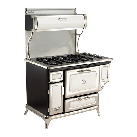
Heartland Appliances 5200 User manual

Heartland Appliances
Heartland Appliances Metro User manual
Heartland Appliances
Heartland Appliances 9100 User manual

Heartland Appliances
Heartland Appliances Legacy 3630 User manual
Heartland Appliances
Heartland Appliances 7100 User manual

Heartland Appliances
Heartland Appliances 3825 User manual


