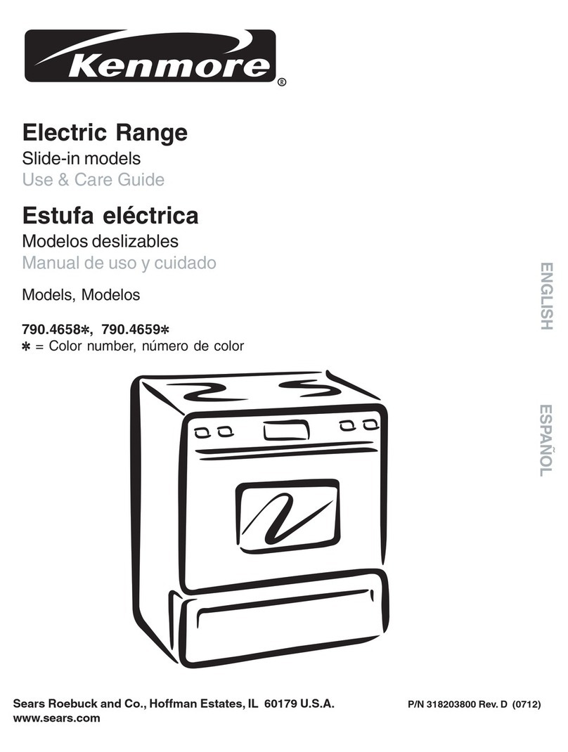
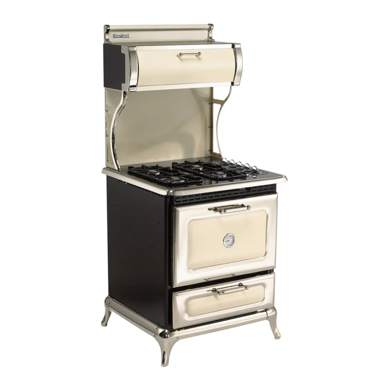
Heartland Appliances 7100 User manual

MODEL 9100/7100
GAS RANGE
ATTENTION INSTALLER:
Leave this manual with appliance
INSTALLATION
AND
OPERATING
INSTRUCTIONS
Save these
instructions
for future use
Note: Please read these instructions
thoroughlybeforeattemptingtoinstall
thisunit. WARNING: Improper installation, adjustment, alteration, service or
maintenance can cause injury or property damage. Refer to this
manual.Forassistanceoradditionalinformation,consultaqualified
installer, service agency, manufacturer (dealer) or the gas supplier.
Note
: This appliance can only be installed in the state of
Massachusetts by a Massachusetts licensed plumber or gasfitter.
The oven door thermometer does not sense temperature. It is for
aesthestics only and is nonfunctional.
Model
9100
Model
7100
Manual#7715
REV111204
© 2004HEARTLANDAPPLIANCESINC.
1050 Fountain St. N.
Cambridge,Ontario,Canada N3H4R7
Bus.(519)650-5501 Fax(519)650-3773
TollFreePhone1-800-361-1517
TollFreeFax1-800-327-5609
These symbols on the nameplate mean the product has been
designcertifiedbyAmericanGasAssociation Laboratoriesand
CanadianGasAssociationLaboratories.
C
CERTIFIED
®
US

Gas Models 9100/7100
CONSUMER WARRANTY
ENTIRE PRODUCT – LIMITED ONE YEAR WARRANTY
HEARTLANDwarrantsthereplacementorrepairofallparts,includinggascomponentsofthisCookstovewhichprove
to be defective in material or workmanship, with the exception of the painted or porcelain enamel finish or plated
surfaces, for one year from the date of original purchase. Such parts will be repaired or replaced at the option of
Heartland without charge, subject to the terms and conditions set out below.
Thewarrantyperiodagainstdefects in the painted or porcelainenamel finish,or platedsurfaces, is90 daysfrom
date of original purchase. The warranty does not include replacement of oven lamps or charcoal filters.
TERMS AND CONDITIONS
1. This warranty applies only for single family domestic use when the Cookstove has been properly installed
accordingtotheinstructionssuppliedbyHeartlandandisconnectedtoanadequateandproperutilityservice.
Damage due to faulty installation, improper usage and care, abuse, accident, fire, flood, acts of God,
commercial, business or rental use, and alteration, or the removal or defacing of the serial plate, cancels all
obligationsofthiswarranty. Serviceduring this warranty must be performed by a factory Authorized Service
Person.
2. Warranty applies to product only in the country in which it was purchased.
3. HeartlandisnotliableforanyclaimsordamagesresultingfromanyfailureoftheCookstoveorfromservicedelays
beyondtheirreasonablecontrol.
4. Toobtainwarrantyservice,theoriginalpurchasermustpresenttheoriginalBillofSale,ModelandSerialnumber.
Componentsrepairedorreplacedarewarrantedthroughtheremainderoftheoriginalwarrantyperiodonly.
5. Thewarranty does not cover expense involved inmakingthisappliancereadilyaccessibleforservicing.
6. Thiswarrantygivesyouspecificlegalrights.Additionalwarranty rightsmaybeprovidedbylawinsomeareas.
7. Adjustments such as calibrations, levelling, tightening of fasteners, or utility connections normally associated
with original installation are the responsibility of the dealer or installer and not that of the Company.
TOENSUREPROMPTWARRANTYSERVICE,SENDINYOURWARRANTYCARDWITHIN10DAYSOFPURCHASE.
Iffurtherhelp is needed concerning thiswarranty, contact:
CustomerService
HeartlandAppliancesInc.
1050 Fountain St. N.
Cambridge,Ontario,
Canada N3H4R7
PLACEOFPURCHASE______________________________
DATEOFPURCHASE_______________________________
SERIALNUMBER__________________________________
MODELNUMBER__________________________________
Business(519)650-5775
Fax(519)650-3773
TollFreeTelephone1-800-361-1517
TollFreeFax1-800-327-5609

!
• ALL RANGES CAN
TIP
• INJURYTOPERSONS
COULDRESULT
• SEEINSTALLATION
INSTRUCTIONS
WARNING
—FOR YOUR SAFETY—
DO NOT STORE OR USE GASOLINE OR OTHER FLAMMABLE VAPOURS OR
LIQUIDS IN THE VICINITY OF THIS APPLIANCE.
* Do not use the range as a heater.
* Do not heat unopened glass or metal containers in the oven.
* Grease accumulation is the cause of many cooking fires. Clean the oven and broiler compartment
regularly.
* Do not attempt to extinguish a grease fire with water. Cover grease fires with a pot lid or baking
soda.
*Avoidtheuseofaerosolcontainers near the range.
* Never place pans, cookie sheets or roasters directly on the oven bottom -use the rack in its lowest
position.
* Do not cover the entire bottom of the oven with aluminium foil. Allow at least 1" of space all around
pots, pans or cookie sheets in the oven to permit convection air flow.
To move range for service or
cleaning
WARNING
Range body rests on base.
When moving, move by base
only.
1. Disconnectelectricalpower.
2. Place temporary floor protection in front of
range.
3. Slide out from wall and place floor protection
under front legs and slowly pull out to gain
access to rear.
4. Toreinstall,reverse theseinstructions.
Theuseofagascookingappliance results
in the production of heat and moisture in
the room in which it is installed. Ensure
that the kitchen is well ventilated: keep
natural ventilation holes open or install a
mechanical device (mechanical extractor
hood)
Prolonged intensive use of the appliance
may call for additional ventilation, for
example opening of a window, or more
effectiveventilation,forexampleincreasing
the level of mechanical ventilation where
present.
WARNING: If the information in this manual is
not followed exactly, a fire or explosion may
resultcausingpropertydamage,personalinjury
or death.
Do not store or use gasoline or other flammable
vapoursandliquidsinthevicinityofthisoranyother
appliance.
WHAT TO DO IF YOU SMELL GAS
• Do not try to light any appliance.
• Do not touch any electrical switch; do not use
anyphone in yourbuilding.
• Immediately call your gas supplier from a
neighbour’s phone. Follow the gas supplier’s
instructions.
• If you cannot reach your gas supplier, call the
firedepartment.
Installation and service must be performed by a
qualifiedinstaller,serviceagencyorthegassupplier.


1
TABLE OF CONTENTS
1. Assembly and Installation.................................. 2
2. Assembly of Range Base...................................... 2
3. Assembly of Range Body to Base......................... 3
4. AssemblyofExhaustHoodtoRange.......................4
5. Positioning the Range ........................................... 4
6. Installation Clearances .......................................... 5
7. Electrical and Gas Installation............................... 6
8. Exhaust Hood ...................................................... 7
9. Ventless Installation.............................................. 7
10.VentedInstallation ................................................ 7
11.InstallationofDucting.............................................8
12.Venting Safety Guidelines .................................... 9
13.GasLineInstallation................................................9
14.ImportantSafetyInstructions ...........................10
15.Exhaust Hood Safety...........................................10
16.Features .............................................................11
17.SealedBurnerFeatures.......................................11
18.OvenFeatures .....................................................12
19.OtherFeatures ................................................... 12
20.ControlPanelLayout .......................................... 13
21. Operation...........................................................14
22.TopBurnerOperation...........................................14
23 Oven Lighting......................................................15
24.RangeThermostat.................................................15
25PowerFailureOperation .......................................16
26.ManuallyLightingtheTopBurners.......................16
27.ManuallyLightingtheOvenBurner.........................16
28.Clock/Timer..........................................................17
29. Care and Cleaning............................................18
30.Porcelain .............................................................18
31.OvenCleaning .....................................................19
32.SurfaceBurners...................................................19
33. Nickel Trim ..........................................................20
34. Exhaust Hood......................................................20
35.OvenandCabinetLight .......................................20
36.InteriorOvenRackRemoval.................................21
37.RackSupportsRemoval ..................................... 21
38.OvenDoorRemoval .............................................22
39. Broiling................................................................23
40. BroilingPan.........................................................23
41. OvenLight............................................................23
42.BroilerDrawerRemoval .......................................24
43. Setup and Trouble Shooting ...........................25
44.BurnerSetup and Adjustment .............................25
45.RangeProblemSolver .........................................25
46. Air Shutter Adjustment ........................................26
47. Oven Burner Assembly.......................................26
48.TroubleShootingGuide .......................................27
49. Conversion Kits and Information...................28
50. Products ............................................................29
51.Products .............................................................31
52. Parts Diagram ...................................................32
53.PartsList ............................................................33
54.RatingPlate.........................................................34
55. Wiring Diagrams ...............................................35

2
Assembly and Installation
To fully enjoy your new range, it is important that you read this booklet thoroughly.
Note:
Please check for any damage that may have occurred during shipping. In the unlikely event that you find any shipping
damage,informyourdealerimmediately!
TheModel 7100 and9100 Range consists ofthree main parts:
TheRangeBase
TheRangeBody,and
TheExhaust Hood or CrestingAssembly
Painted section
Figure1
Assembly of Range Base
1. Unpackagethebasesections,legsandhardwarepackagewhichare locatedinacartonfastenedtotheskid
atrearoftherange(itwouldbeagoodideatocheckforanydamagethatmayhaveoccurredduringshipping).
2. Screwthe baselevellingbolts(withteflongliderattached)intoeachofthefourlegs.The levelling bolts are
locatedinthehardwarepackage.Wheninstallingthelevellingbolts,theteflonglidershould
extend
beyond
thebottomofthelegbyapproximately1/8"-1/4". Adjustinglevellingboltsintoofarwillcausethelegtodrag
onthefloorpotentiallycausingdamagetoflooring.(seefigure1a) . Checkthatglidersandfloorarefreeof
any debris, this will ensure you do not scratch your floor.
3. Assemblebasetolegsusingthenutsandboltsprovided.Forthe48"theshorterbasesectionsarethesides
andthelongersectionsarefrontandrear.(theblackpaintedsectiongoestotherear,seefig.1).Forthe30"
the base sections are all the same length, the black painted section goes to the rear, see fig. 1.
4. Handtightenthenutsandboltsuntiltherangebaseiscompletelyassembled.Ensurethatallbasesections
are installed with the lip up.
5. Adjust base sections to the most upper position and tighten up the nuts and bolts.
Nickel plated section
Figure 1a
Teflon
Glider
Teflon Glider
1/8"- 1/4"
Tools required for assembly:
Slotscrewdriver
7/16”(11mm)wrench orcrescentwrench
5/16"(8mm) wrench or crescentwrench
(You must have a qualified gas technician install this appliance to be sure
the installation codes and rules are observed.)

3
Assembly of Range Body to Base
Lift the range at the front and rear,
do not lift by nickel trim.
1. Therangebodyrestsdirectlyonthe base - noboltsarerequired.Twopeople are needed to liftiton
to the base.
2. Inordernottodamagethenickeltrimorenamelfinish,lifttherangefromthefrontandtherear.The
personatthefrontcanfirstremovetheovendoorandusetheovenopeningfora handhold.Therear
of the oven body at the bottom can be used to lift from the back.
3. Lifttherangeoffpalletandontobase,makingsuretherangeissittingsquareandlevelonbase.The
stovesits over the lip of the base assembly. Helpfulhint:Insteadoftryingtosquaretheentirestove
over the base, put one side or back on first then slowly lower the other side into position.
4. Lastly, install the oven vent deflector on the top of the cooking surface over the oven vent. Loosen
the two screws enough to slip the oven vent under the screws , and tighten up the screws. (see
illustrationbelow)
Loosen two screws Oven vent deflector
Oven vent

4
Positioning the Range
1. When the range is fully assembled, recheck all electrical connections especially between the
exhausthoodandthebackoftherange.Aswell,checkthatallnutsandboltshavebeentightened.
2. Ensure teflon gliders and flooring are clean, (as described in the second paragraph under
"Assemblyof RangeBase".)
3. Caution:Onflooringwithveryroughsurfacesordeep,largegroovestheappliancemayhavetobe
liftedandslowlyslidintoposition.
4. Putboth hands onthe trimand carefullypush therange into place,make surefloor isclear ofall
debris. Don't forget to plug in the main power cord and the exhaust hood power cable
before the range is in its final position. Seecabinetinstallation instructions.
5. Toleveltherange,simplyadjustthelevellingscrewswithteflonpadslocatedatthebottomofeach
leg(theonesyouassembledinstep2of"AssemblyofRangeBase").Usinga5/16 (8mm)open-
endwrenchturntheadjustingscrewclockwisetoraiseupthecorner,andcounter-clockwisetolower
thecorner.(Don'tforgettheteflonglidershould
extend
beyondthebottomofthelegbyapproximately
1/8"-1/4")
6. Note: Onsoftkitchenflooring,theweightofthestovemaycauseslightdepressionsintheflooring.
Whentherangeisinpositionandlevelled,youmaywanttoplacecoastersundertheteflongliders
of each leg, to protect the floor. Remove the coasters when moving the range for cleaning or
servicing.
Assembly of Exhaust Hood to
Range
Seethemanualentitled"CabinetAssembly
Instructions for Gas , Electric
,Combination and Wood Stoves" which
is included with the cabinet .

5
Installation Clearances
Iftherangemuststandbesidearefrigerator,itisimportantforproperaircirculation,thattherebeatleast
5" of space between the two appliances.
Do not install range closer than 1/2" from adjacent surfaces.
Toeliminatetheriskofburnsorfirebyreachingoverheatedsurfaceunits,installationofcabinetstorage
space abovethesurfaceunitsshouldbeavoided.Ifthereisexistingcabinetstoragespacehaveatleast
30" of clearance. (see fig 3)
For best cooking results, your range should be level. This can be checked with a carpenter’s level
ontopofthecookingsurfaceandacrosstheovenrack.Iflevellingisrequired,adjustthelevellerscrews
under one or more of the legs (see "Positioning the Range" step 4).
min 18"
457 mm
0
0
1"
25 mm
min
30 1/4"
768 mm
min
36 "
914 mm
min 18"
457 mm
0
00
min
30 1/4"
768 mm
max
36 "
914 mm
Model 7100 Installation Clearance
Model 9100 Installation Clearance
Fig 3 Installation Clearances
The clearances in the table are also stated on the
ratingplate andonareproductionof theplateonthe
back page of this manual. (see "installation
clearances"diagramFig.3)
Installation Clearances
Surfaceadjacenttocook top-left(7100).............. 1”(25mm)
Surfaceadjacenttocooktop-right(7100) ............ 0” (0 mm)
Surfaceadjacenttocooktop(9100) .................... 0” (0 mm)
Surfaceadjacenttowarmingoven........................ 0” (0 mm)
Cook top to underside of adjacent cabinets ... 18”(457mm)
Cook top to underside of cabinets.............30 1/4” (768 mm)
Maximumdepthofoverheadcabinets ............ 13”(330mm)
Maximumdepthof counters .......................... 24”(610mm)
Maximumheightof counters.......................... 36”(914mm)
Rearclearance..................................................... 0” (0 mm)

6
Cabinetpowerhook-up
Figure5
maleend of the
cabinetpowercordfemalereceptacle
Exhaust Hood Electrical Connection
After your exhaust hood has been installed the very last thing to do is to connect the special plug to the range. The
femalereceptacle for the exhausthoodislocatedattherear of the stove bythemainpower(male)receptacle (See
page 8 for receptacle locations and figure 5 for receptacle illustration). Simply plug the cabinet power cord into the
receptacle, be sure to test all functions of the cabinet.
Electrical Installation
THEMODEL7100/9100GASRANGEMUSTBEELECTRICALLYGROUNDEDINCOMPLIANCEWITHLOCAL
CODESANDINTHEABSENCEOFLOCALCODES,WITHTHENATIONALELECTRICALCODEANSI/NFPA
70“LATESTEDITION”INTHEU.S.ORTHECANADIANELECTRICALCODE,PARTI,CSASTANDARDC22.1
INCANADAorYOURNATIONALELECTRICALCODE
Connectthe female endof the powercord to themain power (male) receptacleat the rearof the stove.See page 8for
receptaclelocations and figure 4forreceptacleillustration
Thisrangemustbepluggedintoaproperlygrounded/earth, receptacle.Thegrounding/earthprongmustnotberemoved,
fromtheplug.DISCONNECTTHEELECTRICALSUPPLYBEFORESERVICINGTHEAPPLIANCE.
The receptacle to be used for this appliance must be wired to STANDARD WIRING PRACTICES.
malereceptacle femaleendof
thepowercord
Mainpowerhook-up
Figure4

7
Exhaust Hood
Yourrangeis equipped with atwospeedrange hood that maybe eitherventeddirectly to the outside, ormaybe
installedventless.Asetofexhaustfiltersareincludedwithyourhood.Thefiltersshouldbecleanedperiodicallyin
soapywater.ExtrasareavailablefromyourdealerordirectlyfromHeartlandAppliancesInc.Pleaseorder4ormore
filtersatonetimetosavefreightandhandlingcharges.Phoneyour dealer for pricing and ordering instructions.
VentlessInstallation
Yourunitisalreadysetupforventlessoperation.Cookingfumesaredrawnthrough thefiltersandexhaustedthru
therearofthehood,backintotheroom.Installtheexhaustfiltersintheirlocationunderthecabinetbyfirstremoving
thelight lens. Then on one side, insert one ofthefiltersintothegrooves(frontandrearofthecabinet) and slide
into place. Repeat these steps for the second filter
Figure 6
Exhaust venting
options
.
Vented Installation, Tools, Material, and Dimensions
Tools required to install vented hood:
Hammer Slotscrewdriver
Pliers Electric drill
Measuringtape Drill bits
SabresawORKeyholesaw
Materials Required:
Duct—enough to go through wall or attic to outside. Elbows as required.
Roofcaporwallventhood
Caulking to seal around duct
Sheet metal screws
Theabovearestandardpartsandareavailableatanyhardwarestoreorheatingcontractor.

8
Installation of Ducting
Installation through an outside wall
Removeairdeflector(usedforventlessoperationonly).Cutappropriate-sizedholethroughthewalldirectlybehind
the range hood outlet (see Figure 6 ,page 7), making sure no wall studs are cut. Push range into position. From
outsideofthehouse,measuredistancefromthesidingtotherangeoutlet.Cutductpipethatlength,plus1"(25mm)
foroverlapintooutlet.Attachventhoodtopipe.Caulkthebackofventhoodandaroundpipewhereitgoesthrough
wall and into range hood outlet so caulking seals against outside siding.
Completeinstallation byfollowingdirectionsunderVentlessInstallation.
Installationthroughanattic
to an outside wall
If the vent elbows are
embedded in the wall, the
range may be positioned as
shown in Figure 6. Continue
the duct through the ceiling
intothe attic.Terminateduct
either on an outside wall just
below the sofit using a vent
hoodorthroughtheroofwith
aroofcap.Sealwithcaulking
aroundandundercaporhood.
Completeyourinstallationby
following directions under
VentlessInstallation.
Model 9100
Model 7100
19"
483
mm
66
1/4"
1682
mm
56
"
1416
mm
36
1/8"
917
mm
9 ¼"
235
mm
Range
Hood
Outlet:
3
1/4"
x
10"
83
mm
x
254mm
Power
In
(
8 ft (2.4m) cord supplied
direct
con ect)
Exhaust
Hood
In
(female
recepticle)
1
1/4
"
32
mm
29
3/4
"
756
mm
31.0"
787
mm
14"
356
mm
38 1/4"
72 mm9
47 1/2"
1207 mm
33/4"/92mm
Range Hood
Outlet : 3 1/4"x 10"
83 mm x 254mm
34 "
864 mm
36 1/8"
917 mm
29 3/4"
756 mm
62 3/8"
1585 mm
66 1/4"
1682 mm
147/8 "
378mm
Exhaust
HoodIn
56"
1422 mm
14.0"
356 mm
29 3/4 "
756 mm
31.0"
787 mm
Power In
(
8 ft (2.4m) cord
supplied
direct connection)
2"
51 mm
Gas Inlet-1/2 NPT
29 3/4"
756 mm

9
Venting Safety Guidelines
Installationmustbedoneinaccordancewithalllocalandnationalcodes.Useonlymaterialswhichconformtolocalcodes
ineffect.Besurepowerisdisconnectedbeforedoinganyelectricalwork.Allductworkmustbemetal.Donotuseplastic
duct.Therangehoodshouldneverbeexhaustedintoawallcavityoranatticwhereanaccumulationofgrease
could become a fire hazard.
When the installation is completed, turn on the fan and make sure that there are no obstructions in the line.
Gas Line Installation
TheModel 7100 /9100canbeoperated on eithernaturalgasorliquid propane (LP) and are set for naturalgas OR
propane(LP)gasatthefactory.Besureyourrangeiscorrectlyinstalledbyaqualifiedservicemanorinstallerforthe
type of gas on which it is to be used.
Whenpreparingtoinstallthe9100,beawarethatthereareseveralalternativelocationsforthegassupplypipetoenter
intothestove.Forreasonsofappearanceyoumaywanttoconcealthegassupplypipe,andthiscanbeachievedby
routingthesupplypipethrough knockoutslocatedontherearoratthebottomofthestove(seeillustrationbelow).To
usethealternativelocations,thebackpanelmustbedisassembledandtheselectedknockoutremoved.Routethepipe
throughtheknockoutanduptothemanifold.Reassemblethebackpaneltothestove.Model7100hasonlyonesupply
pipeinstallation location. (see illustration below)
THERANGE MUST BEINSTALLED IN COMPLIANCE WITHLOCAL CODES, ANDIN THE ABSENCE OFLOCAL
REQUIREMENTS,THEINSTALLATIONMUSTCONFORMWITHTHENATIONALGASCODE.
Note
: Appliances installed in the state of Massachusetts:
- This appliance can only be installed in the state of Massachusetts by a Massachusetts licensed plumber or
gasfitter
- This appliance must be installed with a three (3) foot / 36 inch long flexible gas connector
- A “T” handle type manual gas valve must be installed in the gas supply line to this appliance
THEAPPLIANCEMUSTBEISOLATEDFROMTHEGASSUPPLYPIPINGSYSTEMBYCLOSINGITSINDIVIDUAL
MANUALSHUTOFFVALVEDURINGANYPRESSURETESTINGOFTHEGASSUPPLYPIPINGSYSTEMATTEST
PRESSURES EQUAL TO OR LESS THAN 3.5 KPS (1/2 PSIG).
Themaximumpropane/naturalgassupplyinletmustnotexceed14inchesofwatercolumn.Theminimumgassupply
inlet should be at least 5 inches of water column for natural gas or at least 11 inches of water column for LP gas.
Gas Inlet on manifold
All electrical
components
behind panel. Knock-outs for gas
piping behind back
panel.
Knock-outs for
gas piping in
bottom panel.
5 7/8
149 mm
4 1/2
115mm
3 3/4
95 mm
9 1/2
240 mm
13 3/4
350mm
34
864 mm
5 1/4"
133 mm
30"
762 mm
10"
254 mm
Gas Inlet to manifold
9100 optional gas inlet locations 7100 optional gas inlet location

10
Important Safety Instructions
1. PROPERINSTALLATION—BESUREYOURAPPLIANCEISPROPERLYINSTALLEDANDGROUNDEDBY
AQUALIFIEDTECHNICIAN.
2. NEVER use this appliance as a space heater to heat or warm the room. Doing so may result in Carbon
Monoxidepoisoningandinoverheatingoftheoven.
3. Donotleavechildrenalone.Childrenshouldnotbeleftaloneorunattendedinareawhereapplianceisinuse.
They should never be allowed to sit or stand on any part of the appliance.
4. Wearproperapparel—loose-fittingorhanginggarmentsshouldneverbewornwhileusingtheappliance.
5. User servicing—do not repair or replace any part of the appliance unless specifically recommended in the
manual.All other servicingshouldbereferredto a qualified technician.
6. Storageinoronappliance—flammablematerialsshouldnotbestoredinanoven,nearsurfaceunitsorinrange
cabinet.
7. Donot use water on grease fires—smotherfire or flame or use dry chemical orfoam-type extinguisher.
8. Use only dry potholders—moist or damp potholders on hot surfaces may result in burns from steam. Do not
let potholder touch hot heating elements. Do not use a towel or other bulky cloth.
9. NEVERcoveranyslots,holesandpassagesintheovenbottomorcoveranentirerackwithmaterialssuchas
aluminumfoil.DoingsoblocksairflowthroughtheovenandmaycauseCarbonMonoxidepoisoning.Aluminum
foil linings may also trap heat, causing a fire hazard.
10. ItisagoodpracticetoinstallCOdetectorswhenanygasapplianceorfurnaceispresentinthehome. Please
followmanufacturer’srecommendationsforlocationandinstallationofCOdetectors.
Exhaust Hood Safety
Caution: Do not store items of interest to children in cabinet above the range or on top of range cabinet.
Children climbing on range to reach items could be seriously injured.
1. Cleanexhausthoodfrequently—greaseshouldnot be allowedtoaccumulateonhoodor filter.
2. Whenflaming foods under thehood,turnthefanoff.Thefanifoperatingmayspreadtheflame.
Oven Safety
Donot touch heating elementsor interior surfaces ofoven—heatingelementsmaybe hoteventhoughthey
aredarkincolour.Interiorsurfacesofanovenbecomehotenoughtocauseburns.Duringandafteruse,donottouch,
orletclothingorotherflammablematerialstocontactheatingelementsorinteriorsurfacesofovenuntiltheyhave
hadsufficienttimetocool.Othersurfacesoftheappliancemaybecomehotenoughtocauseburns—amongthese
surfacesare,forexample,ovenventopeningsandsurfacesneartheseopenings,ovendoors.
1. Usecarewhenopeningdoor—lethotairorsteamescapebeforeremovingorreplacingfood.
2. Donotheatunopenedfoodcontainers—buildupofpressuremaycausecontainertoburstandresultininjury.
3. Keepovenventductsunobstructed.
4. Placementofovenracks—alwaysplaceovenracksindesiredlocationwhileoveniscool.Ifrackmustbemoved
while oven is hot, do not let potholder contact hot heating element in oven.

11
Cooking Controls
Thecookingcontrolsarelocatedontherighthandsideofthecooktop;thesecontrolsofferaninfinitenumberofheat
settings for ease and accuracy in cooking and baking.
Sealed Burner Features (see fig. 7)
A) Centre Burners - are two maximum 8,000 BTU (2.34 kW)(L/P 7,000 BTU) with simmer of 600 BTU (.2 kW)
sealed gas burners,easy clean, for medium duty cooking tasks.
B) Left Burners - front sealed burner is maximum 10,000 BTU (2.93 kW) (L/P 9,000 BTU) with simmer of 1000
BTU (.3 kW) and rear is maximum 8,000 BTU (2.34 kW)(L/P 7,000 BTU) with simmer of 600 BTU (.2 kW)
accuratelymaintaintemperature.
C) Right Burners (48" models only) - front sealed burner is maximum 10,000 BTU (2.93 kW) (L/P 9,000 BTU)
withsimmer of 1000 BTU(.3kW)andrearis maximum 8,000 BTU(2.34kW)(L/P7,000BTU) with simmerof
600 BTU (.2 kW) , one for large jobs, one for small, easy clean.
D) GasBurnerControls-allowaninfiniteselectionofcookingtemperatures,4controlsonmodel9100and6controls
on model 7100. All models feature "auto-reignition", which means if for any reason the flame goes out, it
automatically begins to spark to re-ignite the burner!
A
Features
C
BD
Figure 7
E
F
H
I
J

12
Oven Features
E)OvenTemperatureControl-Withinfinitebaketemperatureandbroilcontrol.Allunitsfeature"autogasshutoff",
which means that if for any reason the flame goes out, gas to the oven burner shuts off!
F)GasOvenFeatures: -baking
-3position racking
-2 cubic feet of energy efficient area (.05 cubic meters)
-13,500BTU(3.96Kw)ovenburner
Other Features (see fig. 8)
G) Digital Clock - With minute minder.
H)Broiler - Broilerdrawer located underthe oven, glides open for easy access,for all yourbroiling needs.
I) More Storage - (model 7100 only) lift and open the cast door to gain access to more storage area.
J)CabinetDoor-theminuteminder,exhaustfancontrolandoverheadlightswitchareconcealedbehindthecabinet
door.
K) Three position switch - Controls high and low for exhaust fan centre position is “OFF”.
L) On -off switch - controls overhead light in exhaust hood.
L
K
G
Fig. 8

13
Model 7100
Control Panel The control panel is laid out in a straight line
and each control is identified by a graphic on
the right side of the knob.
Theoperationofthe controls
aredescribedinthe following
pages.
Control Panel Layout
Model 9100
Control Panel
Left Rear Burner
Control(Medium)
Right Rear Burner
Control(Medium)
Left Front Burner
Control (Large)
Centre Front Burner
Control (Medium)
Centre Rear Burner
Control (Medium)
Right Front Burner
Control(Large))
Oven Control Oven Control
Right Front Burner
Control(Medium)
Left Front Burner
Control (Large)
Right Rear Burner
Control(Medium)
Left Rear Burner
Control(Medium)
5
6
4
3
0
2
1
5
6
4
3
0
2
1
5
6
4
3
0
2
1
5
6
4
3
0
2
1
200
350
170
300
145
250
120
95
235
205
400450
F
C
265
50
5
6
4
3
0
2
1
5
6
4
3
0
2
1
5
6
4
3
0
2
1
5
6
4
3
0
2
1
5
6
4
3
0
2
1
5
6
4
3
0
2
1

14
OPERATION
Top Burner Control
6 (HI) - Quick start for cooking, brings water to
boil.
5(MEDHI)-Fastfry,panbroil,maintainfastboil
on large amount of food.
4(MED)-Sauteandbrown;maintainslowboilon
large amount of food.
3(MEDLOW)-CookafterstartingatMAX;cook
with little water in covered pan.
2-1(LOW)-Steamrice,cereal;maintainserving
temperatureof mostfoods.
Top Burner Operation
Lighting the Top Burners
Yourrangeisequippedwithasparkignitionsystemthatiselectricallyoperated.Youneedonlytopush
inandturntheknobtoanypositionandtheburnerwilllight.Whenyouturntheknob,youwillheara
distinctclickingnoise.Aftertheburnerlights,theclickingnoisewillstop.Note:whenlightinganyone
burner,allburnerswillspark,butonlytheburnerthatyouhaveselectedwilllight.Allmodelsfeature
"auto-reignition",whichmeansifforanyreasontheflamegoesout,itautomaticallybeginstospark
tore-ignitetheburner!
Seepage16 formanuallighting procedure.
Forsafety reasons,alwaysadjust theburnercontrolssothatflamesdonot extendbeyond
the edges of pots, pans or other cooking utensils.
Large pots or other over-sized cooking utensils may cause random sparking from the
burner. To avoid this condition lower the flame size or use smaller-sized cooking utensils.
Do not use a griddle directly on top of grates. To avoid random sparking, please use the
Heartland Griddle Pan Kit for Classic Ranges part #7602 (complete with griddle pan
support) may be purchased from your dealer or directly from Heartland.
3
2
0
1
5
6
4

15
Oven Cooking
OvenLighting
Openovendoor.Thereare2holesintheovenbottomsoyoucanviewtheovenflame.Push
inandholddowntheovenknobandselectthedesiredoventemperature.Youshouldhear
sparking until the oven flame ignites. You must continue to keep oven knob depressed
for 5-6 seconds after the oven ignition has occurred. The extra 5-6 seconds is to heat up
the safety thermocouple to allow proper oven control. (releasing the knob too early will
extinguish the flame) All units feature flame sensing auto shutoff, so if for any reason the
flame goes out, the gas supply to
the oven is shut off automatically!
Pleasenote:thefirsttimetheoven
isused,theovenlightingprocedure
mayhavetoberepeated2-4times
topushoutanyairin the gaslines.
Ifthe ovenflame
does not light
in
10 seconds, STOP. Release oven
knob, this will prevent any further
gas from going into the oven. Wait
at least 1 minute before trying to
light oven again. If you are still not
successful see "trouble shooting
guide".
Range Thermostat
The temperature in the oven is
transmitted to the thermostat by
thesensor tubelocated at therear
of the oven. It must always be in
position on its mounting clips and
should not be bent. The sensor
causes the burner to maintain the
desired oven temperature.
Broil
Whenbroiling,theovencontrolknobshouldbesetat550°F(290°C).Theovendoorshould
bepositionedatthefirststoppositiononthedoorhinge,whichwillleavethedooropenapprox.
5inches.Ifthedoorisclosedduringbroiling,thetemperatureintheovencouldreach550°F,
causingtheovenburnertocycledowntothe"lowposition",whichwilleffectyourbroilingtime.
Oven Control Knob
205
400
300
170
350
145
200
250
120
95
C
F
0
450
235
500
265

16
Power Failure Operation
Ifelectrical powerisinterruptedin your area,youcanstill cookmealsonyourHeartland gasrange.Byfollowing thesesimple
directions you will be able to use the burners and oven without the benefit of electricity.
Caution:make sure your handsand clothing are clearof the burner youare lighting!
Manually Lighting the Top Burners
1) Removecast grate, forunobstructedaccessto the burner head.
2) Holda flame sourcetothedesired burner head.
We recommend a barbecue lighter to use as a flame source.
3) Push in and turn the corresponding control knob to the medium setting.
4) Carefully replace cast grate, keep fingers clear of the flame.
5) After the burner lights, adjust flame size as required.
Please note that the "auto reignition" feature will not function without electricity, therefore pay close attention to
any burners in use while electrical power is interrupted!
TopBurnerControl
When lighting top burners manually, set control to the
medium setting to prevent potential injury from the
flame when replacing the grate.
Manually Lighting the Oven Burner
The oven can be operated safely by lighting the oven burner in the following
manner:
1. Removetheovenbottom.
2. Holdaflamesourceatthefrontoftheburnerdirectlybesidetheigniter.We
recommendabarbecuelighterasflamesource.
3. Pushinandholddowntheknob,continuetoholddowntheovenknoband
selectthedesiredoventemperature.
4. You must hold oven knob down for at least 10 seconds after ignition, to
activate the oven safety thermocouple. (releasing the knob too early will
extinguishtheflame).
5. Iftheovenflame
doesnotlight
in10seconds,STOP.Releaseovenknob,
this will prevent any further gas from going into the oven. Wait at least 1
minute before trying to light oven again. If you are still not successful see
"troubleshootingguide".
6. Place oven bottom back onto position, Caution keep fingers and clothing
awayfromtheflame!
Please note that the flame sensing auto shutoff feature
is still functional
without the benefit of electricity so
if for any reason the flame goes out, the gas supply to the oven is shut off automatically!
When lighting oven burner manually, light the burner
at the igniter. Keep hands and clothing away from
open flame!
OvenBurner and
Igniter
This manual suits for next models
1
Table of contents
Other Heartland Appliances Range manuals
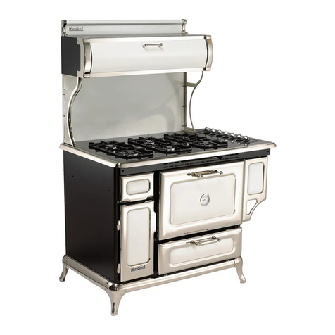
Heartland Appliances
Heartland Appliances 5200 User manual

Heartland Appliances
Heartland Appliances Legacy 3530 User manual
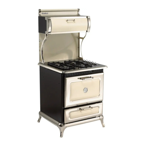
Heartland Appliances
Heartland Appliances 9100 User manual
Heartland Appliances
Heartland Appliances U109760-02 User manual

Heartland Appliances
Heartland Appliances 3825 User manual

Heartland Appliances
Heartland Appliances Legacy 3630 User manual
Heartland Appliances
Heartland Appliances 4200 User manual

Heartland Appliances
Heartland Appliances Metro User manual
