Heartland Appliances Legacy 3530 User manual
®
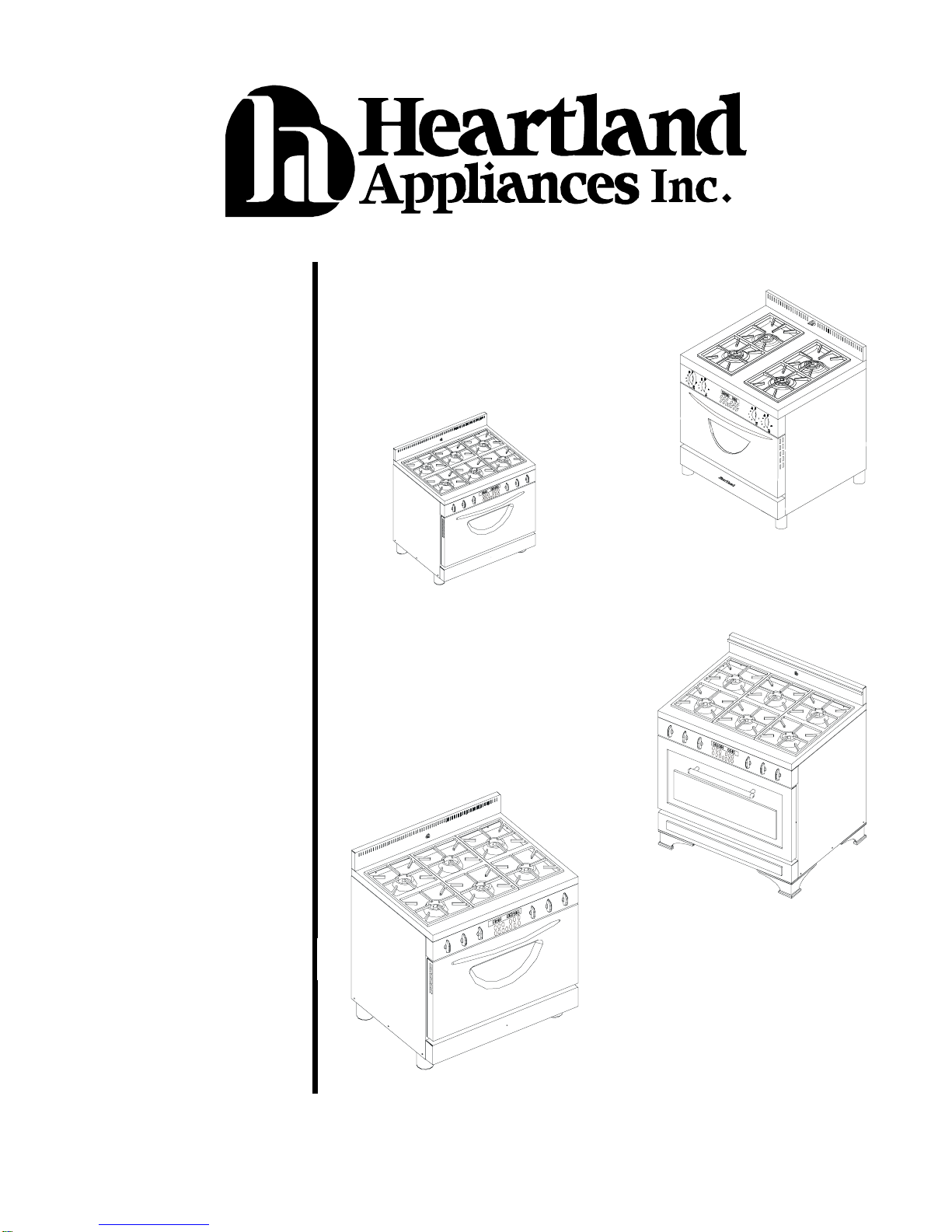
METRO LEGACY
SERIES II
SERVICE MANUAL Model 3530
30” Legacy
Model 3535
30” Metro
Model 3630
36” Legacy
Model 3635
36” Metro
Diagnosis Charts
Service Procedures
Component Data
Heartland Appliances Inc.
Manual No. MLSM2003-09-03
0910-1

MLSM2003-09-03Part# 0910-1 2
RepairManualforHeartlandAppliancesInc
Metro& Legacy Ranges
2003, September 3 HeartlandAppliancesInc.
1050FountainSt. N
Cambridge,Ontario;N3H 4R7
Allrights reserved. Nopart of thisbook may bereproduced in
anyformorbyanymeanswithoutwrittenpermissionfromHeartland
We have used all possible care to ensure the accuracy of
the information contained in this book. However, Heart-
land assumes no liability for any errors, omissions or any
defects whatsoever in the diagrams and/or repair proce-
dures or for any damage or injury resulting from utiliza-
tion of said diagrams and/or repair procedures.
Safety Information: Electric and Gas Ranges are complex
electromechanical devices. Any attempt to repair a range
may, if improperly performed, result in personal injury or
property damage. Heartland Appliances cannot be re-
sponsible for the interpretation of this manual, nor can it
assume any liability in connection with its use. For addi-
tional safety information, see page 5 of this manual.

3MLSM2003-09-03
Contents
Section 1: Safety Information ............................4
Section 2: Parts and Warranty ..........................5
Section 3: Technical Specifications ....................7
Section 4: Problem Diagnosis Chart ..................8
PleaseRefertoMainServiceManual
MLSM010601.
Amendment is intended to illustrate
changes made to the location of the relay
board and the new clock.
Section 5: Repair Procedures ........................... 9
A -Terminal Block 9
B-TimerReplacement 10
C-TimerProgramming 11
D - Broil Element 12
E - Self Clean Latch Mechanism 13
F-Timer Relay Board 14
G-TimerCoaxialCable 15
H-Cooling Fan & Thermodisk 16
I-Spark Module 17
J-RegulatorReplacement 18
K-GasConversion 19
L-Burner Caps 21
M - Electrodes 22
N-BurnerValves 23
O - Back Panel Access 24
P - StoveTop Prop Up 25
Section 6: Wiring Diagrams .............................26
Models3530/3535 26
Models3630/3635 27
Section 7: Exploded Views and Parts List ........28
NOTE: FORFULLSERVICENOTES,PLEASEREFER
TOSERVICEMANUAL#0910

Section 1
4MLSM2003-09-03
Safety Information
Important Safety Notice
HeartlandAppliances’Service
Manuals are intended for use by
individuals possessing
electrical, gas and mechanical
experience. Therefore,
Heartland Appliances cannot be
responsible for the interpretation
of its Service Manuals by those
not having a background of
electrical, gas and mechanical
experience, nor can it assume
any liability in connection with
their use.
Safe Servicing Practices
To preclude the possibility of
resultant personal injury and/or
property damage, it is imperative
that safe servicing practices be
observed. The following are
examples, but without limitation,
of such safe practices:
1. Before servicing, always
disconnect the product from
its source of electrical power
by removing the product’s
electrical plug from the wall
receptacle or tripping the
circuit breaker to OFF(or
removing the fuse) in the
branch circuit servicing the
product.
Note: If a specific diagnostic
check requires electrical
power to be applied such as
for voltage or amperage
measurements, reconnect
electrical power only for time
required for specific check,
and disconnect power
immediatelythereafter.
During any such check,
ensure no other conductive
parts, panels or yourself
come into contact with any
exposed current carrying
parts.
3. If a replacement part is
required ensure it meets
factory specifications.
4. Never by-pass or interfere
with the proper operation of
any feature, part or device
engineered into the product.
5. Prior to reconnecting
electrical power service to
the product, ensure that:
a) all electrical
connections
within the product
are correctly and
securely
connected,
b) all electrical
harness leads
areproperly
dressed and
secured away
from sharp
edges, high
temperature
components
(heaters, etc.)
and moving
parts,
c) any un-insulated
current-carrying
metal parts are
secured and
spaced
adequately from
all non-current-
carrying metal
parts,
d) all electrical
grounds (internal
and external to
the product) are
correctly and
securely
connected, and
e) all access panels
and covers are
properlyand
securely
assembled
followingthe
servicing and
prior to operating
the product.
6. On gas appliances, do not
disturb gas-carrying
components or connections
until gas service to it is shut
off, and do not use a flame
to test for gas leaks.
Following repair work,
ensure all gas connections
are properly secured by
testing for gas leaks with a
bubble (soap) solution.
7. Do not attempt a repair if you
have any doubts as to your
ability to complete it in a safe
and satisfactory manner.

Section 2
5MLSM2003-09-03
Parts & Warranty
HowTo Obtain Parts:
•Contact an authorized
Heartland dealer or Heartland
Appliances direct.
•When ordering replacement
parts (warranty or not) always
provide the following
information:
Serial Number
Model Number
Component Description
Part number
•Commonly replaced parts are
listed in Section 7 at the end of
this book and at the back of the
owner’s manual.
•To obtain replacement parts
directly from Heartland, contact
the following departments:
Heartland Appliances Inc.
1050 Fountain St. N.
Cambridge, Ontario
N3H 4R7
ph: 877-650-5775
fx: 800-327-5609
Warranty & Non-Warranty
Replacement Parts:
Service Dept. Ext. 2241 & 2264
Note: Please contact Heartland
Appliances Service Department
prior to performing service work in
order to assist in the diagnosis of
the problem, this should result in
having to go to the customer’s
home only once.
How To Set Up Warranty Service:
•Contact one of the
manufacturer’s service
technicians to obtain a CSF
reference number. CSF
numberwillserveasauthoriza-
tiontoproceed with warranty
workandwillbereferencedfor
anyfuturewarrantywork.
ContactHeartlandAppliances
ServiceDepartmentat:
Heartland Appliances Inc.
1050 Fountain St. N.
Cambridge, Ontario
N3H 4R7
ph: 877-650-5775
fx: 800-327-5609
Service Department:
Extensions 2241 & 2264
•CSF number to be referenced
in all warranty claims
•ContactingHeartland
Appliances prior to performing
service work, will assist in the
diagnosis of the problem, this
should result in having to go to
the customer’s home only
once.
How To Submit Warranty Claims:
•For prompt warranty claim
processing, submit your
standard service form (i.e.
Narda style) completely filled
out to:
Heartland Appliances Inc.
Service Department
1050 Fountain St. N.
Cambridge, Ontario
N3H 4R7
fx:800-327-5609
•Warranty Claim forms to in-
clude, but not limited to, the
followinginformation:
•CustomerName,Addressand
PhoneNumber
•SerialNumber
•Model Number
•Date of Service
•Work Performed
••
••
•Full Description of Work
Performed
••
••
•CSF Reference number (see
“How To Set Up Warranty
Service” section above for
details).
How to Return Merchandise:
•Contact Heartland Appliances’
Service Department to obtain
authorization for any
merchandise returns at:
Heartland Appliances Inc.
1050 Fountain St. N.
Cambridge, Ontario; N3H
4R7
ph: 877-650-5775
fx: 800-327-5609
Service Department:
Extensions 2241 & 2264
•Depending on the nature of the
merchandise to be returned, an
RGA number (Return Goods
Authorization) may be issued.
A comprehensive RGA Kit
package will be expedited with
instructions and back up
paperworkforthepromptand
safereturnofthe goods.
Section 2
6MLSM2003-09-03
Parts & Warranty
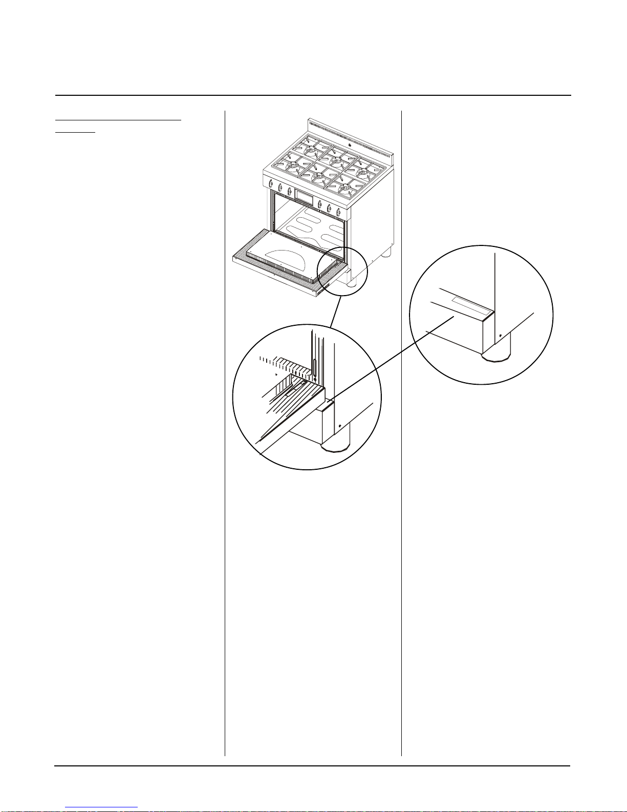
Serial Number Location in
Ranges:
•Metro & Legacy ranges have
the serial number located at the
back of the range and on the
kick plate.
To view serial number plate,
open door, and look at
kickplate’s right top corner.
(view shown with door removed)

Section 3
7MLSM2003-09-03
Technical Specifications
Dual Fuel Ranges (Electric Oven
& Gas Top)
•30”Models3530/3535
240V, 60Hz, 4.1 Kw (3 prong or
4 prong)
Bake Element: 3400 W
Broil Ribbon Element: 4000 W
Conv. ring element: 2400 W
Natural Gas (6” w.c.)
Propane (11”w.c.)
½” NPT (5/8” flex line)
Surface Burners (4):15,500 Btu
Note: Service Amperage to be
calculated by a qualified
electrician.
•36”Models3630/3635
240V, 60Hz, 5.6 Kw (3 prong or
4 prong)
Bake Element: 5000 W
Broil Ribbon Element: 5000 W
Conv. ring element: 4800 W
Natural Gas (6” w.c.)
Propane (11”w.c.)
½” NPT (5/8” flex line)
Surface Burners (6):15,500 Btu
Note: Service Amperage to be
calculated by a qualified
electrician.
•36”Models with Grill
3630B/3635B
240V, 60Hz, 5.6 Kw (3 prong or
4 prong)
Bake Element: 5000 W
Broil Ribbon Element: 5000 W
Conv. ring element: 4800 W
Natural Gas (6” w.c.)
Propane (11”w.c.)
½” NPT (5/8” flex line)
Surface Burners (4):15,500 Btu
Grill Burners (2): 7,500 Btu
Note: Service Amperage to be
calculated by a qualified
electrician.
Electrical Requirements:
•Standard 240V; 60 Hz
receptacle,properly polarized,
on its own dedicated line must
be used.
•Ranges are provided with a
molded plug cap power cord
rated at 120/240 Volts.
•Ranges must be electrically
grounded in compliance with
local codes. In absence of
local codes, the installation
must conform with the National
Electrical Code.
Gas Requirements:
•During any pressure testing of
the gas supply piping system at
test pressures equal to or less
than 2.5 kps, the appliance
must be isolated from the gas
supply system by closing its
individual manual shut off valve.
•The maximum propane/natural
gas supply inlet pressure must
not exceed 14” of water column
•Gas ranges must be installed in
compliance with local gas
codes. In absence of local
codes, the installation must
conform with the National Gas
Code.

8MLSM010601
Section 4
Problem Diagnosis Charts
Models 3530/3535; 3630/3635 & 3630B/3635B
PLEASE REFER TO
SERVICE MANUAL #0910
FOR FULL TROUBLE
SHOOTING GUIDE
DETAILS
THIS AMENDMENT IS
INTENTED TO
ILLUSTRATE CHANGES
MADE TO THE LOCATION
OF THE RELAY BOARD,
CLOCK MOUNTING, AND
ASSOCIATED
COMPONENTS.
F2code Doornot locked during self clean
Problem PossibleCause Repair/Test Procedure
StuckDoor Latch (Procedure E)
Check Wire from Door lock to Clock
(ProcedureE)
F3 code High Limit Tripped in clock Faulty Clock (ProcedureB)

Section 5
9MLSM2003-09-03
Procedure A
- Terminal Block
Step 1:
Disconnect power supply to
range.Pullrangeawayfromwall
andremovebackguardheldby3
screwsandwashers.
Step 2:
PropTop Up.See Proce-
dure P. Inspect top terminal block
forburntterminal connections. If
damaged,replace.Ifnopower to top
terminal, check terminal block at
power cord connection.Seebelow.
Step 3:
To replace back of stove
terminalblock,removepowercord
by unscrewing the three screws that
retain the ends of the cord to the
terminalblock.
Step 4:
Mark and disconnect all
wires attached to the terminal block
(includingwireto ground stud for 4
prongpowercords)
Step 5:
Terminal block can be
removedfromrangebyremovingthe
two center screws.
Step 6:
Install new terminal block,
attach all red, white and black wires
asoriginallymarked
Step 7:
Attach power cord back on
terminal block. Be sure all wires are
secure. 3prongpowercordshave
jumper cable from center (neutral)
side of terminal block to stud. 4
prong power cords have copper
wire from cord directly attached to
groundstud.
Step 8:
To replace top of stove
terminal block, disconnect wires to
terminal block and repeat steps 3
through7.

Section 5
MLSM2003-09-03
10
Procedure B
- Timer Replacement
Step 1:
For oven to operate, time of
day must be set in timer. See Timer
Programming(ProcedureC)for
details.
Step 2:
Disconnect power supply to
range.Pullrangeawayfromwall
andremovebackguard.SeeProce-
dure A Step 1.
Step 3:
PropTop Up.See Proce-
dure P.
Step 3:
Remove4screwsholding
timertocontrol panel and transfer
wires to new clock.
Step 4:
Disconnect coaxial power
supply cable by lifting both locking
tabs.
Step 5:
Disconnect two molex
plugs from clock. Please note that
clock has specific markings for
eachmolex plug: a)solenoiddoor
“lock” has a smooth grey wire and
is attached to the left side of the
clockand b) oven “probe” withhigh
temperature shield is connected to
the right side of the clock.
Note: Ifthesewiresareversed,
code F1 will be display as soon as
any cooking function is selected.
Step 6:
Transfer all wires to the
new timer in the exact same loca-
tion.
Note: Whenre-attachingthe coaxial
computer cable, please ensure it is
fully inserted and that both locking
tabsaresecurelyengaged.
Section 5
11 MLSM2003-09-03
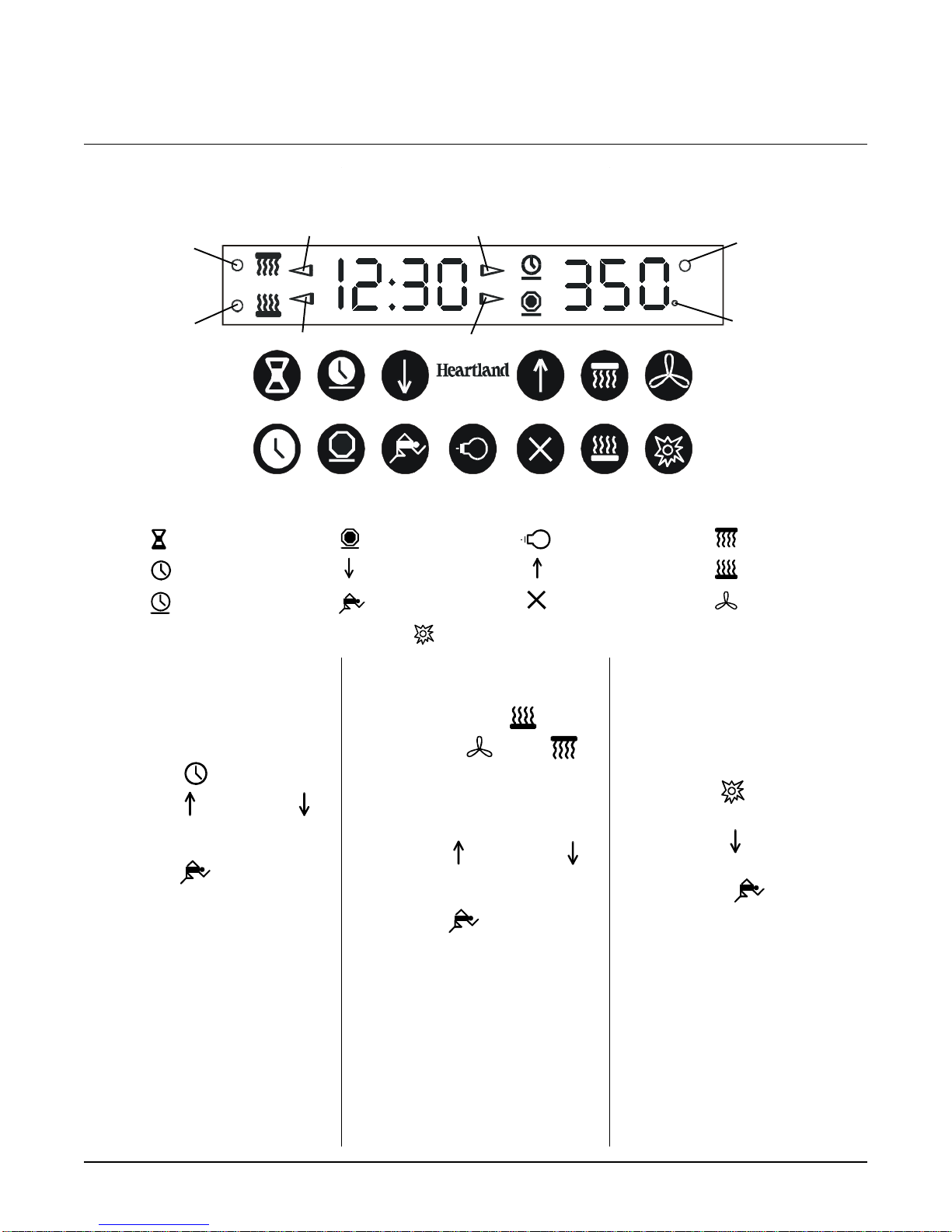
Procedure C
- Timer Programming
Step 1:
For oven to operate, time
of day must be set in timer.
Step 2:
Press
clock
symbol
Step 3:
Press
increase
or
decrease
symbols to select
time
Step 4:
Press
start
symbol to
set
Note: Pressing twice the clock
symbol toggles time of day
between 0-12 hrs and 0-24
hrs
Step 5:
To set cooking, press
desired function (bake ,
convection bake or broil ).
Note:
automatically sets to 325F for
bake and convection bake and to
550F for broil.
Step 6:
Press
increase
or
decrease
symbols to select
time
Step 7:
Press
start
symbol to
start.
Note:To toggle between Fahrenheit
(F) and Celcius (C), press
cooking symbol twice in a
row.
Self Clean Programming: all
cookware, racks, and rack supports
to be removed from oven during
self clean cycle to prevent them
from becoming dull and blue-gray.
Step 8:
Press
self clean
symbol (automatically set for 3 hrs)
Step 9:
Press
decrease
cleaning time.
Step 10:
Press
start
symbol
to begin
self clean.
Note: A thermostatically controlled
cooling fan will start shortly
after the self clean cycle is
programmed (once the door
is locked). The fan will
automatically shut off when
the self clean cycle is
finished and the unit is
sufficientlycool
clock
cook time
minute minder
Element “ON”
Indicator
Convection Broil
Indicator
Convection Bake
Indicator
Broil Indicator Start Time Indicator
Stop Time IndicatorBake Indicator
stop time broil
start
increase
decrease
convection
bake
cancel
self clean
oven light
Celsius
Indicator
When finished ensure probe sits inside clip

Section 5
MLSM2003-09-03
12
Procedure D
- Broil Element
Step 1:
Disconnect power supply to
range.Pullrangeawayfromwall
andremovebackguardheldby3
screwsand washers. See Proce-
dure A Step 1.
Step 2:
PropTop Up.See Proce-
dure P.
Step 3:
Markandremovewiring
ends from broil element by pulling
endsupandaway from element
terminals-please note sequence of
black and red wires to ensure they
areplaced on newelementin the
samesequence.
Step 4:
Test for continuity. Place
test probes on each terminal.
Needleshouldreadapproximately
24 ohms for 3500W elements. 36”
models use two 2500W broil plates
and each plate has four leads. Test
the two outer and the two inner
leadsforapproximately 45 ohms.. If
noreadingorsignificantlydifferent
fromrange,replace.
Step 5:
If element faulty - Replace.
Step 6:
Openovendoorandremove
foreasieraccess (please refer to
owner’smanual). Removescrews
holdingbroilelementtoovenand
pull element into oven cavity. Trans-
fer the wiring in same position as
originally.
Step 7:
If broil element tests in
good condition, test continuity in
wiringto relay board, bake/limitbroil
limit and terminal block.
Section 5
13 MLSM2003-09-03
Procedure E
-
Self Clean Latch Mechanism
Step 1:
Disconnect power supply to
range.Pullrangeawayfromwall
andremovebackguardheldby3
screws and washers. See Proce-
dure A Step 1.
Step 2:
PropTop Up.See Proce-
dure P.
Step 3:
If self clean results are
poor, check all switches, wiring and
connections to self clean
microswitch.
Note: Black microswitch allows
signal from latch to confirm timer
that oven door is locked - this
allows self clean cycle to begin. If
latch is stuck or switch is
disconnected or faulty, self clean
will not commence.
Step 4:
Test switch with multimeter
for continuity - switch is normally
open, close switch and test.
Step 5:
To replace switch, with a
slot screwdriver push on the two
clips and pull the switch upwards
Replace black wires on new switch
in same two left positions, right
position is empty.
Step 6:
Check microswitch to
cooling fan - top white switch.
Chech to ensure wiring is making
good contact to the two outer
positions(centerposition remains
empty). If incorrectly wired, unit will
not self clean properly since cooling
fanwillnotengage during self clean
and safety temperature limit in timer
willshutdownoperation.
Step 7:
Test microswitch for
continuitywhen button is depressed
across terminals 1 and 2 by placing
test probes on terminals. If no
continuity in the on position, replace
switch.
Step 8:
To replacem unscrew
microswitchfromsupportplace and
transferredwires from old switch.
Step 9:
If all switches and wiringto
switches test in good order, latch is
not operational, Disconnect all
wires from micro switches, one at
the time and place on new latch
assembly.
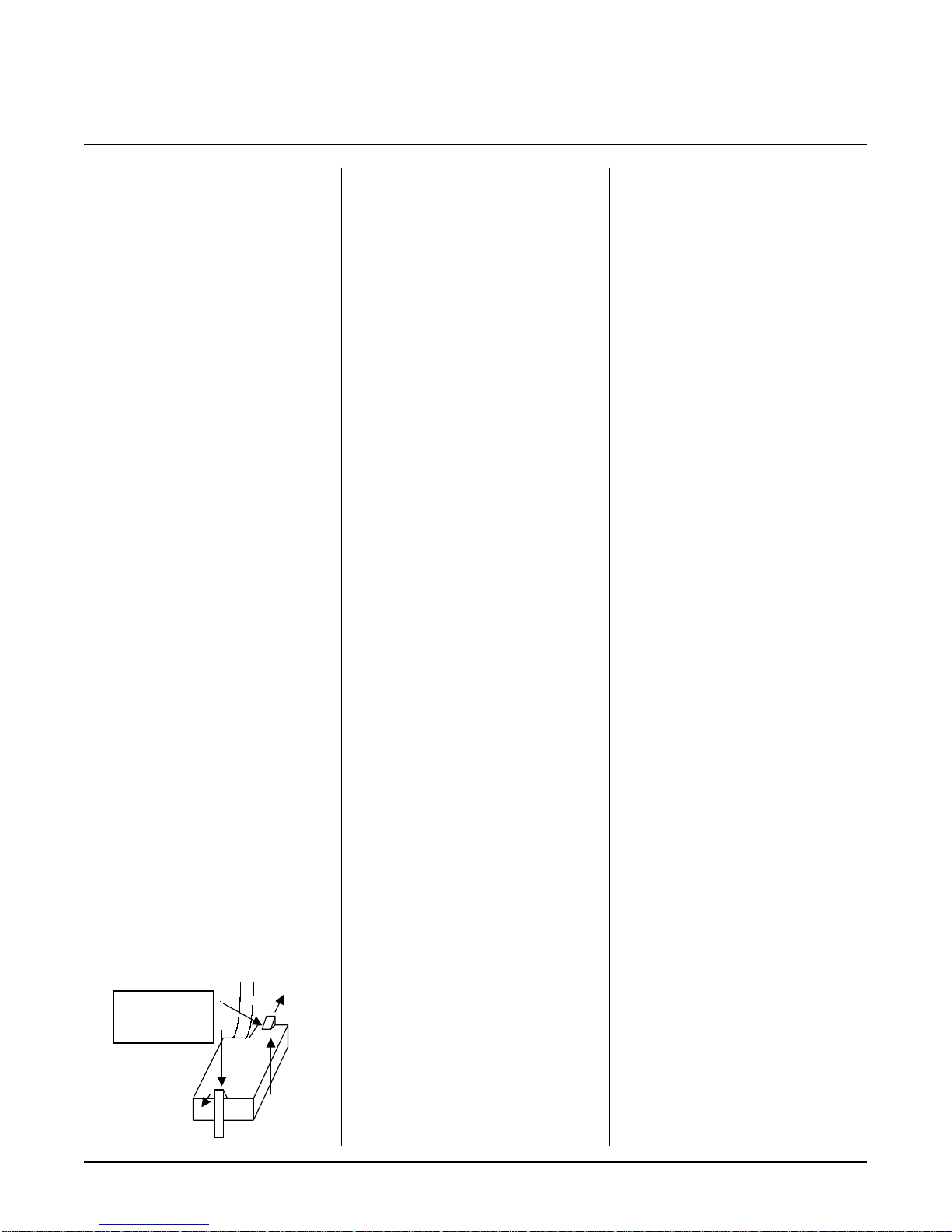
Step 10:
With short Phillips
screwdriverremovefourscrews
holdingassembly to top ofstove
Push both clips
away from
switch to release
Step 11:
Replacewithnew
assembly
Step 12:
LatchReplacement (latch
warpedorbent): Removetwo
Phillips screws holding latch in
place and replace with new latch.
Note:
Donot over tighten screws
as they must allow movement of
the latch back and forth.
Self Clean Operation:
During selfclean,door automati-
cally locks (wax motor energized
and pushes latch to lock) and
coolingfan starts. temperatures
cycle off the timer.
When door locks, “black”
microswitch closes, sends signal to
timer to confirm door locked - unit
will begin self clean cycle.
If latch is stuck and door does not
lock, self clean program will shut
down.
If any of the 2 microswitches on the
selfclean assembly malfunction,
unit will not self clean properly.

Section 5
MLSM2003-09-03
14
Procedure F
- Timer Relay Board
Step 1:
Disconnect power supply to
range.Pullrangeawayfromwall
andremovebackguardheldby3
screws and washers. See Proce-
dure A Step 1.
Step 2:
PropTop Up.See Proce-
dure P.
Step 3:
Remove one wire at a time
fromfaultyrelayboarduntonew
board.
Step 4:
Removefournutsholding
relay board to access panel -
ensure that non conductive spacers
are also transferred to new board.

Section 5
15 MLSM2003-09-03
Procedure G
- Timer Coaxial Cable
Step 1:
Disconnect power supply to
range.Pullrangeawayfromwall
andremovebackguardheldby3
screwsand washers. See Proce-
dure A Step 1.
Step 2:
PropTop Up.See Proce-
dure P.
Step 3:
Inspectcable for visible
damageandreplaceasneeded. If
timer does not operate properly,
one of probable components is the
coaxial cable (other probable
components are the timer and the
relayboard)
Step 4:
Pull locking tabs away and
releasecablefromrelayboard.
Step 5:
Release coaxial cable from
timer(see Procedure B for timer
access).
Step 6:
Replace cable - please
cable is routed exactly as it was
and that it does not interfere with
anyotherwiring.

Section 5
MLSM2003-09-03
16
Procedure H
- Cooling Fan & Limit
Step 1:
Disconnect power supply to
range.Pullrangeawayfromwall
andremovebackguardheldby3
screwsand washers. See Proce-
dure A Step 1.
Step 2:
Removerange’sbackpanel
(Seeprocedurexxx)
Step 3:
Test continuity across
cooling fan’s terminals (pull black
and red wires). If fan test in good
condition, test wiring.
Step 4:
To test wiring, place
multimeterprobeoneachwireand
testforcontinuity between fan and
terminal block and to fan limit.
Step 5:
To access fan limit.
Prop
TopUp.SeeProcedureXXX.
Step 6:
Iffan and wiring in good
condition, test fan limit for continu-
ity. Remove both red wires and test
across, limit should be open and no
readingtakenacross terminals.
Step 7:
If limit test in good condi-
tion, inspect self clean assembly
microswitch(seeProcedureC).
Step 8:
If limit is faulty, replace.
remove wires to limit and transfer
red wires to new temperature limit.
Step 9:
Remove one nut/bolt
holding limit to mounting bracket.
Note:
Please ensure that red wires
do not run parallel with coaxial timer
cable or oven thermostat probe
when finished.

Section 5-3
17 MLSM2003-09-03
Procedure I
- Spark Module
Step 1:
Disconnect power supply to
range.Pullrangeawayfromwall
andremovebackguardheldby3
screwsand washers. See Proce-
dure A Step 1.
Step 2:
PropTop Up.See Proce-
dure P.
Step 3:
Disconnect screw holding
spark module to top and gently drop
down.
Step 4:
Test wiring and connections
to spark module, particularly black,
whiteandgreenwiresto ensure
they are tightly connected.
Step 4:
There should be no conti-
nuity across any of the correspond-
ing terminals from one side of the
module to the other. If any show
continuity, replace spark module.
Step 5:
To replace faulty spark
module,removeonewire at a time
from old module and transfer to
new module in the exact same
terminals as the original. Please
ensure quick connect leads are
properlyandfully inserted into the
spark module spades (use pliers if
needed).
Step 6:
Spark modules are held in
placebyvelcro.
Step 7:
Test wiringfromspark
moduleto ignition switchesfor
continuity and/or wires to elec-
trodes. Replaceas needed.
IMPORTANT: ALL GASWORKTO
BEPERFORMEDBYA QUALIFIED
GASTECHNICIAN.

Section 5-3
18 MLSM2003-09-03
Procedure J
- Regulator Replacement
Step 1:
Disconnect power supply to
range and shut off gas supply.Pull
rangeawayfromwallandremove
backguard held by 3 screws and
washers. See Procedure A Step 1.
Step 2:
PropTop Up.See Proce-
dure P.
Step 3:
Beforereplacingregulator
becauseflames are toohighor too
low,checkregulatorcapfor proper
gas setting.
Step 4:
Cap is stamped with either:
”NAT” on the convex side or “LP”on
the hollow concave side. If stove is
set for Nat Gas and it receives
Propane, the flames will be large. If
stove is set to Propane and it
receivesNat Gas, flames will be
small. See Procedure K for Gas
conversionsteps.
Step 5:
If no gas flows through
regulator but there is gas to the
regulator,it is either mounted
backwards (although unlikely,
howeverthereisanarrowstamped
on the body of the regulator to
ensureproperorientation); or it is
faulty.
Step 6:
If installed backwards,
disconnectregulatorfrommanifold
andinletpiping,reverseorientation
and re-install. Check all gas con-
nections with soapy water solution
to ensure no gas leaks.
Step 7:
If regulator is faulty (i.e no
gas flow, leak, etc.) then replace
regulator.
Step 8:
To remove regulator,
carefully rotate and unscrew from
manifold. Ensure new regulator is
oriented with arrow pointing in
directionofgasflowand ensure pipe
dope is used in all threaded connec-
tions.
Step 9:
When finished check all
gas connections with soapy water
solution to ensure no leaks are
present.
IMPORTANT: ALL GAS WORK TO
BE PERFORMED BY A
QUALIFIED GAS TECHNICIAN.

Section 5-3
19 MLSM2003-09-03
Procedure K
- Gas Conversion
Serial number of range must be
provided to ensure correct kit is
ordered. See Table below.
ConversionSteps:
Step 1:
Disconnect power supply to
range and shut off gas supply.Pull
rangeawayfromwallandremove
backguard held by 3 screws and
washers. See Procedure A Step 1.
Step 2:
PropTop Up.See Proce-
dure P.
Step 3:
Remove4screws securing
metal partition to stove top to
access all burners.
Step 4:
Pressureregulatorconver-
sion. Regulatorhasreversiblecap
foreitherNaturalGasorPropane.
SeeProcedureJ for details on
regulatoraccess.
Step 5:
To reverse regulator cap,
removewithlargeflatbladescrew-
driverturning CCW. The gas being
convertedto must be stamped on
the outside of the cap. Position cap
backonregulator, press andturn
CW to lock in place
Step 6:
Burnervalvessimmer jet
conversion. Removecontrolpanel:
pry open the metal plugs using a
smallbladescrewdriver(ensure
powerisoffunit).
Step 7:
using 3/8” deep socket
wrench,loosennutholdingcontrol
panel to stove top and gently pull
forwardtoexposevalves.
Step 8:
Use small flat blade screw-
drivertoremoveoriginalsimmerjets
andreplacewithappropriately
numberedsimmerjets (all jets have
theirnumberstamped on the head -
refertoconversionkitchart for
details). Donotovertighten. There
aretwosimmerjetsper valve,
exceptforgrillburnerswhichhave
onlyonepervalve.
Step 9:
Surfaceburnerorifice
conversion-outerflamering.
Removeexistingorificesandreplace
with new ones as indicated in
conversion kit chart. Use two
wrenchestopreventtwistingofgas
tubing.
Step 10:
Surfaceburnerorifice
conversion-innerflamering.Re-
movebrassnut(using two
wrenches)andremoveold“cap”.
Replaceandtighten.

Section 5-3
20 MLSM2003-09-03
Procedure K
- Gas Conversion
Step 12:
Air shutter adjustment will
be needed for small simmer setting.
Approximateairholecoverageis1/2
coveredforNatGas.
Step 13:
Grill models only. There
isonly valve simmer jet andone
burnerjet.
Air shutter will need adjusting: LP
fullyopen, Nat Gas open0.40”.
North American Natural Gas
Description Size Part no./Model
3520/3525 3620/3625 3620/3625BBQ
#38109 #38110 #38111
main jet simmer 34 #3669 4 6 4
main jet 1.7 #3860 4 6 4
valveouter 0.4 #7640OR#3856 4 6 4
valveinner 0.88 #3857 4 6 4
grillJet 1.18* #3516 0 0 2
grillvalve 0.58 7636 0 0 2
venturi #3667 4 6 4
North American Liquid Propane
Description Size Part no./Model
3520/3525 3620/3625 3620/3625BBQ
#38112 #38113 #38114
main jet simmer 7 #3670 4 6 4
main jet 1.1 #3861 4 6 4
valveouter 0.25 #3858 4 6 4
valveinner 0.54 #3859 4 6 4
grillJet 0.85* #3517 0 0 2
grillvalve 0.4 #7640OR#3856 0 0 2
venturi #3667 4 6 4
* These orifices use standard size orifice #3519 0.74 drilled out to following size:
#35170.85for North American Liquid Propane (L/P) kits
Conversion/Orifice Charts
Step 11:
Air shutter adjustment will
be needed for small simmer setting.
Approximateairholecoverageis1/4
coveredforLP
IMPORTANT: ALL GASWORKTO
BEPERFORMEDBYA QUALIFIED
GASTECHNICIAN.
Air Shutter Adjustments may be
needed to adjust flame patterns
in the field after conversion or
new appliance installation.
Other manuals for Legacy 3530
1
This manual suits for next models
5
Table of contents
Other Heartland Appliances Range manuals

Heartland Appliances
Heartland Appliances 7100 User manual

Heartland Appliances
Heartland Appliances 5200 User manual

Heartland Appliances
Heartland Appliances 9100 User manual

Heartland Appliances
Heartland Appliances Legacy 3630 User manual

Heartland Appliances
Heartland Appliances U109760-02 User manual

Heartland Appliances
Heartland Appliances 3825 User manual

Heartland Appliances
Heartland Appliances Metro User manual

Heartland Appliances
Heartland Appliances 4200 User manual


