manuals.online logo
Brands
  1. Home
  2. •
  3. Brands
  4. •
  5. Heartland
  6. •
  7. Garden House
  8. •
  9. Heartland VALUE Series User manual

Heartland VALUE Series User manual

16011-NG
Call Us First!
DO NOT RETURN TO STORE.
For questions on assembly or for general inquiries, you may contact us in the following ways:
Call customer service: 1-800-577-9663
Did you enjoy building your shed?
JOIN OUR TEAM
AND MAKE UP TO $1,500/WEEK*
o
r
v
i
s
i
t
b
a
c
k
y
a
r
d
i
n
s
t
a
l
l
e
r
.
c
o
m
Flexible schedule No selling,
just building Bonus incentives
available
S
c
a
n
t
h
e

o
w
c
o
d
e
t
o
a
p
p
l
y
t
o
d
a
y
.
INSTALLERS
WANTED
*based on number of completed installations
Call a Recruiter Today! 734-365-7000
visit us online at
help.backyardproducts.com
AVOID THE WAIT!
Submit a help request
Answers to frequently asked questions
Live chat with an agent
Review your product for the chance to win a $500 Visa Gift Card.
A new winner is selected every 2 months.
Win $500
Write a Backyard Products, LLC. product review at backyardreviews.net for a chance to win a $500 Visa gift card. No purchase necessary to enter. Must be
legal U.S. resident (including DC & Puerto Rico), 18 or older to participate. Taxes on prize are responsibility of winner. Odds of winning depend on the number
of eligible reviews received. Void where prohibited. For complete details and ocial rules, visit https://backyardreviews.net/sweepstakes-rules.
Scan
QR code above.
Click
‘write a review’
Find your product.
Tell us what you think.
Submit your review.
You’ll be notified by e-mail if
you’ve won the $500 gift card.
How to Enter: Open camera.
Aim. Tap.
o
r
v
i
s
i
t
b
a
c
k
y
a
r
d
r
e
v
i
e
w
s
.
n
e
t
A Backyard Products Company
KEEP THIS MANUAL FOR FUTURE REFERENCE
ACTUAL FLOOR SIZE IS 141 x 96" (358 x 244 cm)
STRATFORD 12' x 8' (366 x 244 cm)
ASSEMBLY MANUAL
VALUE SERIES
16011-NG 06/08/2021
BEFORE YOU BEGIN
IMPORTANT!
READ INSTRUCTIONS THOROUGHLY PRIOR TO BEGINNING ASSEMBLY.
• BUILDING RESTRICTIONS AND APPROVALS
Be sure to check local building department and homeowners association for specic restrictions and/ or requirements before building.
• ENGINEERED DRAWINGS
Contact our Customer Service Team if engineered drawings are needed to pull local permits.
• SURFACE PREPARATION
To ensure proper assembly you must build your shed on a level surface.
Recommended methods and materials to level your shed are listed on page 8.
• CHECK ALL PARTS
Inventory all parts listed on pages 4-6.
• ADDITIONAL MATERIALS
You will need additional materials to complete your shed. See pages 3 for required and optional materials and quantities.
***CONTACT OUR CUSTOMER SERVICE TEAM
IF ANY PARTS ARE MISSING OR DAMAGED***
- Order form and warranty at back of manual -
Call: 1-800-577-9663 email: customerservice@heartlandind.com
2
TOOLS
Safety! Always use approved safety glasses during assembly.
OptionalRequired
HELPFUL REMINDER SYMBOLS
Look for these symbols for helpful reminders throughout this manual.
ORIENT LUMBER AND TRIM FOR BEST APPEARANCE
= Assistance Required; (2) or more people.
= Ensure squareness.
= Important required step or operation.
= Helpful assembly hint.
= Mark part with pencil.
= Beginning of steps for assembly or installation.
= You have nished the assembly or installation.
= Level
qGloves
Framing lumber is graded for structural strength and not appearance. Exterior trim is graded for one good side.
Always install the material leaving the best edge and best surface visible. Please remember that these blemishes in no way
negatively affect the strength or integrity of our product. (See Fig. A, B, C.)
A
qSafety Glasses
qTape Measure
qPaint Tools
qLadder
qCaulk Gun
qHammer
qLevel
FINISH
BEGIN
qPencil
qPhillips
Screwdriver
qTool Belt/
Nail Pouch
qChalk Line
qNail Gun
• gun nails
qTin Snips
(for drip edge)
qSquare or
qUtility Knife
qShingle Blades
B C
qHand Saw
qDrill / Driver
q#2 Philips Drive Bit
q3/8" Drill Bit
3
DRIP EDGE ..................... 40 Feet #15 ROOFING FELT
To cover 114 Sq. Ft. of roof area.
REFER TO THE BACK OF THIS MANUAL AND THE MANUFACTURER’S INSTRUCTIONS FOR
INSTALLATION OF SHINGLES, DRIP EDGE AND FELT.
REINFORCED WOOD FLOOR FRAME (OPTIONAL)
IMPORTANT!
Depending on your specic use, you may want to construct a heavy
duty oor frame by adding additional oor joists. Below is a list in
addition to the framing materials above (not included):
x3
x12
2 x 4 x 96" (5 x 10 x 244 cm) Treated Lumber
Cut to (3) 2 x 4 x 93" (5 x 10 x 236,2 cm)
ea. 3" (7,6 cm) Hot Dipped Galvanized Nails Optional 12" (30,5 cm) spacing.
2 x 4 x 96" (5 x 10 x 243,8 cm) Treated Lumber
5/8 x 48 x 96” (1,6 x 122 x 243,8 cm) OSB Panels
(Recommend 5/8” (1,6 cm) (minimum) thick OSB panels)
MATERIAL LIST:
MATERIAL LIST:
CUT LIST:
CUT LIST:
2 x 4 x 93" (5 x 10 x 236,2 cm)
2 x 4 x 144" (5 x 10 x 365,7 cm) Treated Lumber
10D 3” (7,6 cm) Hot Dipped Galvanized Nails
6D 2” (5,0 cm) Hot Dipped Galvanized Nails
2 x 4 x 141" (5 x 10 x 358,1 cm)
5/8 x 45 x 96" (1,6 x 1114 x 243,8 cm)
x10
x3
x10
x2
x40
x186
x2
x1
ADDITIONAL MATERIALS FOR BUILDING YOUR SHED
3-TAB SHINGLES ............................. 5 Bundles
PAINT FOR SIDING .......................... 2 Gallons
Use 100% acrylic latex exterior paint. (2) coats recommended.
CAULK ................................................. 3 Tubes
Use acrylic latex exterior caulk that is paintable.
1" GALVANIZED ROOFING NAILS.... 2 Lbs
For shingles.
PAINT FOR TRIM ............................ 1 Quart
Use 100% acrylic latex exterior paint.
1" GALVANIZED ROOFING NAILS.........1/4 Lb
For roong felt.
CAULK .............................................. 1 Tube
For windows use acrylic latex exterior caulk that is paintable.
TO VALIDATE YOUR WARRANTY YOU MUST USE THE FOLLOWING:
• This shed kit does not include a wood oor frame or oor panels. See pages 10 through 14 for suggested oor construction.
• This shed does not include ANY leveling materials.
• See the FLOOR LEVELING section on page 8 for recommended methods and suggested materials to properly level your
oor, as this will vary depending on your specic site.
• See the CONCRETE FOUNDATION section on page 9 for recommended methods to build your shed on a poured concrete slab.
WOOD FLOOR FRAME (NOT INCLUDED)
FOUNDATION
FLOOR PANELS (NOT INCLUDED)
Use Treated Lumber For
Floor Framing
WOOD SIZE CONVERSION CHART
Nominal Board Size Actual Size
1 x 4.................3/
4" x 3-1/2" (1,9 x 8,9 cm
)
2 x 4..............1-1/2" x 3-1/2" (3,8 x 8,9 cm)
2 x 3..............
1-1/2" x 2-1/2" (3,8 x 6,3 cm
)
1 x 3.................3/
4" x 2-1/2" (3,8 x 6,3 cm
)
PARTS IDENTIFICATION AND SIZES
RS RS
Part identication
letters are stamped on some parts.
Check these locations for
part stamp.
WALLS
PARTS LIST
RAFTERS
TRIM
4
2 x 3 x 24-1/16" (5 x 7,6 x 61 cm)
2 x 3 x 7-7/8" (5 x 7,6 x 20 cm) 1 x 3 x 5" (2,5 x 7,6 x 12,7 cm)
Gauge Block for 3/4" (19 mm)
measurement
2 x 3 x 14-1/2" (5 x 7,6 x 36,8 cm)
2 x 3 x 66-1/2" (5 x 7,6 x 169 cm)
2 x 3 x 29-1/2" (5 x 10 x 75 cm)
2 x 3 x 32-1/2" (5 x 10 x 83 cm)
2 x 3 x 46-1/2" (5 x 7,6 x 118 cm)
2 x 3 x 94-1/2" (5 x 7,6 x 240 cm)
2 x 3 x 96" (5 x 7,6 x 244 cm)
2 x 3 x 13" (5 x 7,6 x 33 cm)
2 x 3 x 68" (5 x 7,6 x 173 cm)
FL
x2
x1
x1
x5
x1
2 x 3 x 62-1/2" (
5 x 7,6 x
158,8 cm)
x3
x3
x3
x6
x7
x5
x1
FN
DY FZ
KK
KZ
2 x 3 x 22-1/2" (5 x 7,6 x 57 cm)
x2 LV
2 x 3 x 21-1/2" (5 x 7,6 x 55)
x2 LF
NF
PR
PT
RK
OT
5/8 x 3 x 24-3/4" (1,6 x 7,6 x 62,9 cm)
x6 CYZ
5/8 x 3 x 8" (1,6 x 7,6 x 20 cm)
x4 KV
x2 MM 2 x 3 x 76-1/4" (5 x 7,6 x 194 cm)
WNA 5/8 x 4 x 14" (1,6 x 10 x 35,5 cm)
x8
3/8 x 5-3/8 x 5-1/2" (1 x 13,6 x 14 cm) 1 Left / 1 Right
x2
NQ
x2 2 x 3 x 46-7/8" (5 x 7 x 119 cm)
2 x 3 x 65" (5 x 7,6 x 165 cm)
NR
x2
2 x 3 x 70-1/2" (5 x 7,6 x 179 cm)
x2 NO
BJ
2 x 4 x 65-5/8" (5 x 10 x 167 cm) Rafter
AD
x5
3/4 x 2-1/2 x 72-3/8" (1,9 x 6,3 x 184 cm)
x2 KY
x1GAA
x2 KX 5/8 x 3 x 21-3/4" (1,6 x 7,6 x 55 cm)
8 x 24" (20 x 61 cm) Gusset
x10
2 x 4 x 46-13/16" (5 x 10 x 119 cm) Rafter
NU
x5
3/4"
(1,9 cm)
5
WALL PANELS / DOOR PARTS LIST
x1
x2 x2
x3 x1x2 x1 x1 x1 x1
7/16 x 18 x 96”
(1,1 x 46 x 244 cm)
x1
7/16 x 18 x 48”
(1,1 x 46 x 122 cm)
7/16 x 48 x 96"
(1,1 x 122 x 244 cm)
7/16 x 47-7/8 x 48"
(1,1 x 122 x 122 cm)
x1 x1
3/8 x 7-7/8 x 94-1/2"
(0,9 x 20 x 240 cm)
3/8 x 48 x 72"
(1 x 122 x 183 cm)
3/8 x 15-7/8 x 72"
(1 x 40 x 183 cm)
3/8 x 7-7/8 x 46-1/2"
(0,9 x 20 x 118 cm)
Roof Panels are
7/16" (11 mm) thick
Left Door Right Door
x1 x1
1-1/2 x 2-1/2 x 69" (3,8 x 6,3 x 175,3 cm)
x2
OO
5/8 x 3-7/8 x 96" (1,6 x 9,8 x 244 cm)
x1
ROOF PANELS
NOTES
OO
x1
69" Door Stiffener (175,3 cm)
6
NOTE:
If you are using a nail gun, nails may
be used where screws are shown for
quicker assembly.
Length of nail must match screw length.
7/16 x 20 x 96"
(1,1 x 51 x 244 cm) 7/16 x 11-3/4 x 96"
(1,1 x 30 x 244 cm)
1 x 3 x 96"
(2,5 x 7,6 x 244 cm)
Window
23-7/8 x 96"
(61 x 244 cm) Peg Board
x1 x2
x1
x1
x1
x30
x74
x36
x2 Boxes
x4 Boxes
x112
x112
x25
x75
3" (7,6 cm)
3" (7,6 cm)
2" (5,0 cm)
2" (5,0 cm)
2" (5,0 cm)
1-1/4" (3,2 cm)
1-1/2" (3,8 cm)
1" (2,5 cm)
3/4" (19 mm)
SHELF & WINDOW PARTS LIST
FASTENERS / HARDWARE BAG (Shown actual size)
NAIL BOXES (Shown actual size)
DOOR HARDWARE (Not actual size)
BE
3/4" (19 mm) 3/4" (19 mm) 3/4" (19 mm)
64" Metal Threshold
Bagged separately / special coating
x2
x8
x1 x1
x7 x11
7
BUILDING ANATOMY
1. Sub-assembled doors with attached hinges.
2. 2x3 wall studs have been engineered to support roof load and to meet demanding wind loads.
3. Sidewall top and bottom plates tie wall studs together and provide nailing support for top and bottom edge of siding.

Oversized wood gussets at peak provide a strong connection for rafter halves.

6. Collar tie and over-door header maintains door frame integrity.
7. Corner studs & end rafters are positioned to the outside of the siding where they serve the dual purpose of framing and trim.
8. The EZ Frame design transfers the roof load to the front and back walls allowing for reduced framing at the side walls.

This building has been designed using our patented EZ Frame construction method.
EZ Frame is a unique construction method which has been engineered to use fewer
framing members. This reduces assembly time and cost by as much as 30% compared to
conventional construction methods. EZ Frame patent no. 5,666,766
All of our buildings have been engineered to withstand demanding wind and snow loads.
If you live in an area with extreme wind/snow load requirement, contact
us and we can assist with engineering to meet your local codes.
1
2
3
4
5
6
7
8
9
9
7
3
2
6
8
5
4
1
8
FLOOR LEVELING OPTIONS
There are multiple ways to level your oor frame. Our recommended leveling method is shown below.
Leveling materials are not included in this kit.
PREFERRED METHOD - 4x4 TREATED RUNNERS (NOT INCLUDED)
• Level under 4x4 runners only.
• Locate leveling material 12" from ends of runners and no more than 48" apart.
• Asphalt shingles should be used between 4x4 runners and blocks or treated lumber. Never use
shingles in direct contact with ground.
• For best results and aiding in water drainage use gravel under each concrete block.
LEVELING METHODS
• If you are building your shed on a concrete foundation see the following page.
CONCRETE
MATERIAL REQUIRED
x2
Fasteners for Frame to 4 x 4.
(3" Screws shown as one option.) Minimum (28) 3" screws / exterior grade.
Use only wood treated for ground contact and fasteners approved for use with treated wood.
Always support frame seams.
Leveling higher than 16" not recommended.
LEVELING MATERIALS
Gravel
2x4 Treated Lumber
Solid Masonry Blocks in 1", 2", 4" or 8" thickness
Asphalt Shingles
8" Block
4" Block
Gravel
Gravel
Do not exceed 16".
4x4 Runner
Shingle
Shingle
Maximum between leveling
material locations.
48"
12"
2x4 Treated Lumber
2" Block
Level
12"
12"
(30,5 cm)
12"
(30,5 cm)
• 3" Screws angled into 4x4.
• (2) at each point frame
•and 4x4 touch.
4 x 4 x 12' (10 x 10 x 365,7 cm) Treated Lumber
9
A
BC
4"
(10 cm)
3-1/2"
(8,9 cm)
DOOR
2 x 4 x 12' (5 x 10 x 366 cm)
2 x 4 x 8' (5 x 10 x 244 cm)
Caulk
Requires:
x2
x2
x2
MUST be treated lumber.
96" (244 cm)141" x 96" (358 x 244 cm) 89" (226 cm)12'x 8' (366 x 244 cm) 141" (358 cm)
AActual Size B CBuilding Size
CONCRETE FOUNDATION
If you choose to install your kit on a concrete slab refer to the diagram below.
• A treated 2 x 4" (5 x 10 cm) sill plate is required when installing your shed on concrete. Hint: Purchase full length treated lumber.
• Use a high quality exterior grade caulk beneath all sill plates.
• Fasten 2 x 4" (5 x 10 cm) sill plates to slab using approved concrete anchors (fasteners not included).
• Check local code for concrete foundation requirements.
NOTES
Treated Sill Plate
Caulk between sill plate
and concrete.
Allow new concrete slabs to cure for at least seven (7) days.
10
93"
(236 cm)
96"
(244 cm)
141”
(358 cm)
96”
(243,8 cm) 80”
(203,2 cm)
112”
(248,4 cm)
64”
(162,6 cm) 48”
(122 cm)
32”
(122 cm) 16”
(40,6 cm)
128”
(325,1 cm)
13”
(33 cm)
1-1/2”
(3,8 cm)
x40 3" (7,6 cm)
x10
x2
2 x 4 x 93" (5 x 10 x 236 cm)
2 x 4 x 141" (5 x 10 x 358 cm)
PARTS REQUIRED:
FINISH
You have nished your oor frame.
Secure with (2) 3" nails at each mark.
Arrange parts on a at surface. Measure and mark.
Center
on marks
FLOOR FRAME (NOT INCLUDED)FLOOR FRAME (NOT INCLUDED)
Flush
Flush
Use Treated lumber
HINT:
For easier nailing
stand on frame.
3" (7,6 cm)
Nails
DOOR
11
First, secure
at ends with
one fastener.
Second,
secure
at ends with
one fastener.
170-9/16"
(433,3 cm)
170-9/16"
(433,3 cm)
Fig. A
FINISH
LEVEL AND SQUARE FLOOR FRAME
Before attaching oor decking, it is important to level and square the oor frame.
A level and square oor frame is required to correctly construct your shed.
2
3
4
Use level and check the frame is level before applying oor panels.
Check for frame squareness by measuring diagonally across corners. If the measurements are the
same, the frame is square. The diagonal measurement will be approximately 170-9/16" (433,3 cm).
When the frame is level and square secure one side of frame to the 4x4 runners using one fastener at
ends of each runner. Move to the opposite end of the frame. Secure the frame to 4x4 runners with one
fastener at ends of each runner making sure the frame remains square (Fig. A).
Once the oor frame is level and square fasten the frame to the x4 runners at each point
where the frame contacts the 4x4 runners.
See page 8 for the preferred oor leveling method.
12
Move to the opposite side. Using the long edge of the panel as a lever, move the
panel side-to-side until the top corner is ush to the oor frame (Fig. B).
Secure panel with (2) 2" nails in the corners.
2
BEGIN
1
3
4Continue securing the panel with 2" nails 6" spaced apart on edges and 12" apart inside panel.
Use a chalk line or use pre-painted grid lines to nail into joists under panel.

and squaring frame.
Check the oor frame is square by measuring diagonally across the frame corners. If the measurements are the
same your oor frame is square. The measurement will be approximately 170-9/16" (433,3 cm) (Fig. C).
PARTS REQUIRED:
x1 5/8 x 45 x 96"
(1,6 x 114 x 243,8 cm)
x62 2" (5,1 cm)
FLOOR PANELS (NOT INCLUDED)
Attach the 5/8 x 45 x 96" panel with the rough side up (painted-grid lines side) with the 45"
edge and corner ush to the oor frame (Fig A).
Secure panel with (2) 2" nails in the corners.
Floor panels not included. See
page 3 for panel sizes
and quantities.
48"
(122 cm)
141"
(358 cm) 96"
(243,8 cm)
Flush
(2) Nails
170-9/16"
(433,3 cm)
170-9/16"
(433,3 cm)
Fig. A
Fig. B
Fig. C
3/4"
(1,9 cm)
13"
(33 cm)
3/4"
(1,9 cm)
6"
(15 cm)
12" (30 cm)
3/4"
(1,9 cm)
Flush
(2) Nails
45"
(114 cm)
141"
(358 cm)
6"
(15 cm)
Grid lines up
12"
(30 cm)
Flush
Flush
Flush
(2) Nails
(2) Nails
3/4"
(1,9 cm)
Fig. A
Fig. B
96”
(243,8 cm)
DOOR
13
PARTS REQUIRED:
x2 5/8 x 48 x 96"
(1,6 x 121,9 x 243,8 cm)
x124 2" (5,1 cm)
FLOOR PANELS (NOT INCLUDED)
48"
(122 cm)48"
(122 cm)
96"
(243,8 cm)
141"
(358 cm)
6"
(15 cm)
12"
(30) cm
Flush
FlushFlush
DOOR
FINISH
Your oor panels are now installed.
Continue installing panels with rough side up (painted grid lines).
Use grid lines on panel for 2" nails 6" spaced apart on edges and 12" apart inside panels.
5
14

Re-level if needed.
HINT:
IMPORTANT!

• Organize your assembly procedure during the build process
to avoid over-handling of the walls.
GABLE WALL
LEFT
FRONT WALL
GABLE WALL
RIGHT
BACK WALL
15
LEFT WALL
PARTS REQUIRED:
x1 2 x 3 x 76-1/4" (5 x 7,6 x 194 cm)
x1
MM
Flush
Primed
side down
Fig. B
Fig. A
6"
(15 cm)
2-1/2"
(6,4 cm)
76-1/4"
(194 cm)
76-1/4"
(194 cm)
Check for correct
panel shape.
Edges of panel should be ush to MM.
Secure panel to MM with 1-1/4" screws spaced 6" apart.
Arrange parts on the at side on oor, as shown (Fig. A,B).
Panel should be primed side down (Fig. B).
x13 1-1/4" (3,2 cm)
MM
16
LEFT WALL
x1
Check for correct
panel shape.
PARTS REQUIRED:
x1
3
Edges of panel should be ush to NO.
Secure panel to NO with 1-1/4" screws spaced 6" apart.
Arrange parts on the at side on oor, as shown (Fig. A, B).
Panel should be primed side down (Fig. B).
Flush
6"
(15 cm)
NO
70-1/2"
(179 cm)
2 x 3 x 70-1/2" (5 x 7,6 x 179 cm)
NO
FINISH
You have nished building your (2) left wall assemblies.
Primed
side down Fig. B
x12 1-1/4" (3,2 cm)
2-1/2"
(6,4 cm)
Fig. A
70-1/2"
(179 cm)
17
LEFT WALL
1"
(2,5 cm) 2-1/2"
(5,4 cm)
33-1/2"
(85 cm)
1-1/4"
(3,2 cm)
33-1/2"
(85 cm)
2-1/2" (6,4 cm)
Flush
Flush 12"
(30 cm)
6"
(15 cm)
PT
PT
temporary support
RK
temporary support
x12 1-1/2" (3,8 cm)
PARTS REQUIRED:
2
3
Install KZ rst, measuring 1" (2,5 cm) from panel bottom.
Secure KZ with 1-1/2" (only) nails 6" apart.
Place PT ush to KZ and edge of panel. Hold the 33-1/2" (85 cm) measurement.
Secure with 1-1/2" nails spaced 12" apart.
Arrange KZ and PT on at on oor, as shown.
Place panel on KZ and PT with primed side up.
Primed side
up
Use only 1-1/2"
(3,8 cm) long nails
x1
x1
x2
LEFT WALL
REAR ASSEMBLY
KZ
2 x 3 x 32-1/2" (5 x 10 x 83 cm) 2 x 3 x 96" (5 x 7,6 x 244 cm)
KZ
PT
2 x 3 x 13" (5 x 7,6 x 33 cm)
x1 RK
18
58-1/4"
(148 cm)
5/8"
(16 mm) 2-1/2"
(6,4 cm)
Use
as spacer
Use Gauge Block
as spacer 3/4"
(19 mm)
Flush
58-1/4"
(148 cm)
21-1/2"
(54,6 cm)
29-1/2"
(75 cm)
Flush
1-1/4"
(3,2 cm)
2-1/2"
(6,4 cm)
1-1/4"
(3,2 cm)
12"
(30 cm)
6"
(15 cm)
LEFT WALL
BJ
Flush
LF
PT
RK temporary support
x17 1-1/2" (3,8 cm)
PARTS REQUIRED:
6
4
5
7
8
Secure LF with 1-1/2" (only) nails spaced 6" apart.
Place PT ush to LF and panel edge. Hold the 58-1/4" (148 cm) measurement.
Secure with 1-1/2" nails spaced 12" apart.
Place the 5/8" spacer on PT.
Place BJ ush to spacer and nail.
Place 3/4" gauge block on PT.
Place LF ush on gauge block and nail.
Use only 1-1/2"
(3,8 cm) nails.
x1 2 x 3 x 96" (5 x 7,6 x 244 cm)
PT
2 x 3 x 29-1/2" (5 x 10 x 75 cm)
BJ
x1
2 x 3 x 21-1/2" (5 x 7,6 x 55)
x1 LF
5/8 x 3 x 14" (1,6 x 7,6 x 35,5 cm) 3/4" GAUGE
BLOCK
TEMPORARY SPACER
x1

Other manuals for VALUE Series

9

This manual suits for next models

1

Other Heartland Garden House manuals

Heartland VALUE Series User manual

Heartland

Heartland VALUE Series User manual

Heartland GENTRY GABLE VALUE Series User manual

Heartland

Heartland GENTRY GABLE VALUE Series User manual

Heartland VALUE Series User manual

Heartland

Heartland VALUE Series User manual

Heartland ADD ONE 12 x 4 User manual

Heartland

Heartland ADD ONE 12 x 4 User manual

Heartland VALUE Series User manual

Heartland

Heartland VALUE Series User manual

Popular Garden House manuals by other brands
forest-style HEIDI Building instructions

forest-style

forest-style HEIDI Building instructions

Mercia Garden Products 03HEL1010DDFW-V2 General instructions

Mercia Garden Products

Mercia Garden Products 03HEL1010DDFW-V2 General instructions

Grosfillex DECO11 Assembly instructions

Grosfillex

Grosfillex DECO11 Assembly instructions

VISSCHER BARCELONA instructions

VISSCHER

VISSCHER BARCELONA instructions

Mercia Garden Products 01DTPRMSHPN1008DDOP-V2 General instructions

Mercia Garden Products

Mercia Garden Products 01DTPRMSHPN1008DDOP-V2 General instructions

Palmako Helena 18.6m2 Assembly instructions

Palmako

Palmako Helena 18.6m2 Assembly instructions

Madeira LILAC Assembly instruction

Madeira

Madeira LILAC Assembly instruction

Holz-Blech AIDA 40 manual

Holz-Blech

Holz-Blech AIDA 40 manual

Storite rite 5 Assembly instructions

Storite

Storite rite 5 Assembly instructions

Big Lots L-GZ136PST-8 instruction manual

Big Lots

Big Lots L-GZ136PST-8 instruction manual

telluria ELEGANTO 2724 OLKL Assembly instructions

telluria

telluria ELEGANTO 2724 OLKL Assembly instructions

STILLA Glendale Assembly instructions

STILLA

STILLA Glendale Assembly instructions

Mercia Garden Products 06LOG002-V1 General instructions

Mercia Garden Products

Mercia Garden Products 06LOG002-V1 General instructions

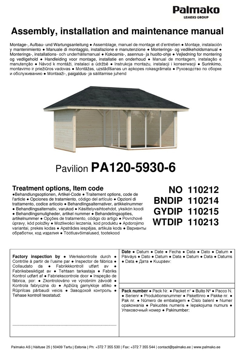
Lemeks Palmako PA120-3030-5 Assembly, installation and maintenance manual
Lemeks

Lemeks Palmako PA120-3030-5 Assembly, installation and maintenance manual
Dancover Greenhouse GH117010 manual

Dancover

Dancover Greenhouse GH117010 manual

STILLA S3071 Assembly instructions

STILLA

STILLA S3071 Assembly instructions

Duratuf Whitford Assembly instructions

Duratuf

Duratuf Whitford Assembly instructions

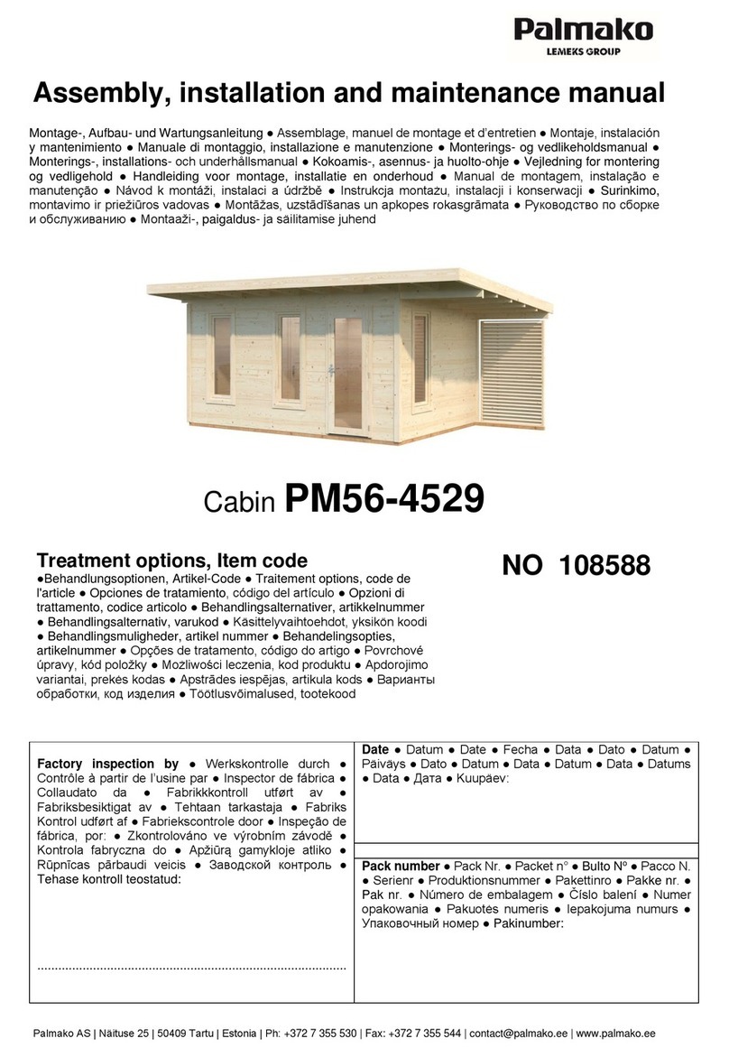
Lemeks Palmako PM70-5957 Assembly, installation and maintenance manual

Lemeks

Lemeks Palmako PM70-5957 Assembly, installation and maintenance manual

manuals.online logo
manuals.online logoBrands
  • About & Mission
  • Contact us
  • Privacy Policy
  • Terms and Conditions

Copyright 2025 Manuals.Online. All Rights Reserved.