Heat & Glo TIARA I-B User manual

August 1, 2008
TIARA I-B
TIARA II-B
DIRECT VENT ROOM HEATER
O-T
O-T L
Tested and
Listed by
Portland
Oregon USA
OMNI-Test Laboratories, Inc.
CUS
TIARAI-BK-B
TIARAI-BR-B
TIARAI-CTO
TIARAI-CES
Models:
TIARAII-BK-B
TIARAII-BR-B
TIARAII-CTO
TIARAII-CES
Owner’s Manual
Installation and Operation
DO NOT DISCARD THIS MANUAL
CAUTION
• Important operating and
maintenance instructions
included.
• Leave this manual with
party responsible for use
and operation.
• Read, understand and
follow these instructions
for safe installation and
operation.
• Do not store or use gasoline or other flam-
mablevaporsandliquidsinthevicinityofthis
or any other appliance.
• What to do if you smell gas
- Do not try to light any appliance.
Do not touch any electrical switch. Do not
use any phone in your building.
- Immediately call your gas supplier from a
neighbor’sphone.Followthegas supplier’s
instructions.
- If you cannot reach your gas supplier, call
the fire department.
• Installation and service must be performed
by a qualified installer, service agency, or the
gas supplier.
WARNING: If the information in these
instructions is not followed exactly, a fire
or explosion may result causing property
damage, personal injury, or death.
Installation and service of this appliance should be
performed by qualified personnel. Hearth & Home
TechnologiessuggestsNFI certified orfactory-trained
professionals, or technicians supervised by an NFI
certified professional.
7010-149M
HOT SURFACES!
Glass and other surfaces are
hot during operation AND
cool down.
WARNING
Hot glass will cause burns.
• Do not touch glass until it is cooled
• NEVER allow children to touch glass
• Keep children away
• CAREFULLY SUPERVISE children in the same room
as appliance
• Alert children and adults to hazards of high
temperatures
High temperatures may ignite clothing or other
flammable materials.
• Keep clothing, furniture, draperies and other
combustibles away.
DO NOT
DISCARD
This appliance may be installed as an OEM installation in manufactured
home (USA only) or mobile home and must be installed in accordance with
themanufacturer'sinstructionsandthemanufacturedhomeconstructionand
safetystandard,Title24CFR,Part3280orStandardforInstallationinMobile
Homes, CAN/CSAZ240MH.
This appliance is only for use with the type(s) of gas indicated on the rating plate.
In the Commonwealth of Massachusetts:
• installationmust be performedby a licensedplumber or gas
fitter.
See Table of Contents for additional Commonwealth of Mas-
sachusetts requirements.

Page 2 Heat & Glo · Tiara I B & Tiara II B · 7010-149M August 1, 2008
Read this manual before installing or operating this appliance.
Please retain this owner's manual for future reference.
Congratulations
Congratulations on selecting a Heat & Glo gas appliance -
anelegantandcleanalternative towoodburningappliances.
TheHeat&Glogasapplianceyou have selected is designed
to provide the utmost in safety, reliability, and efficiency.
As the owner of a new appliance, you'll want to read and
carefully follow all of the instructions contained in this
Owner's Manual. Pay special attention to all Cautions and
Warnings.
ThisOwner'sManualshouldberetainedforfuturereference.
We suggest that you keep it with your other important
documents and product manuals.
The information contained in this Owner's Manual, unless
noted otherwise, applies to all models and gas control
systems.
Your new Heat & Glo gas appliance will give you years of
durable use and trouble-free enjoyment. Welcome to the
Heat & Glo family of gas appliance products!
SAMPLE OF RATINGS LABEL
LOCATION: Hang tag attached to rear of appliance
Serial No.
Model Name
Test Lab &
Report No.
Manufactured
Date
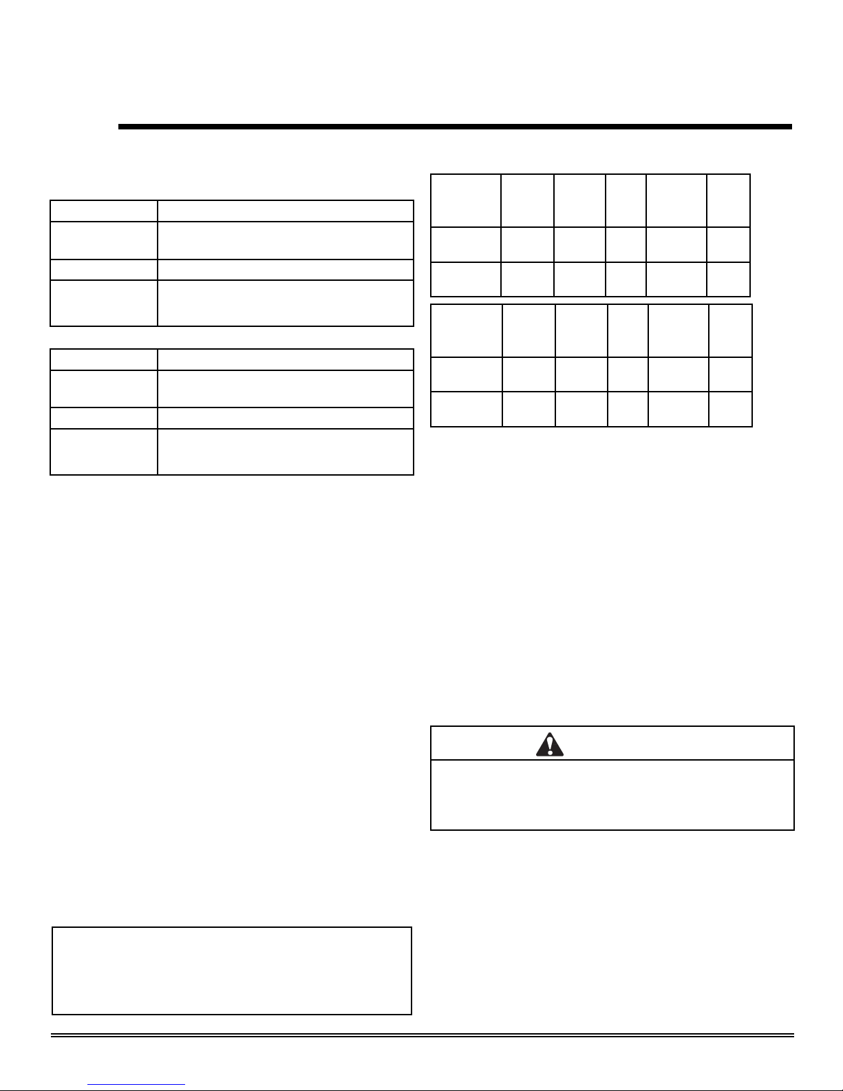
MINIMUM CLEARANCES TO COMBUSTIBLES / ESPACE MINIMUM AUX COMBUSTIBLES
Minimum clearances required from combustible construction for all appliance surfaces. / Espaces minimum exigés de la
construction combustible aux surfaces de l’appareil.
Date of Manufacture / Date du Manufacturier
2008 2009 2010 Feb Mar Apr May Jun Jul Aug Sep Oct Nov DecJan
DO NOT REMOVE THIS LABEL / NE PAS ENLEVER L’ÉTIQUETTE Made in U.S.A. / Fait Aux États-Unis 7010-150
A. Side of stove top to side wall 8-1/2" (216mm) D
u côté du poêle au côté du mur
B. Rear of stove to back wall 1/4" (6mm)
Le contrôle arrière au mur arrière
C. Corner of stove top to side wall 3/8" (9mm) Du coin du dessus du po
êle au mur de côté
D. Minimum Alcove Height 54" (1372mm) Ha
uteur minimum du plancher au plafond
E. Maximum Alcove Depth 36" (914mm) P
rofondeur maximum de l'alcove
F. Minimum Alcove Width 40" (1016mm)
Largeur minimum de l'alcove
G. Stove to Ceiling Clearance 27" (686mm) Le po
êle au dégagement de plafond
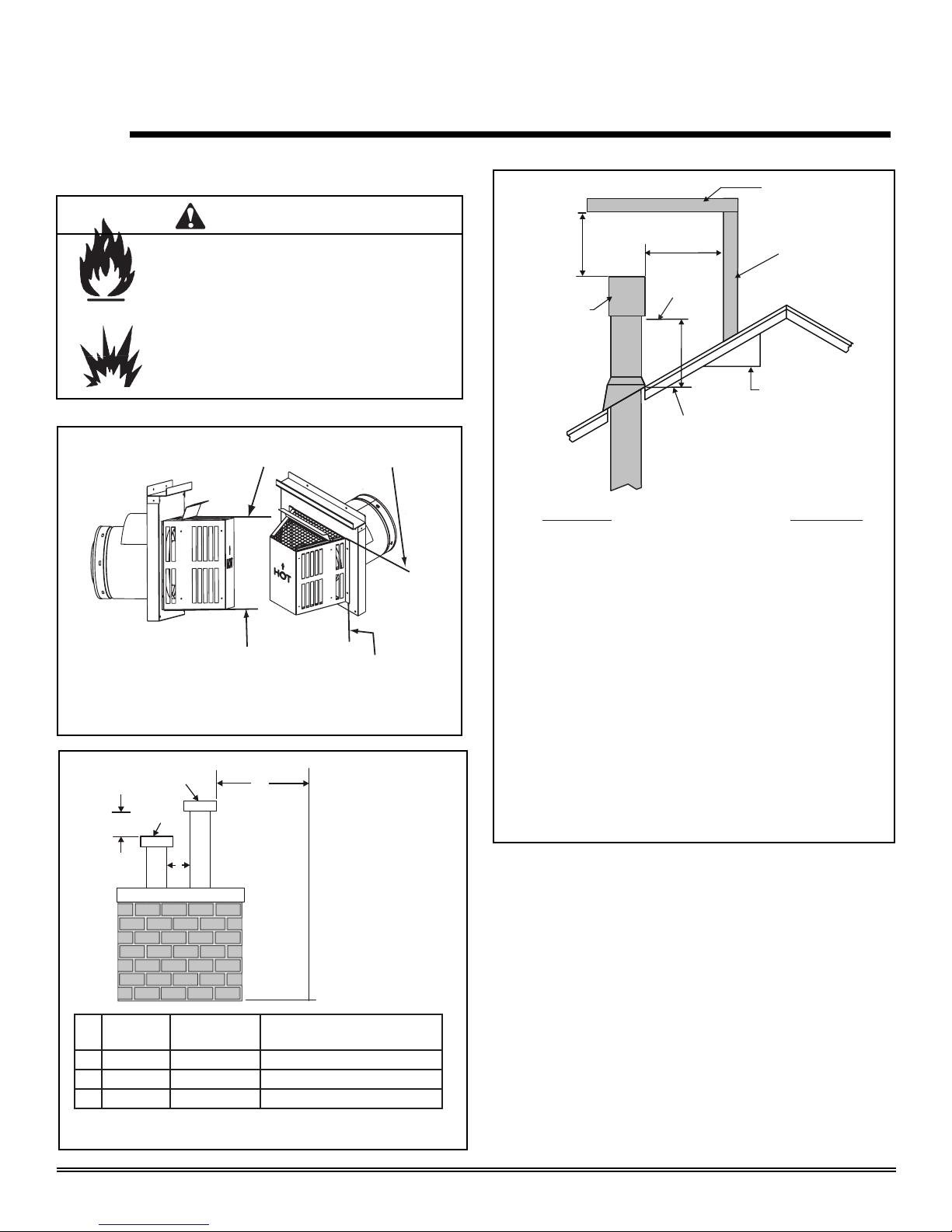
H. Top of Pipe to Combustible 1-1/2" (38mm) Le sommet de tuyau à combustible
Side of Pipe to Combustible 1" (25mm) Le côté de tuyau à combustible
Inside Outside Cornerwall Vent 9" (229mm) À l'intérieur de conduit de mur de coin extérieur
Right and left sides of appliance are determined when facing the front of appliance. / Les
côté gauches et droits de
l'appareil sont d
éterninés lorsque vous
êtes en face de l'appareil.
G-Alcove
A
F
de l'alcôve
90° off top up & out ceiling
clearance 90° du sommet en
haut et hors le degagement de
plafond
A
B
E
A A
G
D
H
"A" measurement is from stove top,
not side /
"A"mesure est du
sommet de poêle, pas le côté
HEARTH: A non-combustible hearth pad is not required. However, the floor beneath the stove must be stable, level, and strong
enough to support the stove without a tipping hazard. / CHEMINÉE: Un coussinet non-combustible de cheminée n’est pas
exigé. Cependant, le plancher en dessous du poêle doit être droit, à niveau et assez fort pour supporter le poêle sans le
hasard de basculer.
C
C
0-2000 FT’ 0-2000FT
Input Rate on “HI” (BTU/Hr) 31,000 30,000 Puissance Évaluée à “HI” (BTU/Hr)
Input Rate on “LO” (BTU/Hr) 22,000 23,000 Puissance Évaluée à “LO” (BTU/Hr)
Maximum Output (BTU/Hr)** 20,943 21,519 Puissance Maximum (BTU/Hr**
Main Burner Orifice .106 .063 Orifice du Brûleur Principal
Minimum Inlet Pressure
(Inches W.C.)
4.5” 11” Pression Minimum de la Valve (pouces W.C.)
Maximum Inlet Pressure
(Inches W.C.)
7.0” 14” Pression Maximum de la Valve (pouces W.C.)
M
anifold Pressure on
“HI”
(Inches W.C.)
3.5” 10” Pression du Collecteur d’ Échappement à “HI” (pouces W.C.)
**Max Venting, Blower On **Ventilation Maximum, Ventilateur Allumé
For use with Propane
Usage Au Gaz Propane
For use with Natural Gas
Usage Au Gaz Naturel
APPROVED FOR CANADA AND USA TO: ANSI Z21.88-2002 / CSA 2.33-02 Vented Gas Fireplace Heaters, and applicable sections of UL307b Gas Burning HeatingAppliances for Manufactured Homes and Recreational
Vehicles, CAN/CGA 2.17-M91 Gas Fired Appliances for use at High Altitudes. This appliance is manufactured for operation with Natural Gas. For conversion to propane Manufacturer's instructions must be used. This
appliance may be installed in a bedroom or bedsitting room; in Canada remote thermostat installation is required.
APPROUVÉ-POUR LE CANADA ET LES ÉTATS-UNIS: ANSI-Z21.88-2002 / CSA 2.33-02 Fournaises au Gaz avec Ventilation, et les sections applicable de UL 307b Appareils de Chauffage Au Gaz our les Maisons Mobiles et les
Vehicules Motoriss, CAN/CGA 2.17-M91 Gas Fired Appliances for use at High Altitudes. Cet appareil est manufactur pour l'operation avec le Gaz Naturel. Pour une conversion au gaz propane les pices du Manufacturier et ses
instructions doivent tre utilises. Cet appareil peut tre utilis dans une chambre à coucher ou salle de sjour, au Canada, l'installation d'un thermostat à distance est exige.
FAN TYPE VENTED CIRCULATOR / VENTILATEUR CIRCULATOIRE
Optional Blower Kit #GFK-160A
/
Le Souifleur Optionel Kit #GFK-160A
120Vac, 60Hz., 12 Amperes or less (ou moins)
Route power cord away from unit. /
Éloignez le fil électrique de l'appareil.
Do not route
power cord under or over stove. /
Ne pas faire passer le fil électrique au dessus ou en dessous de l'appareil.
SAMPLE
SAMPLE
VENTED GAS FIREPLACE HEATER
NOT FOR USE WITH SOLID FUEL
Serial No / Numéro du
Report No. / Rapport Numéro
061-S-43b-5 FOURNAISE AU GAZ AVEC VENTILATION
NE PAS UTILISER AVEC LE COMBUSTIBLE SOLIDE
MODEL / MODÈLE: TIARA I (B)
A division of Hearth & Home Technologies Inc.
20802 Kensington Boulevard, Lakeville, MN 55044
007
O-T
O-T L
Tested and
Listed by
Portland
Oregon USA
OMNI-Test Laboratories, Inc.
CUS
Barcode

Page 3
Heat & Glo · Tiara I B & Tiara II B · 7010-149M
- TABLE OF CONTENTS -
August 1, 2008
Section 1: Listing and Code Approvals
A. Appliance Certifications ......................4
B. Glass Specifications............................4
C. Specifications......................................4
D. High Altitude Installations....................4
E. Non-Combustible Materials.................4
F. Combustible Materials ........................4
G. Requirements for the
Commonwealth of Massachusetts......5
Section 2: Getting Started
A. Design & Installation
Considerations....................................6
B. Tools and Supplies Needed................6
C. Inspect Appliance & Components.......6
Section 3: Appliance Location & Clearances
A. Selecting Appliance Location..............7
B. Clearances to Combustibles -
Tiara I-B..............................................7
C. Clearances to Combustibles -
Tiara II-B.............................................8
Section 4: Termination Locations
A. Vent Termination Minimum
Clearances..........................................9
Section 5: Vent Information
A. Venting Components..........................11
B. Use of Elbows.....................................11
C. Measuring Standards..........................11
D. How to Use the Vent Graph................12
E. Venting Guidelines..............................12
F. Horizontal Termination........................13
G. Vertical Termination............................16
Section 6: Gas Information
A. Fuel Conversions................................24
B. Gas Pressures....................................26
C. Gas Connection..................................26
Section 7: Electrical Information
A. Recommendation for Wire ..................28
B. Connecting to the Appliance...............28
C. Standing Pilot Ignition System
Wiring..................................................28
D. Ignition Module Access and
Battery Replacement ..........................29
Section 8: Appliance Setup
A. Remove Shipping Materials................30
B. Top to Rear Conversion......................30
C. Damper Adjustment............................31
D. Shutter Adjustment .............................32
E. Leg Leveling System...........................32
F. Installing the Baffle - Tiara I-B.............32
G. Brick Installation - Tiara II-B................32
H. Positioning the Logs - Tiara I-B...........33
I. Positioning the Logs - Tiara II-B..........34
J. Mineral Wool.......................................34
K. Embers................................................34
L. Accessories.........................................34
M. Optional Blower...................................35
N. Warming Shelves Installation..............37
O. Glass Replacement.............................37
Section 9: Operating Instructions
A. Before Lighting Appliance...................38
B. Controls...............................................38
C. Lighting Appliance...............................39
D. After Appliance is Lit...........................40
E. Frequently Asked Questions...............40
Section 10: Troubleshooting...............................41
Section 11: Maintaining & Servicing Appliance
A. Maintenance Tasks.............................44
Section 12: Reference Materials
A. Appliance Dimension Diagram -
Tiara I-B..............................................45
B. Appliance Dimension Diagram -
Tiara II-B.............................................46
C. Vent Components Diagram................47
D. Vent Components List........................48
E. Service Parts List - Tiara I-B...............50
F. Accessories - Tiara I-B .......................53
G. Service Parts List - Tiara II-B..............54
H. Accessories - Tiara II-B ......................57
I. Warranty Policy...................................58
J. Homeowner’s Notes ...........................59
K. Contact Information ............................60

Page 4 August 1, 2008
Heat & Glo · Tiara I B & Tiara II B · 7010-149M
1Listing and Code Approvals
The product is listed to ANSI standards for “Vented Gas
Appliance Heaters” and applicable sections of “Gas Burning
Heating Appliances for Manufactured Homes and Recre-
ational Vehicles” and "Gas Fired Appliances for use at High
Altitudes".
A. Appliance Certification
B. Glass Specifications
NOTE: This installation must conform with local codes. In the
absence of local codes you must comply with the National
Fuel Gas Code, ANSI Z223.1-latest edition in the U.S.A.
and the CAN/CGA B149 Installation Codes in Canada.
D. High Altitude Installations
Omni-Test Laboratories, Inc. listed gas appliances are tested
andapproved without requiringchanges for elevationsfrom 0
to 2000 feet in the U.S.A. and 0 to 4500 feet in Canada.
When installing this appliance at an elevation above 2000
feet, it may be necessary to decrease the input rating by
changing the existing burner orifice to a smaller size. Input
rate should be reduced by 4% for each 1000 feet above a
2000 foot elevation in the U.S.A. If the heating value of the
gas has been reduced, these rules do not apply. To identify
the proper orifice size, check with the local gas utility.
If installing this appliance at an elevation above 4500 feet (in
Canada), check with local authorities.
C. Specifications
This appliance is equipped with 5mm ceramic glass behind
the curved glass. Replace glass only with 5mm ceramic
glass. Please contact your dealer for replacement glass.
Manufactured Home or Mobile Home installation may occur
only after the home is site located and must conform with
the Manufactured Home Construction and Safety Standard,
Title 24 CFR, Part 3280, or, when such a standard is
not applicable, the Standard for Manufactured Home
Installations, ANSI/NCSBCS A225.1, or Standard for Gas
Equipped Recreational Vehicles and Mobile Housing, CSA
Z240.4.
When installed, the appliance must be electrically grounded
in accordance with local codes or, in the absence of local
codes, with the National Electrical Code, ANSI/NFPA 70, or
the Canadian Electrical Code, CSA C22.1.
*Maximum Vent Blower On **Canada Only
MODEL Tiara I B
LABORATORY OMNI-Test Laboratories, Inc.
061-S-43b-5
TYPE Vented Gas Fireplace Heater
STANDARD ANSI Z21.88-2002 ּCSA 2.33-2002
UL307b ּCAN/CBA 2.17-M91
MODEL Tiara II B
LABORATORY OMNI-Test Laboratories, Inc.
061-S-44b-5
TYPE Vented Gas Fireplace Heater
STANDARD ANSI Z21.88-2002 ּCSA 2.33-2002
UL307b ּCAN/CBA 2.17-M91
Model
(US or Canada)
Maximum
Input
BTU
Minimum
Input
BTU
Orifice
Size *Steady
State
Efficiency
%
**P.4
%
Tiara I B
(NG)
31,000 22,000 .106 81.43 57.33
Tiara I B
(LP)
30,000 23,000 .063 82.75 56.39
Model
(US or Canada)
Maximum
Input
BTU
Minimum
Input
BTU
Orifice
Size *Steady
State
Efficiency
%
**P.4
%
Tiara II B
(NG)
38,500 27,000 .120 81.36 60.97
Tiara II B
(LP)
39,000 30,500 .073 83.62 64.14
Materials that are reported as passing ASTM E 136,
Standard Test Method for Behavior of Materials in a Vertical
TubeFurnaceat750°C,shall be considerednon-combustible
materials.
Materials made of or surfaced with wood, compressed
paper, plant fibers, plastics, or other materials that can ignite
and burn, whether flame proofed or not, or whether plastered
or unplastered shall be considered combustible materials.
E. Non-Combustible Materials
F. Combustible Materials
WARNING
DoNOTusethisappliance if anypart has beenunderwater.
Immediately call a qualified service technician to inspect
the appliance and to replace any part of the control system
and any gas control which has been under water.

August 1, 2008 Page 5
Heat & Glo · Tiara I B & Tiara II B · 7010-149M
NOTE: The following requirements reference various
Massachusetts and national codes not contained in this
document.
For all side wall horizontally vented gas fueled equipment
installedin every dwelling,building or structureused in whole
or in part for residential purposes, including those owned or
operated by the Commonwealth and where the side wall
exhaust vent termination is less than seven (7) feet above
finished grade in the area of the venting, including but not
limited to decks and porches, the following requirements
shall be satisfied:
Installation of Carbon Monoxide Detectors
At the time of installation of the side wall horizontal vented
gasfueledequipment, the installingplumber or gasfittershall
observe that a hard wired carbon monoxide detector with an
alarmand battery back-upis installed onthe floor level where
thegas equipment is to be installed. In addition, the installing
plumber or gas fitter shall observe that a battery operated or
hardwiredcarbon monoxide detector with an alarm is installed
on each additional level of the dwelling, building or structure
served by the side wall horizontal vented gas fueled equip-
ment. It shall be the responsibility of the property owner to
securethe services ofqualified licensed professionalsfor the
installation of hard wired carbon monoxide detectors.
In the event that the side wall horizontally vented gas fueled
equipment is installed in a crawl space or an attic, the hard
wiredcarbonmonoxide detector withalarm and batteryback-
up may be installed on the next adjacent floor level.
In the event that the requirements of this subdivision can not
bemetatthetimeof completion of installation, theownershall
have a period of thirty (30) days to comply with the above
requirements; provided, however, that during said thirty (30)
dayperiod,abattery operated carbonmonoxidedetectorwith
an alarm shall be installed.
Approved Carbon Monoxide Detectors
Each carbon monoxide detector as required in accordance
with the above provisions shall comply with NFPA 720 and
be ANSI/UL 2034 listed and IAS certified.
Signage
A metal or plastic identification plate shall be permanently
mounted to the exterior of the building at a minimum height
of eight (8) feet above grade directly in line with the exhaust
vent terminal for the horizontally vented gas fueled heating
appliance or equipment. The sign shall read, in print size no
less than one-half (1/2) inch in size, “GAS VENT DIRECTLY
BELOW. KEEP CLEAR OF ALL OBSTRUCTIONS.”
G. Requirements for the Commonwealth of
Massachusetts
Inspection
The state or local gas inspector of the side wall horizontally
vented gas fueled equipment shall not approve the installa-
tion unless, upon inspection, the inspector observes carbon
monoxidedetectors and signage installed in accordance with
the provisions of 248 CMR 5.08(2)(a) 1 through 4.
Exemptions
The following equipment is exempt from 248 CMR 5.08(2)(a)
1 through 4:
•
•
The equipment listed in Chapter 10 entitled “Equipment
Not Required To Be Vented” in the most current edition of
NFPA 54 as adopted by the Board; and
ProductApproved side wall horizontally vented gas fueled
equipment installed in a room or structure separated from
the dwelling, building or structure used in whole or in part
for residential purposes.
MANUFACTURER REQUIREMENTS
Gas Equipment Venting System Provided
When the manufacturer of Product Approved side wall
horizontally vented gas fueled equipment provides a vent-
ing system design or venting system components with the
equipment, the instructions provided by the manufacturer for
installation of the equipment and the venting system shall
include:
•
•
Detailed instructions for the installation of the venting sys-
tem design or the venting system components; and
A complete parts list for the venting system design or
venting system.
Gas Equipment Venting System NOT Provided
When the manufacturer of a ProductApproved side wall hor-
izontally vented gas fueled equipment does not provide the
parts for venting the flue gases, but identifies “special vent-
ing systems”, the following requirements shall be satisfied by
the manufacturer:
•
•
The referenced “special venting system” instructions shall
be included with the appliance or equipment installation
instructions; and
The “special venting system” shall be Product Approved
by the Board, and the instructions for that system shall
include a parts list and detailed installation instructions.
Acopy of all installation instructions for all ProductApproved
side wall horizontally vented gas fueled equipment, all vent-
ing instructions, all parts lists for venting instructions, and/or
all venting design instructions shall remain with the appli-
ance or equipment at the completion of the installation.
See Gas Connection section for additional Common-
wealth of Massachusetts requirements.

Page 6 August 1, 2008
Heat & Glo · Tiara I B & Tiara II B · 7010-149M
2Getting Started
Check building codes prior to installation.
• Installation MUST comply with local, regional, state
and national codes and regulations.
• Consultlocalbuilding, fire officialsor authoritieshaving
jurisdiction about restrictions, installation inspection,
and permits.
CAUTION
A
. Design & Installation Considerations
B. Tools and Supplies Needed
C. Inspect Appliance & Components
Heat & Glo direct vent gas appliances are designed to oper-
ate with all combustion air drawn from outside of the building
and all exhaust gases expelled to the outside. No additional
air source is required.
When planning an installation, it is necessary to determine
the following information before installing.
Before beginning the installation be sure that the following
tools and building supplies are available. Note: Not all
tools will apply to every installation.
Keep appliance dry.
• Mold or rust may cause odors.
• Water may damage controls.
WARNING
• Installation and use of any damaged appliance or vent
system component.
• Modification of the appliance or vent system.
• Installation other than as instructed by Hearth & Home
Technologies.
• Improper positioning of the gas logs or the glass door.
• Installationand/or useof anycomponent partnot approved
by Hearth & Home Technologies.
Any such action may cause a fire hazard.
WARNING
Hearth & Home Technologies disclaims any
responsibility for, and the warranty will be
voided by, the following actions:
Inspect appliance and components for
damage. Damaged parts may impair safe
operation.
WARNING
• Do NOT install damaged components.
• Do NOT install incomplete components.
• Do NOT install substitute components.
Report damaged parts to dealer.
•Where the appliance is to be installed.
•
The vent system configuration to be used.
•Gas supply piping.
•Electrical wiring.
•Whether optional accessories - devices such as a
blower, thermostat or remote control - are desired.
•Carefully remove the appliance and components from
the packaging.
•Remove door and set aside on protective surface.
•Remove log set and component pack from firebox.
•Report to your dealer any parts damaged in shipment,
particularly the condition of the glass.
•Read all of the instructions before starting the
installation. Follow these instructions carefully
during the installation to ensure safety and ben-
efit.
Pliers Gloves
Hammer Framing Square
Phillips Screwdriver Electric Drill / Bits
Flat Blade Screwdriver Safety Glasses
Plumb Line Voltmeter
Level Wrenches
Manometer Allen Wrench Set
Tape Measure Ratchets / Sockets
1/2 - 3/4 in. Length, #6 or
#8 Self-Drilling Screws Non-corrosive Leak Check
Solution or Combustible Gas
Detector

August 1, 2008 Page 7
Heat & Glo · Tiara I B & Tiara II B · 7010-149M
3Appliance Location and Clearances
A. Selecting Appliance Location
NOTE:
· Illustrations reflect typical installations and are FOR
DESIGN PURPOSES ONLY.
·Illustrations/diagrams are not drawn to scale.
·Actual installation may vary due to individual design
preference.
Whenselecting a location for your appliance it is important to
consider the required clearances to wall (see Figure 3.1).
Figure 3.1
WARNING
Fire Risk
Provide adequate clearance:
• Around air openings
• To combustibles
• For service access
Locate appliance away from traffic areas.
Fire Risk.
•Locate and install appliance to all
clearance specifications in manual.
WARNING
B. Clearances to Combustibles - Tiara I-B
Model A B C D E F G
H
Top of
pipe Side of
pipe Inside
Outside
corner
wall vent
Tiara I B Inches 8-1/2 1/4 3/8 54 36 40 27 1-1/2 1 9
Millimeters 216 6 9.5 1372 914 1016 686 38 25 229
A
G
A
A
B
F
E
A
"A" measurement is from
appliance top, not side
G H
D
C
C
90˚ off top up and out ceiling
NOTE: For actual appliance dimensions refer to
Section 12.

Page 8 August 1, 2008
Heat & Glo · Tiara I B & Tiara II B · 7010-149M
Figure 3.1
A
G
A
A
B
F
E
A
"A" measurement is from
appliance top, not side
G H
D
C
C
90˚ off top up and out ceiling
Model A B C D E F G
H
Top of
pipe Side of
pipe Inside
Outside
corner
wall vent
Tiara II B Inches 5-1/4 1/4 3/8 54 36 40 31-3/4 1-1/2 1 9
Millimeters 133 6 9.5 1372 914 1016 806 38 25 229
C. Clearances to Combustibles - Tiara II-B
NOTE: Flooring beneath appliance may reach 90 degrees
plus room ambient temperature. Check with flooring
manufacturer for maximum temperature allowed on flooring
surfaces.
For both the Tiara I-B andTiara II-B, it is permissible to place
the appliance on carpet.
CAUTION
Some carpet materials may be sensitive to radiant heat from the
appliance causing discoloration or odor.
Fire Risk.
Odor Risk.
Tipping Risk
• Install appliance on a stable, level platform/
floor strong enough to support appliance
without tipping.
• USE wood flooring, ceramic tile, brick hearth
or high pressure laminate flooring applied
directly over the sub-flooring material.
WARNING

August 1, 2008 Page 9
Heat & Glo · Tiara I B & Tiara II B · 7010-149M
4Termination Locations
A. Vent Termination Minimum Clearances
Gas
Termination Wood & Fuel Oil
Termination Comments
A6 in. 20 in. min. Horizontal distance between terminations
B20 in. 24 in. min. Distance to perpendicular wall
C18 in. 18 in. Vertical distance between terminations
C
A
GAS
TERMINATION
B
GAS, WOOD OR FUEL
OIL TERMINATION
Figure 4.2 Multiple Vertical Temination
Figure 4.1 Termination Clearances
Figure 4.3 specifies minimum vent heights for various
pitched roofs.
Figure 4.3 Minimum Height from Roof to Lowest Discharge
Fire Risk.
Explosion Risk.
Maintain vent clearance to combustibles
as specified.
WARNING
• Do not pack air space with insulation or
other materials.
Failure to keep insulation or other materials
away from vent pipe may cause fire.
HORIZONTAL
OVERHANG
VERTICAL
WALL
GAS DIRECT VENT
TERMINATION CAP
12
X
ROOF PITCH
IS X/ 12
LOWEST
DISCHARGE
OPENING
2 FT.
MIN.
20 INCHES MIN.
H (MIN.) - MINIMUM HEIGHT FROM ROOF
TO LOWEST DISCHARGE OPENING
Roof Pitch H (Min.) Ft.
Flat to 6/12 .........................................................1.0*
Over 6/12 to 7/12........................................................1.25*
Over 7/12 to 8/12 ............................................... 1.5*
Over 8/12 to 9/12 ............................................... 2.0*
Over 9/12 to 10/12 ............................................. 2.5*
Over 10/12 to 11/12 ........................................... 3.25
Over 11/12 to 12/12 ........................................... 4.0
Over 12/12 to 14/12 ........................................... 5.0
Over 14/12 to 16/12 ........................................... 6.0
Over 16/12 to 18/12 ........................................... 7.0
Over 18/12 to 20/12 ........................................... 7.5
Over 20/12 to 21/12 ........................................... 8.0
* 3 foot minimum in snow regions
Measure vertical clearances from this surface.
Measure horizontal clearances from this surface.
(See Figure 4.4 for specific clearances.)
Opening

Page 10 August 1, 2008
Heat & Glo · Tiara I B & Tiara II B · 7010-149M
Figure 4.4
CAUTION: IF EXTERIOR WALLS ARE FINISHED WITH VINYL
SIDING, IT IS SUGGESTED THAT A VINYL PROTECTOR KIT BE
INSTALLED.
V
= VENT TERMINAL
X
= AIR SUPPLY INLET = AREA WHERE TERMINAL IS NOT PERMITTED
A = 12 inches ............. clearances above grade, veran-
da, porch, deck or balcony
B = 12 inches ............ clearances to window or door
that may be opened, or to per-
manently closed window. (Glass)
D* = 12 inches ............. vertical clearance to unventilat-
ed soffit or to ventilated soffit lo-
cated above the terminal
*30 inches ............ for vinyl clad soffits and below
electrical service
F = 9 inches .............. clearance to outside corner
G = 6 inches ............... clearance to inside corner
H = 3 ft. (Canada) ...... not to be installed above a gas
meter/regulatorassembly within 3
feet (90cm) horizontally from the
center-line of the regulator
I=3ft. ....... clearance to gas service regula-
tor vent outlet
J = 9 inches (U.S.A.)
12 inches (Canada)clearance to non-mechanical air
supply inlet to building or the
combustion air inlet to any other
appliance
K = 3 ft. (U.S.A.)
6 ft. (Canada) ......... clearance to a mechanical
(powered) air supply inlet
L** = 7 ft. ......................... clearance above paved
sidewalkor a paved driveway
located on public property
M*** = 18 inches .............. clearance under veranda ,
porch, deck, balcony or over-
hang
42 inches .............. vinyl
(See Note 1)
(See Note 1)
S = 6 inches ................. clearance from sides of
electrical service
T = 12 inches ................ clearance above electrical
service
(See Note 3)
(See Note 3)
_____________________________________________________________________
_____________________________________________________________________
_____________________________________________________________________
_____________________________________________________________________
Q
MIN
R
MAX
1 cap 3 feet 2 x Q
ACTUA L
2 caps 6 feet 1 x Q
ACTUA L
3 caps 9 feet 2/3 x Q
ACTUA L
4 caps 12 feet 1/2 x Q
ACTUA L
N = 6 inches ................. non-vinyl sidewalls
12 inches ............... vinyl sidewalls
P = 8 ft.
Alcove Applications
** a vent shall not terminate directly above a sidewalk or paved
driveway which is located between two single family dwellings and
*** only permitted if veranda, porch, deck or balcony is fully open on
a minimum of 2 sides beneath the floor, or meets Note 2.
NOTE 1: On private property where termination is less than 7 feet above
a sidewalk, driveway, deck, porch, veranda or balcony, use of a listed
cap is suggested. (See vents components pages.)
NOTE 2: Termination in an alcove space (spaces only open on one side
and withat an overhang) are permitted with the dimensions specified for
vinyl or non-vinyl siding and soffits. 1. There must be at least 3 feet
minimum between termination caps. 2. All mechanical air intakes within
10 feet of a termination cap must be a minimum of 3 feet below the
termination cap. 3. All gravity air intakes within 3 feet of a termination cap
must be a minimum of 1 foot below the termination cap.
NOTE 3: Location of the vent termination must not interfere with access
t
o
th
e
e
l
ec
tri
ca
l
se
rvi
ce
.
NOTE: Local codes or regulations may require different
clearances.
NOTE: Termination caps may be hot. Consider their proximity to
doors or other traffic areas.
WARNING: In the U.S.: Vent system termination is NOT permitted
in screened porches. You must follow side wall, overhang and
ground clearances as slated in the instructions.
In Canada: Vent system termination is NOT permitted in screened
porches. Vent system termination is permitted in porch areas with
two or more sides open. You must follow side wall, overhang and
ground clearances as slated in the instructions.
Heat & Glo assumes no responsibility for the improper performance
of the appliance when the venting system does not meet these
requirements.
serves both dwellings.
(See Note 2)
Electrical
Service
V
S
V S
V
T
D*
V
D
E
B
L
v
v
v
v
v
v
v
v
B
B
A H
M
X
J or K
I
A
G
F
U.S.
(3 FT)
B
M
N
P
R
Q
R
MAX
= (2 / # termination caps) x Q
ACTUAL
Q
MIN
= # termination caps X 3
................

August 1, 2008 Page 11
Heat & Glo · Tiara I B & Tiara II B · 7010-149M
5Vent Information
A. Venting Components B. Use of Elbows
In order to comply with applicable codes and product
warranties, use only following venting components:
• Hearth & Home Technologies (HHT)
• Simpson Dura-Vent
• Selkirk Direct-Temp
• Amerivent Direct
• Security Secure Vent
DO NOT USE FIELD-FABRICATED VENTING
COMPONENTS. Refer to the venting manufacturer’s
instructions.
This product is approved to be vented either horizontally,
through the side wall or vertically through the roof. You may
vent through a Class A or masonry chimney if an approved
adapter is used.
Thisapplianceisa direct vent heater. Allcombustionairmust
come directly from the outside of the building. The vent pipe
for this unit consists of an inner and an outer pipe. The inner
pipecarries the appliance exhaust outof thesystem, and the
outer pipe brings fresh combustion air into the appliance.
Fire Hazard.
Explosion Risk.
Asphyxiation Risk.
Do NOT connect this gas appliance to a chimney
flue serving a separate solid-fuel or gas burning
appliance.
• Vent this appliance directly outside.
• Use separate vent system for this appliance.
May impair safe operation of this appliance or
other appliances connected to the flue.
WARNING
Diagonal runs have both vertical and horizontal vent aspects
whencalculatingtheeffects.Use the rise for theverticalaspect
and the run for the horizontal aspect. (See Figure 5.1.)
Two45° elbows maybe used in placeof one 90° elbow.On 45°
runs,onefootofdiagonal is equal to8-1/2in.(216mm)horizon-
tal run and 8-1/2 in. (216mm) vertical run. A length of straight
pipe is allowed between two elbows. (See Figure 5.1.)
Vertical
Horizontal
12 in.
8-1/2 in.
8-1/2 in.
Vertical and horizontal measurements were made using the
following standards.
C. Measuring Standards
CAUTION
ALL vent configuration specifications MUST be followed.
• This product is tested and listed to these
specifications.
• Appliance performance will suffer if specifications are
not followed.
Figure 5.1
• Pipe measurements are from center line to center line.
• Horizontal terminations are measured to the outside of
the mounting surface (flange of termination cap). See
Figure 4.1 on page 9.
• Vertical terminations are measured to the top of the last
pipe before termination cap.
• Horizontal pipe installed level with 1/4 in. rise.
•A round support box/wall thimble or heat shield is
required when the venting passes through a combus-
tible wall.
•A support box or ceiling firestop is required when the
venting passes through a ceiling.
• Roof flashing and a storm collar are required when vent-
ing passes through the roof.
•Follow instructions provided with the venting for instal-
lation of these items.

Page 12 August 1, 2008
Heat & Glo · Tiara I B & Tiara II B · 7010-149M
D. How to Use the Vent Graph E. Venting Guidelines
1. Measure the distance from the top of appliance to the
center of the 90° elbow. On the graph below, draw a
horizontal line from that measurement on the vertical
axis across until it intersects with the slanted line.
2. From the point of this intersection, draw a vertical line to
the bottom of the graph.
3. The point at which this line meets the bottom line of the
graph is the maximum length of the horizontal run.
Example 1: If the vertical dimension from the center line of
the flue vent to the center of the 90° elbow is 7 ft. (2m), the
horizontal run to the outer wall flange must not exceed 16
ft. (5m).
.
Example 2: If the vertical dimension from the center line of
the flue vent is 21 ft. (6m), the horizontal run to the outer wall
flange must not exceed 12 ft. 10 in. (4m).
4. Each 90° elbow is equivalent to 3 ft. (914mm) of vent
pipe and each 45° elbow is equivalent to 1 ft. (305mm)
of vent pipe, and must be subtracted from the vent pipe
run. A single horizontal to vertical 90° elbow is already
calculated into the allowable
20 ft. (6m) run. Each additional
90° elbow reduces the
maximum horizontal distance
by 3 ft. (914mm).
Example: The use of 3 elbows
would reduce the allowable
horizontal run to 9 ft. (3 -1 =
2 elbows x 3 ft. = 6 ft.; 20 ft.
max. - 6 ft. = 14 ft. max.).
• The maximum horizontal vent run is 20 ft. (6m) when the
vertical vent rise is 10 ft. (3m).
• The minimum horizontal vent run is 6 in. (152mm).
• Horizontal sections require a 1/4 in. (6mm) rise for every
12 in. (305 mm) of horizontal travel.
• Exterior Vent Diameter = 6-5/8 in. (168mm); Inner Vent
Diameter = 4 in. (102mm).
• Horizontal sections require noncombustible support
every 3 ft. (914mm), e.g. wall straps.
• For any vertical termination a minimum of 6 ft. (2m)
vertical must be used.
Figure 5.2
SLK-01TRD
Example 1
Example 2
2' 4' 6 ' 8' 10' 12' 14' 15' 16' 17' 18' 19' 20'
2'
4'
6'
8'
10'
12
'
14'
16'
18'
20'
22'
24'
26'
28'
30'
32'
34'
35'
36'
37'
38'
39'
40'
Part #SLK-991DA
3 ft. (914mm)MaximumHorizontalrun with no verticalpipe
and with 1/4 in. (6mm) rise per foot. Must use Snorkel cap.
Damper position
more CLOSED in
this area
6 ft. (2m) MinimumVerticalTermination
For rear vent or top of
stove for top vent.
C
L
6 in. (152mm) Minimum starter pipe
C
L
40 ft. (12m)
MaximumVertical
VERTICAL DISTANCE
FROM APPLIANCETO 90
°
ELBOW
Damper position
more OPEN in
this area
NO Damper in
this area
EXCEPTIONS FOR HORIZONTAL INSTALLATIONS:
*When installing the Tiara I-B or Tiara II-B in a rear vent
configuration with no vertical rise, a Snorkel Kit must be
used. Refer to venting components.
*The maximum horizontal vent run is 3 ft. (914mm).
*The maximum horizontal vent run with a 45° elbow is 2 ft.
(609mm).
*The minimum horizontal vent run is 6 in. (152mm).
NOTE: IF YOUR INSTALLATION FALLS WITHINASHADEDAREAON
THE GRAPH, THE DAMPER MUST BE USED.* SEE INFORMATION ON
DAMPERADJUSTMENT ON PAGE 31.
*IntheCommonwealthofMassachusetts,theworddampershallbereplaced
with the words flue restrictor.

August 1, 2008 Page 13
Heat & Glo · Tiara I B & Tiara II B · 7010-149M
Step 1.
Determine the desired location of the appliance. Check to
ensure that wall studs or roof rafters are not in the way when
the venting system is being planned. If this is the case, you
may want to adjust the location of the appliance.
F. Horizontal Termination
Figure 5.3
Step 2.
Direct vent pipe is designed with a locking connection. To
connect the venting system to the appliance flue outlet, a
twist-lock adapter is built into the appliance at the factory.
Wallthicknessmayvary. Remembertoincludewallthickness
in minimum clearances when figuring venting lengths for
your installation needs.
Note: Femaleendsof direct vent pipe/elbowsare designed
to slide straight onto the male ends of adjacent pipes by
orienting the pipe indentations so they match and slide into
the entry slots on the male ends, see Figure 5.4. Push
the pipe sections completely together, then twist-lock one
section clockwise approximately one-quarter turn, until the
two sections are fully locked. The female locking lugs may
not be visible from the outside. They may be located by
examining the inside of the female ends.
Type A - Up & Out Installation
Type C - 45° Elbow in Corner Installation
Type B - Straight Out Installation
45° Elbow
3/8 in. (10mm) Clearance from
stove corner to combustible wall.
3/8 in. (10mm)
Clearance from
stove corner to
combustible wall
(for valve access
on side).
Wall Thimble/Heat Shield
WALL THIMBLE/
HEAT SHIELD
WALL THIMBLE COVER
PIPE LENGTH
PIPE LENGTH
TERMINATION CAP
CENTER LINE
90° ELBOW
CENTER
LINE
WALL THIMBLE COVER
PIPE LENGTH
SNORKEL KIT
WALL STRAP 14 in. (356mm) Wide
WALL THIMBLE / HEAT SHIELD
15-5/8 in.
(397mm)
21 in.
(533mm)
Fire Hazard.
Exhaust Fume Risk.
Impaired Performance of Appliance.
WARNING
• Ensure vent components are locked together correctly.
• Pipe may separate if not properly joined.
Female Locking Lugs
Male Locking Lugs
Figure 5.4
Fire Risk.
Explosion Risk.
Combustion Fume Risk.
Use vent run supports per installation instructions.
Connect vent sections per installation instructions.
• Maintain all clearances to combustibles.
• Do NOT allow vent to sag below connection
point to appliance.
• Maintain specified slope (if required).
WARNING
Improper support may allow vent to sag or separate.

Page 14 August 1, 2008
Heat & Glo · Tiara I B & Tiara II B · 7010-149M
NOTE:
(1) Installation requires a minimum of 6 in. (152mm)
horizontalrunofventwitha1/4in.(6mm)riseruntowards
the termination. Each 1 ft. (305mm) of horizontal venting
must include a 1/4 in. (6mm) rise. Never allow the vent
to run downward. This could cause high temperatures
and may present the possibility of a fire.
(2) The location of the horizontal vent termination on an
exterior wall must meet all local and national building
codes, and must not be easily blocked or obstructed,
see Figure 4.4 on page 10.
(3) For installations requiring a vertical rise on the exterior
of the building, a snorkel kit is available with a 14 in.
(356mm) and a 36 in. (914mm) tall snorkel termination
cap. Follow the same installation procedures as used
for standard horizontal terminations. If the snorkel
terminationmustbeinstalledbelowgrade(i.e.basement
application), proper drainage must be provided to
prevent water from entering the snorkel termination. Do
not backfill around snorkel termination.
HOT
HOT
WOOD
SCREW
WALL THIMBLE
NOTES:
(1) The four wood screws provided should be replaced with
appropriate fasteners for stucco, brick, concrete, or
other types of sidings.
(2) A termination cap with a built-in vinyl standoff is highly
recommended on a building with vinyl siding. The pilot
hole will be 2 in. (51mm) closer to the bottom of the
square than the top. Using a framing square, draw a 14
in. x 14 in. (356mm x 356mm) square around the pilot
hole. See Figure 5.7.
8 in.
(203mm)
7 in.
(178mm)
7 in.
(178mm) 6 in.
(152mm)
Figure 5.6
Figure 5.7
Figure 5.5
CENTER
LINE
CENTER OF
HOLE
WALL
THIMBLE
CENTER
LINE
Step 3.
For installations using a round support box/wall thimble
(check pipe manufacturer's instructions), mark the wall for a
10 in. x 10 in. (254mm x 254mm) square hole. The center
of the square hole should line up with the center line of the
horizontal pipe, as shown in Figure 5.5. Cut and frame the
hole in the exterior wall where the vent will be terminated. If
the wall being penetrated is constructed of noncombustible
material, i.e. masonry block or concrete, a 7 in. (178mm)
diameter hole is acceptable.
Step 4.
Position the horizontal termination cap in the center of the 10
in. x 10 in. (254mm x 254mm) square hole and run a bead
of non-hardening mastic around its outside edges, so as to
make a seal between it and the wall, attach termination cap
to the exterior wall with the four wood screws provided. The
arrow on the vent cap should be pointing up (Figure 5.6).
(NOTE: Some termination caps may cause the vent
pipe to be off center on flashing.). Ensure that proper
clearances to combustible materials are maintained. If
youarenotusinganapprovedterminationcapwithabuilt-
in standoff on a building with vinyl siding, a vinyl siding
standoff should be installed between the termination
cap and the exterior wall (Figure 5.8, on the next page).
Follow manufacturer’s instructions for attaching the
vinyl siding standoff to the horizontal termination cap.
The vinyl siding standoff prevents excessive heat from
possibly melting the vinyl siding material. The vent
terminal cap shall not be recessed into a wall or siding.
Remove siding from the area where the standoff will be
located.

August 1, 2008 Page 15
Heat & Glo · Tiara I B & Tiara II B · 7010-149M
Step 5.
Place the wall thimble cover over the pipe assembly and
slide the appliance and vent assembly towards the wall,
carefully inserting the vent pipe into the vent termination
cap assembly. It is important that the vent pipe extend into
the vent termination cap a sufficient distance so as to result
in a minimum pipe overlap of 1-1/4 in. (32mm). Secure the
connection between the vent pipe and the vent termination
cap by attaching the two sheet metal strips extending from
the vent termination cap assembly into the outer wall of
the vent pipe. Use the two sheet metal screws provided to
connect the strips to the pipe section (Figure 5.9).
Fold Strap Here
Wall Thimble Cover/Ceiling
Firestop as Required by Local
Jurisdiction
1/4 in. (6mm)
Strap
Sheet Metal Screw
Wall Thimble
Figure 5.9
Burn Risk.
•Local codes may require installation of a cap
shield to prevent anything or anyone from
touching the hot cap.
WARNING
WARNING
Do NOT connect a pipe section to a termination cap without
using the telescoping flue section found on the termination cap.
WALL THIMBLE COVER
WALL THIMBLE
Vinyl siding standoff with siding beneath
removed
SCREWS
Bolt horizontal top to vinyl
standoff
SCREWS
Apply sealant to all four sides
VINYL SIDING
Figure 5.8
Fire Hazard.
Exhaust Fume Risk.
Impaired Performance of Appliance.
WARNING
• Ensure vent components are locked together correctly.
• Pipe may separate if not properly joined.
Note: The attachment from the vent pipe to the vent
termination cap must be sealed with silicone. Termination
caps shall not be recessed into a wall or siding.

Page 16 August 1, 2008
Heat & Glo · Tiara I B & Tiara II B · 7010-149M
Step 1.
Check the installation instructions for required 1 in. (25mm)
clearances(airspace)tocombustibleswhenpassingthrough
ceilings,walls, roofs,enclosures,atticrafters,orother nearby
combustiblesurfaces. Seepage 17, Figure 5.15. Check the
instructions below for maximum vertical rise of the venting
system, and any maximum horizontal offset limitations. All
offsets must fall within the set parameters of the vent graph
(Figure 5.2) located on page 12.
NOTE: Maximum vertical rise allowable is 35 ft. (11m),
Figure 5.11.
NOTE: Maximum number of 45° elbows permitted for a
vertical installation is eight, provided their installation does
notdecrease maximumallowablehorizontalrun(asspecified
by vent graph, on page 12).
Plumber’s Tape
connected to
Wall Strap
Wall Strap
Two 45˚ Elbows
Step 2.
Set the gas appliance in its desired location. Drop a plumb
bob down from the ceiling to the position of the appliance
flue exit, and mark the location where the vent will penetrate
the ceiling. Drill a small hole at this point. Next, drop a plumb
bob from the roof to the hole previously drilled in the ceiling,
and mark the spot where the vent will penetrate the roof.
Determine if ceiling joists, roof rafters, or other framing will
obstruct the venting system. You may wish to relocate the
appliance, or to offset, as shown in Figure 5.12 to avoid
cutting loadbearing members.
G. Vertical Termination
1. Direct Vent Pipe
Figure 5.10
Figure 5.11
Figure 5.12
VERTICAL
TERMINATION
CAP
STORM
COLLAR
FLASHING
FIRESTOP
PIPE
LENGTH
SUPPORT
BOX
35 ft. (11m)
MAXIMUM
Fire Risk.
Explosion Risk.
Maintain vent clearance to combustibles as speci-
fied.
WARNING
• Do not pack air space with insulation or other
materials.
Failure to keep insulation or other materials away
from vent pipe may cause fire.

August 1, 2008 Page 17
Heat & Glo · Tiara I B & Tiara II B · 7010-149M
Step 4.
Assemble the desired lengths of pipe and elbows necessary
to reach from the appliance up through the round support
box. Ensure that all pipe and elbow connections are in their
fully twist-locked position. Assemble as instructed.
Step 5.
Cutahole in theroof centered onthesmall drill holeplaced in
theroofinStep2.Theholeshouldbeofsufficientsizetomeet
the minimum requirements for clearance to combustibles, as
specified. Continue to assemble lengths of pipe and elbows
necessary to reach from the ceiling support box/wall thimble
up through the roof line. Galvanized pipe and elbows may
be utilized in the attic, as well as above the roofline. The
galvanized finish is desirable above the roofline, due to its
higher corrosion resistance.
NOTE:
(1) If an offset is necessary in the attic to avoid obstructions,
it is important to support the vent pipe every 3 ft.
(914mm) to avoid excessive stress on the elbows, and
possible separation. Wall straps are available for this
purpose, Figure 5.12, page 16.
(2) Whenever possible, use 45° elbows, instead of 90°
elbows. The 45° elbow offers less restriction to the flow
of flue gases and intake air.
Step 7.
Continue to assemble pipe sections until the height of the
vent (before adding the termination cap) meets the minimum
coderequirementsasoutlinedinthecurrentCAN/CGA-B149
Installation Codes (in Canada), the National Fuel Gas Code
NFPA 54/ANSI Z223.1 (in USA), or local codes. Note that
for steep roof pitches, the vent height must be increased.
See roof pitch table (Figure 4.3, on page 9). In high wind
conditions, nearby trees adjoining rooflines, steep pitched
roofs, and other similar factors can result in poor draft, or
down drafting. In these cases increasing the vent height or
switching to the high wind termination cap may solve this
problem.
Step 3.
To install the round support box/wall thimble cover in a flat
ceiling, cut a 10 in. (254mm) square hole in the ceiling,
centered on the hole drilled in Step 2. Frame the hole as
shown in Figure 5.13.
Framing
1 - 1/2 in. (38mm) Long
Wood Screws
Ceiling
Joists
Figure 5.13
Shingles overlap on
top edge of flashing
CAP AND STORM
COLLAR NOT SHOWN
FOR CLARITY
Figure 5.14
Step 8.
Slip the storm collar over the pipe, and push it down to the
top of the flashing (Figure 5.15). Use non-hardening sealant
above and below the joint between the storm collar and the
pipe.
Step 6.
Slip the flashing over the pipe section(s) protruding through
the roof. Secure the base of the flashing to the roof with
roofing nails. Ensure the roofing material overlaps the top
edge of the flashing as shown in Figure 5.14. Verify that the
chimney is the required height above the roof. See roof pitch
table, Figure 4.3, on page 9.
Optional High Wind Termination Cap
Secure Flashing with Non-Hardening
Sealant and Roofing Nails
Figure 5.15

Page 18 August 1, 2008
Heat & Glo · Tiara I B & Tiara II B · 7010-149M
Ceiling Firestop
Nails
Minimum 1 in.
(24mm) Clearance
Minimum 1 in.
(24mm) Clearance
Minimum 1 in.
(24mm) Clearance
Minimum 1 in.
(24mm) Clearance
Figure 5.16
Fire Risk.
Explosion Risk.
WARNING
• Anyoccupiedareas above thefirstfloor,including
closets and storage spaces, which the vertical
vent passed through must be enclosed. The
enclosure may be framed and sheetrocked with
standard construction materials; however, refer
to these installation instructions for the minimum
allowable clearance between the outside of the
vent pipe and the combustible surfaces of the
enclosure.Donot fillany of therequired airspace
with insulation.
Step 9.
Twist-lock the vent cap and seal.
Note: For multi-story vertical installations, a ceiling firestop
is required at the second floor, and any subsequent floors
(Figure 5.16). The opening should be framed to 10 in. x
10 in. (254mm x 254mm) inside dimensions, in the same
manner as shown in Figure 5.13, on the previous page.

August 1, 2008 Page 19
Heat & Glo · Tiara I B & Tiara II B · 7010-149M
2. Cathedral Ceiling
Level
Cathedral Ceiling
Support Box
2 in. (51mm)
Min. below
finished ceiling
Cut hole 1/8 in. (3mm)
greater in size than
pattern of support box
as it is projected onto
roof line
Figure 5.17
Figure 5.18
Step 1.
Follow installation Steps 1 and 2 under vertical installation
section, page 16.
Step 2.
Remove shingles or other roof covering as necessary to cut
the rectangular hole for the support box. Cut the hole 1/8 in.
(3mm) larger than the support box outline.
Step 3.
Lower the support box through the hole in the roof until the
bottom of the support box protrudes at least 2 in. (51mm)
below the ceiling (Figure 5.17). Align the support box both
vertically and horizontally with a level. Temporarily tack the
support box in place through the inside walls and into the
roof sheathing.
Step 4.
Using tin snips, cut the support box from the top corners
down to the roof line, and fold the resulting flaps over the
roof sheathing (Figure 5.18). Before nailing it to the roof,
run a bead of non-hardening mastic around the top edges
of the support box to make a seal between it and the roof.
Clean out any combustible material from inside the support
box.
Step 7.
Complete the cathedral ceiling installation by following the
same procedures outlined in steps 7 through 9 for vertical
installations, pages 17-18.
Step 6.
Place the support clamp (provided with the support box)
insidethe support box (at thebottom), andsecure to the pipe
section. The clamp allows the support box to support the
weight of the pipe sections. Continue to add pipe sections
until you are above the roof line.
Cathedral
Ceiling
Trim Collar
Screws
Support
Box
Step 8.
Installthe black trim collar around the outside of the cathedral
ceiling support box (Figure 5.19). The two pieces of the trim
collar slide over one another to allow for easy adjustment
around the support box. Using the six screws provided,
secure the four corners and the overlapping sections of the
trim collar to the ceiling. You may want to predrill the holes for
the overlapped sections for ease of installation.
Figure 5.19
Step 5.
Assemble the desired lengths of pipe and elbows necessary
to reach from the appliance up through the round support
box. Ensure that all pipe and elbow connections are in their
fully twist-locked position. Assemble as instructed.

Page 20 August 1, 2008
Heat & Glo · Tiara I B & Tiara II B · 7010-149M
3. Class A Metal Chimney
Figure 5.20
TERMINATION
CAP
EXISTING
METAL
CHIMNEY
SYSTEM
TOP
ADAPTOR
FLASHING
4 in. (102mm)
FLEX PIPE
RETRO CONNECTOR
DIRECT VENT PIPE
Top Adapter
Sheet Metal Screws
Flex Pipe
Figure 5.21
Step 1.
Remove existing chimney cap.
Step 2.
Measure the distance from the top of the chimney to the
bottom of the ceiling support box, add 3 in. (76mm) to this
measurement, and cut a section of 4 in. (101mm) flex pipe
to that length (the flex should be fully extended).
Step 3.
Connecttheend of theflexpipe section to theunderside of the
top adapter, using four sheet metal screws (Figure 5.21).
CAUTION
Ensure that existing chimney is functionally sound and clean.
• Have inspection done by qualified chimney sweep or
professional installer BEFORE converting to direct vent
appliance.
High Wind Termination
Cap
Sheet Metal Screws
Drill Four 1/8 in.
(3mm) Diamater
Holes
Figure 5.22
Figure 5.23
Step 4.
Pass the flex pipe down through the center of the chimney
system, and center the top adapter on the top of the chimney
pipe. Drill four 1/8 in. (3mm) diameter holes through the
top adapter, and into the chimney top. Ensure that you are
drilling into the metal on the chimney. Twist lock the high
wind termination cap onto the top adapter (Figures 5.22
and 5.23).
Step 5.
Pull the flex pipe down through the ceiling support box, until
it protrudes approximately 3 in. (76mm). Connect the flex
pipe to the retro connector, and attach with sheet metal
screws.
Step 6.
Push the flex pipe back up into the ceiling support box,
center the retro connector, and attach it to the support box
with sheet metal screws.
Step 7.
The connection between the appliance and the retro
connector may be completed with sections of direct vent
pipe.
This manual suits for next models
9
Table of contents
Other Heat & Glo Heater manuals
Popular Heater manuals by other brands

DeLonghi
DeLonghi Dragon4 TRD41025B quick start guide

Toyostove
Toyostove Laser 73 I user guide

Hastings
Hastings AEROFLO AFX Series Installation and service manual

uniwatt
uniwatt UCH48T owner's manual

Airflow
Airflow SunShine 6600ATP Electricians' Wiring Instructions

Thermor
Thermor Riva 3 mixte Installation and operating manual

Dimplex
Dimplex BFH24E instruction manual

Svedbergs
Svedbergs 54041 manual

AMIRIDIS-SAVVIDIS
AMIRIDIS-SAVVIDIS UNITED ARC-8909 operating instructions

Heat Electric
Heat Electric Conservatory Radiator 3100 Installation and operating instructions

Costway
Costway EP24918US Series user manual

Indeeco
Indeeco 907 Series Important instructions