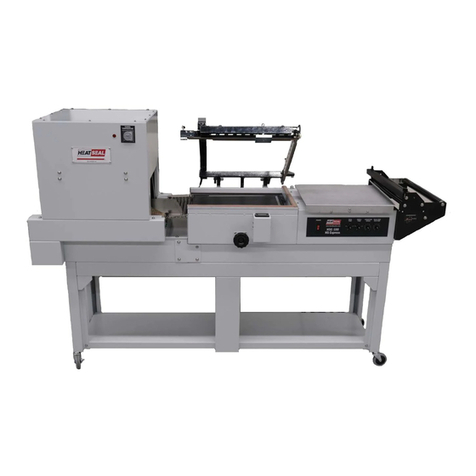
Heat Seal HDX-250 User manual

READ ALL INSTRUCTIONS CAREFULLY BEFORE OPERATING EQUIPMENT
P/N: MPT-FM111177A REV.0
OPERATING MANUAL
HDX-250 AUTOMATIC COMBINATION SHRINK SYSTEM

2
TABLE OF CONTENTS
Preface……………………………………………………………………………………….3
Safety ........................................................................................................................4
Warnings
Personnel Protective Equipment
Guarding
Operating Risks
Machine Installation……………………………………………………………………….8
Unpacking the System
Electrical connections
Film and Product Sizing ........................................................................................14
Maximum Product Size
Prohibited Products
Calculating Film Width
Machine Controls (Layout and Description) ........................................................15
Main Switch
Touchscreen
Emergency Stop Buttons
Reset
Bypass Safety Protections
USB connection
Machine Controls (Touchscreen)..........................................................................16
Home Page
Choose the Language
Password
Machine Parameters
Load a Program
Create a New Program
Touchscreen Parameters
Deleting a Program
Turning Off the Machine
List of Alarms .........................................................................................................24
Machine Setup and Adjustments ..........................................................................26
Loading Film
Conveyor Adjustments
Packaging
Maintenance............................................................................................................36
Warnings
Recommended Schedule

3
PREFACE
This manual gives instruction for the proper use of the machine. Keep it near the machine in place that
is known to all users. The manual is essential for safety.
This machine is an automatic packaging machine designed to package a single item, or a group of items
using center-folded shrink film. A few examples of products packaged are: food items, housewares, and
toys. This machine can be operated in two modes, it can be fed manually by a qualified technician, or it
can be in series with other machines in automatic mode. In automatic mode the machine is controlled
by logic in its PLC.

4
SAFETY STANDARDS
It is extremely important to read this entire section as it contains important information regarding risks
that personnel are subject to in the event of incorrect use of the machine. These basic standards must
be observed as well as specific standards applicable in the country of installation.
The machine must be installed by trained and authorised technicians.
This machine is not intended for use by persons (including children) with reduced physical, sensory
or mental capabilities, or lack experience and knowledge, unless they have been given supervision
or instruction concerning use of the machine by a person responsible for their safety.
Never use the machine for purposes other than as specified in the sales contract.
Never allow unauthorized personnel to perform repairs or other operations on the machinery.
The operator must be familiar with all warnings related to the tasks in hand and always be informed
by the head of the site regarding risks.
Ensure that all clothing is tight fitting, with particular reference to cuffs or other loose clothing.
It is forbidden to wear bracelets and loose accessories that can get entangled in the belts.
Ensure that all operating areas and transit zones are kept clear, clean and adequately lit at all times.
Eliminate all safety hazard conditions before using the machine and always notify the head
personnel of any malfunction.
Never use the machine in the event of fault.
Never tamper with safety devices or circuits.
Never perform modifications on the machine without prior authorization from the manufacturer.
If the supply cord is damaged, it must be replaced by the manufacturer, its service agent or similarly
qualified persons in order to avoid a hazard.
The electrical enclosure must remain closed during operation.
The key to open the electrical enclosure must be kept by a specialized and authorized member of
personnel.
Smoking is forbidden while the machine is operating!
Never performs maintenance and/or adjustments to the machine during operation. Guards may
only be disassembled by suitably trained and qualified maintenance engineers.
Never operate the machine without all guards fitted. Ensure correct position of all guards before
resuming normal operation.
The manufacturer declines all liability for damage or physical injury caused by failure to observe
safety standards.
CAUTION!
This machine is NOT designed for explosion-proof applications; it is a standard model and therefore must
never be installed or operated in zones subject to the risk of explosion.

5
SAFETY STANDSARDS
DESCRIPTION OF SAFETY STICKERS:
On machine front panel.
Danger of electrocution!
Risk due to presence of electrical power in electrical system inside panel.
When the panel is opened, the machine must be switched off and the plug must be pulled from the socket
of the main circuit.
While the machine is running, the panel must be mounted properly.
On the sealing bar frame.
At the shrink tunnel infeed and outfeed.
ATTENTION! Hot members. It shows the danger of burning, thus involving the risk of a serious
accident for the exposed person.
At the conveyor belt infeed and outfeed.
Dragging hazard!
Hazard generated by moving elements (conveyor belts, motor driven rollers) in the event of contact during
operation phases.
In the product loading area on the infeed belt.
Wear safety shoes that protect feet from impacts, crushing and compression while moving or handling the
machine.
Wear safety gloves that protect the hands from crushing and mechanical hazards and while moving or
handling the machine.
Wear safety gloves that protect the hands against the specific risks associated with the materials to be
packed (mechanical, chemical) and against coming into contact with the high temperatures present on the
seals and/or sealing blade (up to 200°C).
Wear safety gloves that prevent the hands from coming into contact with foodstuffs when
packaging them.

6
SAFETY STANDARDS
The machine is equipped with 2 front guard doors (C1) and (C2).
If one of the doors is opened, the machine stops and the “alarms” button on the display becomes red.
To reset machine operation, close the door and press the RESET (S2) button. The “alarms” button be-
comes green.
There are also 2 emergency stop buttons, see page 10.

7
SAFETY STANDARDS
Comply with the following prohibitions and warnings.
Dragging hazard!
Hazard generated by moving elements (conveyor belts, motor driven rollers) in the event of contact during
operation phases.
Burn hazard!
Risk due to high temperature of the sealing bar.
Do not touch the bar.
Risk due to high temperature inside the shrink tunnel.
Do not place your hands inside the tunnel.
Before performing operations in these zones, set the machine to “maintenance mode”, and wait for heaters
to cool.
Electric shock hazard!
Electric control board: risk due to electric energy inside electrical control board (upstream from the main
switch).
Before performing maintenance:
switch the machine off by rotating the main switch (Q1) to “0” (OFF)
remove the plug from the mains socket
WAIT 15 minutes to allow the capacitors to discharge.
The casters must be used only for moving the unit short distances across smooth, level floors.
Make sure the film roll is properly seated in its place.
Danger of placing hands inside!
Danger caused by placing hands in the product loading area on the infeed belt.

8
MACHINE INSTALLATION
Technical data
Shipping size: 2940 x 1440 x 1985 mm (116 x 57 x 78 inches)
Shipping weight: 878 kg (1935 lbs)
Machine weight: 710 kg ( 1565 lbs)
Machine Layout

9
MACHINE INSTALLATION
Transport and positioning
Cut the strap with scissors make sure you protect your eyes by wearing glasses and withdraw the cardboard. Remove the
hardware intended to fasten the machine to the pallet.
Accessories
Check the following is present inside the packaging:
instructions
2 keys for the “SAFETY DEVICE EXCLUSION” (E) selector
maintenance box
1 film support rod Ø6 – lg. 740 mm (triangle unit – pos. 1)
1 film support flap (triangle unit – pos. 2)
1 film opening rod Ø10 – lg.730mm (unwinder unit – pos. 3)
2 rollers (tunnel belt – pos. 4).
Wear safety shoes that protect feet from impacts, crushing and compression while moving or handling the
machine.
Wear safety gloves that protect the hands from crushing and mechanical hazards and while moving or
handling the machine.
Handle with great care during transport and positioning!
Before any movement, make sure that the lifting means is suitable for the load to be lifted!
CAUTION!
The machine is shipped with 2 cross-beams (T) mounted at the front and rear.
We recommend always using these cross-beams whenever the machine is lifted with a forklift.
Lift the machine from the pallet by using a fork lift truck.
For the machine lifting, place the lift truck forks up to the point stated on the specific label applied on the
machine.

10
MACHINE INSTALLATION
Environmental conditions
Place the machine level on the floor in a suitable environment free from humidity, gases, explosives, combustible materials. The
machine may only be installed on smooth, flat non-inflammable surfaces.
Working environment conditions:
Temperature from + 5°C to + 40°C (41 to 104°F)
Relative humidity from 30% to 90%, without condensation.
The lighting of the operation room shall comply with the laws in force in the country where the machine is installed. However, it shall
be uniform and allow good visibility in order to safeguard the operator’s safety and health.
MACHINE PROTECTION FACTOR = IP20
THE AIRBORNE NOISE MADE BY THE MACHINE IS LOWER THAN 70 dB(A)
Electrical connections
Voltage (V): see data on plate
Frequency (Hz): see data on plate
Maximum absorbed power (W): see data on plate
Maximum absorbed current (A): see data on plate
Note: when contacting the Manufacturer, always indicate the model and the serial number
specified on the plate on the rear part of the machine.
The power line must be protected with a type B residual current device with rated residual current equal to
“IΔn”, 30 mA.
As a result, the maximum resistance of the earth electrode must correspond to the values indicated in the
following table
IΔnMaximum resistance of the earth electrode
(50 V) (25 V)
3 A 16 Ω8 Ω
1 A 50 Ω25 Ω
500 mA 100 Ω50 Ω
300 mA 166 Ω83 Ω
30 mA 1666 Ω833 Ω
OBSERVE HEALTH AND SAFETY REGULATIONS!
If the machine is not equipped with the power supply plug, use a plug that is suitable for the
voltage and amperage values described by the rating plate and that can comply with the
rules in force in the installation country.
GROUNDING OF THE UNIT IS OBLIGATORY!
Before executing electrical connections, make sure the mains voltage matches the one on
the plate on machine rear and that the ground contact complies with the safety rules in force.
In case of doubts about the mains voltage, contact the local public supply Company.
Insert the plug on the cable from machine electrical cabinet in a mains power supply socket
that can be reached easily by the operator.

11
MACHINE INSTALLATION
Controlling the rotation direction
After electrically connecting the machine and before turning it on, make sure you follow these instructions to check the
exact direction of rotation:
Turn the main switch (Q1) to position 1.
The display comes on and the screen with the "company" logo appears.
Press the “RESET” (S2) button, then the logo.
The home page will be displayed.
Press the start cycle key .
Press and check that the conveyor belts rotate in the direction
shown in the figure (from right to left).
Otherwise, invert two of the three phases in the plug (Attention: do not
invert the neutral wire!).
The rotation direction must be checked every time the power socket is changed!

12
MACHINE INSTALLATION
Positioning the accessories
Put the film support rod (1) and the film support flap (2) on the triangle unit.
Position the film opening rod (3) on the unwinder unit.
Rounded end

13
MACHINE INSTALLATION
Place the 2 rollers (4) at the exit of the tunnel belt.
Remove the wire blocking the tunnel belt.

14
FILM AND PRODUCT SIZING
Max product size:
a = 16.54 in (420mm) b = 15.75 in (400mm) c = 4.73 in (120mm)
This machine is capable of packaging a wide variety of products. It is used successfully in these pro-
duction environments: food, marketing, graphics and mailing, high volume industry, and fabrics.
The products listed below must absolutely not be wrapped to avoid permanent damage to the machine
and serious injuries to the operator:
Wet and unstable products
Liquids of any kind and density in fragile containers
Flammable and explosive materials
Pressurized gas cylinder of any kind
Loose and volatile powders
Any materials and products not listed but which might harm operator and damage the machine.
A = 27.56 in (700mm) MAX
D = 9.85 in (250mm) MAX
Film:
This machine is designed to use polyolefin shrink film between
40 Ga (9 micron) and 150 Ga (38 micron).
Consult the MSDS of the films in use and follow the
corresponding instructions.
Film width calculation:
A = b +c +3.94 in (100mm)
Note: it may be necessary to add more than 3.94 in for tall
products, or products of complex shape.

15
MACHINE CONTROLS
(LAYOUT AND DESCRIPTION):
Q1 Main switch
Turns the machine on and off.
DTouchscreen Display
Displays selected functions and settings.
S1.1 Emergency Stop Buttons
S1.2 These 2 buttons stop the machine in case of immediate danger. If they are pressed, they need
to be turned clockwise to release them.
S2 Reset button
Press the reset button to clear an emergency stop.
S3 “Bypass Safety Protections” selector
If this is set to OFF, the machine will only run an automatic program if the guard doors are closed.
If this is set to ON, the machine may be operated with the guard doors open. This condition is
necessary only during setup and loading the film.
XUSB Connection– for data transfer to the controller.
Only use one finger to navigate the
touchscreen. If two or more points
are pressed at the same time you
may select an unintended item.

16
MACHINE CONTROLS
(TOUCHSCREEN):
Turn the main switch (Q1) to position 1.
The display comes on and the screen with the company logo appears.
Press the logo, then press the “reset” (S2) button.
The home page will be displayed.
Home page
The home page displays information for important areas of the machine.
“Shrink tunnel” parameters
“Sealing bars” parameters
✱Film parameters (only dis-
played in AUTOMATIC mode)
✱ ✱
Settings page key
Programs quick load keys
✱Shrink tunnel heater on/off keys
✱ ✱ Cycle start/stop keys
Automatic Key
Manual Key
Alarms Key
Set-up Key
Settings page
Press from the home page to access the settings page after having entered the password.
Program Name
Key to display
list of programs
List of variables
“Settings page” key
“Load program from USB” key
“Save program on USB” key
“Home page” key
“Save program” key
“Load program” key
“Save active parameters in the se-
lected program” key
“New program” key
“Delete program” key

17
MACHINE CONTROLS
(TOUCHSCREEN):
Configurations page
The configurations page can be accessed from the home page by pressing .
“Default parameters” key
“Optional” key
“Manual controls” key
“Service menu” key
Seal Jaw “Homing” key
“Language settings” key
“Touchscreen parameters” key
“Logout” key
Data Entry Keyboard
The keyboard is displayed when the value of a variable needs to be entered or changed.
Value to be entered
Confirm key
Choose the Language
Press Press
It displays the list of
languages: Press the key
of the desired language,
then press

18
MACHINE CONTROLS
(TOUCHSCREEN):
Manual Mode
The machine is always in manual mode when started (powered on).
Press to enable Manual mode.
To enable Manual program controls, press the
start cycle key.
The screen will display the “sealing” and
“belt movement” controls.
Sealing
Pressing this key to performs a single seal cycle.
Belt movement
The following items move for as long at this key is
pressed: infeed belt, sealing belt, film unwind and
film rewind.
The MANUAL mode is the condition required for the set-up and film loading and film unloading.
In this mode, it is possible to open guards (C1) and (C2) by turning the key selector (S3) to an ON position.
By turning the selector (S3) to the OFF position, the alarm is reset.
With the guards open (after pressing the start cycle key ), only is active.
Automatic Mode
This is the completely automatic machine operating condition.
Press to enable Automatic mode.
Press the start cycle key to start the automatic cycle.

19
MACHINE CONTROLS
(TOUCHSCREEN):
Password
Some functions are password protected to ensure the operator does not erroneously modify the PLC
program. There are 3 levels of password protection, each has a different user name and password.
Operator (first level)
Maintenance technician (second level)
Manufacturer (third level)
The padlock symbol next to a key indicates it is password protected.
Operator Password (first level)
With this password enabled, it is not possible to save changes to program variables.
password
(first level)
password
(first level)
Maintenance Technician and Manufacturer Password (second and third levels)
password
(third level)
password
(second level)
Operator Login
Press the password
protected key
Enter the user name and
password, press Login
Note: the padlock symbol
disappears
Logging Out
From the home page
screen, press Press
The padlock symbol
reappears indicating the
program is password
protected.

20
MACHINE CONTROLS
(TOUCHSCREEN):
Parameters
The parameters of a program can be adjusted from both the home page and the settings page.
Shrink Tunnel
The parameters that can be adjusted are the tunnel temperature and the conveyor belt speed. To
modify a set point press the number (165°C or 40%)- the data entry keyboard (see p. 12) will appear, set
the new value and press “Ent”.
Tunnel temperature
(set point)
Tunnel temperature
(actual)
Belt speed
(set point)
Tunnel heater on/off keys:
If the screen displays
the heater is on.
If the screen displays
the heater has
reached the 90°C
minimum.
The color of the thermometer has meaning: red means the tunnel has yet to reach the set point,
green means the tunnel is at the set point, blue means the tunnel is in a cooling phase.
Infeed and Sealing
The parameters that can be adjusted are:
Seal bar temperature
Seal time
Seal jaw opening distance
Seal jaw pressure
Seal cool time
Infeed belt
Seal bar temperature
(set point)
Seal jaw opening
distance
Seal jaw pressure
Seal time
(set point)
To modify these values– press anywhere on the screen to access the settings page.
Table of contents
Other Heat Seal Industrial Equipment manuals
Popular Industrial Equipment manuals by other brands
ABB
ABB HT562264 Operation manual
SENSY
SENSY 5950 Series installation manual

Anest Iwata
Anest Iwata PET-10N Use and maintenance instruction manual

Eaton
Eaton Cooper Power VFI SF6 Installation, operation and maintenance instructions

Full Spectrum Laser
Full Spectrum Laser MUSE TITAN V3 manual
ABB
ABB HT563146 Operation manual
