SENSY 5950 Series User manual
MA-5950_EN.doc Page 1 on 15 Rev: 29-03-19
5950 LOAD CELL SERIES
INSTALLATION MANUAL
1. GENERAL INFORMATION ......................................................................................................................................................................................... 2
1.1. Placement at level ..............................................................................................................................................................................................2
1.2. Shocks, vibrations and overloads....................................................................................................................................................................... 2
1.3. Electrical weldings .............................................................................................................................................................................................. 2
1.4. Lightning ............................................................................................................................................................................................................. 2
1.5. Exterior mechanical influences...........................................................................................................................................................................3
1.6. Setting of the counter force ................................................................................................................................................................................ 3
2. CABLing ......................................................................................................................................................................................................................3
2.1. Cable ..................................................................................................................................................................................................................3
2.2. Wiring..................................................................................................................................................................................................................4
2.3. Parallel wiring .....................................................................................................................................................................................................4
2.4. Calibration........................................................................................................................................................................................................... 4
2.5. Measurement errors ........................................................................................................................................................................................... 5
2.6. Insulation test...................................................................................................................................................................................................... 5
2.7. Output impedance ..............................................................................................................................................................................................6
2.8. Input impedance ................................................................................................................................................................................................. 6
3. MOUNTING WITH EASY MOUNT.............................................................................................................................................................................. 7
3.1. Mounting with 3 load cells ..................................................................................................................................................................................7
3.2. Mounting with more than 3 loadcells: ................................................................................................................................................................. 7
4. example of mounting without easy mount ................................................................................................................................................................... 8
4.1. Mounting with a rubber foot (F5950) .................................................................................................................................................................. 8
4.2. Mounting with a solid steel base (A5950)........................................................................................................................................................... 8
5. USE IN POTENTIALLY EXPLOSIVE ATMOSPHERE (OPTION) .............................................................................................................................. 9
5.1. Intrinsic safety protection.................................................................................................................................................................................... 9
6. Periodic inspections.....................................................................................................................................................................................................9
7. Use features .............................................................................................................................................................................................................. 10
8. Guarantee.................................................................................................................................................................................................................. 10
9. DRAWINGS AND WIRING DIAGRAMS ................................................................................................................................................................... 10
10. EU Declaration of Conformity.................................................................................................................................................................................. 15
MA-5950_EN.doc Page 2 on 15 Rev: 29-03-19
1. GENERAL INFORMATION
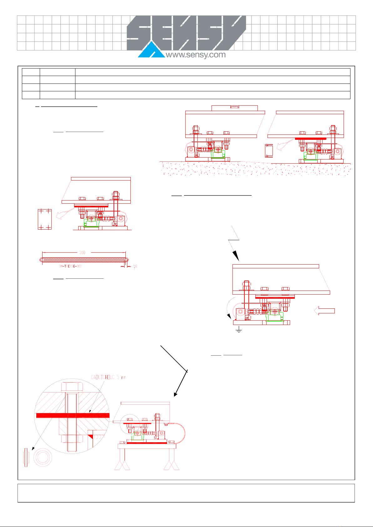
1.1. Placement at level
This operation guarantees a good distribution of the loads
and the uprightness of the effort.
Make sure you check the placement at level of the
sensors and of the supporting parts. Use wedges for
thickness if necessary.
1.2. Shocks, vibrations and overloads
The sensor can take overloads of 150% without being damaged.
If it is likely to undergo shocks and vibrations, you need to mount it with a shock absorber
and it is sometimes necessary to oversize the sensor.
1.3. Electrical weldings
When arc welding must be done on the structure, it would be advised to install
stranded ground wire in order that the derived current could not pass through the cell,
damaging it. It would also be advised to disconnect the cells of the measuring
instrument.
1.4. Lightning
If there is a risk of lightning, it would be advised to isolate the cell
completely and derive the current through the stranded wire.
In order to do that, place a rubber sheet, ceramics or other forms of
insulation underneath the sole and polyamide waterproof washers
under the fixing screws.
Rev.
Date
Reason
1
29/03/2019
Adding points : 5, 6 ,7, 8, 9 and 10-EU Declaration of conformity
Stranded ground wire directly linking the structure to the earth.

MA-5950_EN.doc Page 3 on 15 Rev: 29-03-19
1.5. Exterior mechanical influences
In order to avoid measurement errors, the load to be
weighed must not be subject to parasitic contributions: if
there are any connecting pipes, cables and balls or draw-
bolts, they must be installed with THE GREATEST
FLEXIBILITY. Also, ladders or bridges for access will be
suitably articulated (clamping).
1.6. Setting of the counter force
This setting has to be done whilst the sensor is UNLOADED.
By hand, bring the nut 1 mm away from the structure, then screw B
to A.
Finally, using a key, block A onto B so as not to exert any effort on
the sensor.
2. CABLING
2.1. Cable
The cells are delivered with a 4-wire screened cable.
The screen (shielded cable) cannot in any case be in contact with the
ground, e.g.; in metallic junction boxes, it is necessary to isolate the screen
with a sheath (thermal).
The screen can only be connected to standardized earth.
It is advised to install a thermo-retractable sheath (retracted 4x) at the end of
the cable inside a waterproof paste, in order to avoid any leak. If there is any
possible danger of damage along its wiring, it is necessary to use an
additional cable protection, passing the cable through a pipe (steel,
preferably).
COLOR CODE
1) Excitation- (Yellow)
2) Excitation+ (Brown)
3) Signal+ (Green)
4) Signal- (White)
5) Screen
A) Cable PVC
B) Thermo-retractable
sheath
MA-5950_EN.doc Page 4 on 15 Rev: 29-03-19
2.2. Wiring
The cell wiring should be far away from power lines (motors, transformers)
and placed in separate pipes. Soldered connections have to be applied in
the junction box, (preferably screwed connections). It is advised to place a
bag of SILICA GEL to keep dry inside the junction box. SENSY could
provide PVC junction box with a PG9 packing-gland, which could receive 4
or 6 parallel cells. REF: Junction box
JBOX-4R (4 inputs - 1 output)
JBOX-6R (6 inputs - 1 output)
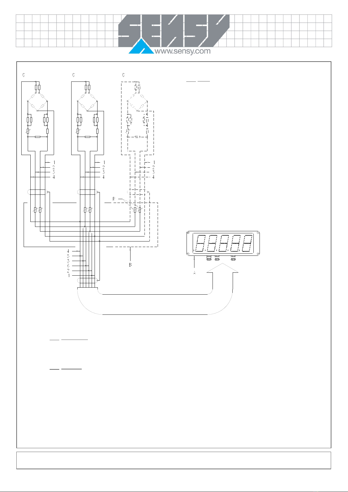
2.3. Parallel wiring
The cells must be installed in parallel, with the stranded mass wire joined to it. The sense must be joined to the cell supply, before the points of
parallel wiring and the stabilising resistances.
2.4. Calibration
It must be done after the sensor has been turned on for a while (10-15 minutes) to obtain a uniform temperature of the installation. The cells do not
usually need to be adjusted with each other. However, when greater precision is needed, it is sometimes necessary to stabilise the cells individually
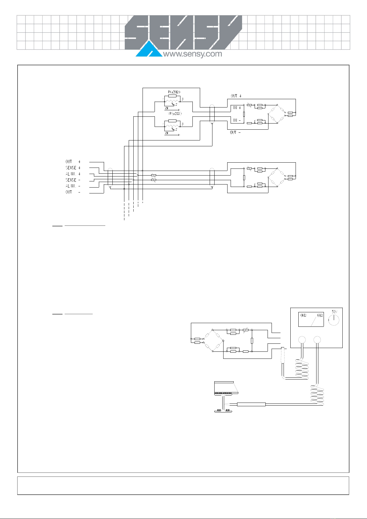
with the resistances in the junction box. Those resistances are of several ohms (±10) and are installed in the supply circuit. A parallel adjustable
resistance is mounted with a fixed resistance. The most sensitive cell will have its input resistance increased and the least sensitive will have its
lowest input resistance. You will see that it is preferable to work on both supply cables: schematic mounting is given for your information and allows
a variation of 0 to 20 ohms in series on the input impedance (2x10 ohms).
Note: A well known weight of more than 20% of the nominal load of the system can be expected. The calibration error is always much higher than
the error made on the evaluation of the load.
A) Display (ex. Dv680)
B) Junction box
C) Cell
R) Adjusting resistance
1) – out measure (green)
2) – in supply (yellow)
3) + in supply (brown)
4) + out measure (green)
5) Ref. (sense) + (pink)
6) Ref. (sense) + (grey)
MA-5950_EN.doc Page 5 on 15 Rev: 29-03-19
2.5. Measurement errors
When the calibration is difficult and measurement errors are observed, it is necessary to check the installation. Mechanically, the cells must be free
in the direction of the load and well positioned. Electrically, the connections must be securing, the junction boxes exempt from humidity and the
cables intact. If there is no fault to be seen, it is necessary to verify the internal circuit.
SENSY can help to diagnose based on the associated diagnosis sheet provided in the appendix and filled in beforehand.
2.6. Insulation test
The measuring of the insulating resistance is done with a multimeter. The
standardized testing voltage is 10 V. It is applied to a conductor. It can be
determined by disconnecting the measuring instrument and applying
voltage between one of the conductors and the metallic mounting
structure – or individually, cell by cell, to locate the leakage with precision.
The insulation must not, in any case, be lower than 2 GΩfor a 10 V
voltage. This insulation default will generate measurement errors if the
insulation resistance is lower than several hundred MΩ. Insulation default
can also be generated by environmental conditions (temperature,
humidity).

MA-5950_EN.doc Page 6 on 15 Rev: 29-03-19
2.7. Output impedance
The Wheatstone bridge is made up of 350 Ωgauges.
At the output signal (OUT+: green, OUT-: white), the resistance is 700 Ω± 5 Ω.
This impedance must be in accordance with the individual cell data sheet, which could easily be determined with a multimeter.
If a wider varying resistance is read, it means that there is a break-off or a short circuit current a resistance variation of several
ohms would instead be a consequence of a severe overvoltage problem.
2.8. Input impedance
Input signal (IN+: brown, IN-: yellow): its resistance is usually of 700 Ω± 5 Ω, its impedance must be in accordance with
the individual cell data sheet. If a different resistance is read, it means that there is a break-off or a short circuit current. It
is at the input that one finds drift compensation, slope and sensitivity adjusted resistance.
Rm Sensitivity drift compensation
Rms Sensitivity drift adjustment
Rs Sensitivity calibration
Rzb Zero calibration
Rzc Zero drift compensation

MA-5950_EN.doc Page 7 on 15 Rev: 29-03-19
I5950
M5950
I5950
I5950
I5950
I5950 I5950
I5950
M5950
3. MOUNTING WITH EASY MOUNT
The EASY MOUNT incorporates the fixing plates, the support parts, the counter force and the
anti-rotation (displacement) in one direction. This kit with ball joint absorbs forces of up to 20 kN
in the direction X and leaves enough freedom of movement in the direction Z for dilatations.
CAUTION: this kit of assembly does not rigidify the assembly overall and does not allow to
catch up possible buckling of foot. These feet must thus be dimensioned consequently to avoid
any risk of buckling following deformation or slight rotation of the body of silo.
3.1. Mounting with 3 load cells
This mounting offers the best properties for he distribution of loads and freedom for the
dilations of the part to be weighed.
3.2. Mounting with more than 3 loadcells:
When more than 3 load cells are used, each one must be placed at the same level to obtain a good equivalent load distribution. Each load cells
output signals and the empty part to be weighed must be identical (case of a symmetrical part).
So, to avoid cramping the displacements (dilatation) of the part to be weighed, use only 3 I5950; for the fourth load cells, use the M5950 mounting
kit. If dimensional variations are weak, use a mounting with 4 x I5950, giving better characteristics in order to stand up to parasite efforts.
Note: The characteristics of the sensors are guaranteed between –10°C and 45°C without thermal gradient at the level of the sensor and rapid
variation of the temperature, use a protective screen insulated to form a barrier between the source of the heat and the load cells (sun, wind,
thermal radiation, conduction).
MA-5950_EN.doc Page 8 on 15 Rev: 29-03-19
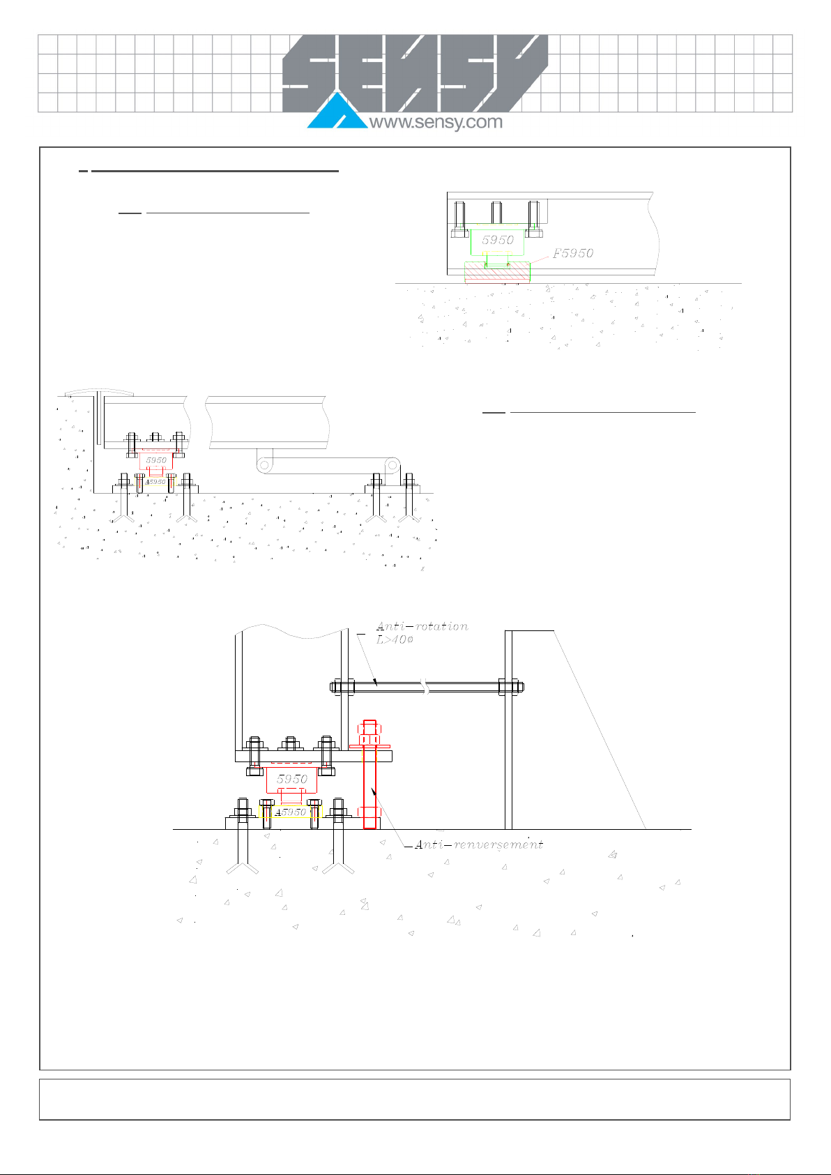
4. EXAMPLE OF MOUNTING WITHOUT EASY MOUNT
4.1. Mounting with a rubber foot (F5950)
This mounting allows the sensor to be put straight on a levelled
ground.
The rubber allows to absorb the shocks and the slights
irregularities of the state of the ground surface.
4.2. Mounting with a solid steel base (A5950)
This combination gives an easy solution for the installation when
the anti-rotation and counter force parts are incorporated to the
structure. The A5950 base has the necessary solidity to support the
head of the sensor and allows it to move freely (in the case of great
dilatation, for example).

MA-5950_EN.doc Page 9 on 15 Rev: 29-03-19
5. USE IN POTENTIALLY EXPLOSIVE ATMOSPHERE (OPTION)
5.1. Intrinsic safety protection
Use of sensors in hazardous zones can only be done with Ex marked sensors, delivered with one or more of the
certificates hereunder:
ATEX: ISSeP07ATEX012X
SENSY’s load cells which are marked Ex i comply with the following standards:
ATEX
EN 60079-0: 2012
EN 60079-26: 2007
EN 60079-11: 2012
The use of junction boxes or additional cable lengths must be considered in the choice of protection. The electrical characteristics of the cable
being limited (see certification), it is recommended to carefully chose the cable length and avoid any winding of the cable. After having defined all
elements, it is mandatory to control if the sensor’s output tension is still compatible with the electronic device in use and the requested accuracy.
See certificate for the special conditions for safe use.
6. PERIODIC INSPECTIONS
1. Check output for zero load (annually)
Output signal
Min acceptable
Max acceptable
mV/V / 4 wires
-0.15 mV/V
0.15 mV/V
4-20mA / 2 wires
3 mA
6 mA
4-20mA / 3 wires
3 mA
6 mA
0- 5V / 3 wires
0 V
0.8 V
0- 10V / 3 wires
0 V
0.8 V
1-5V / 3 wires
0.5 V
1.5 V
1 -10V / 3 wires
0.5 V
1.5 V
-10 / 0 / + 10V
-1.5 V
1.5 V
2. Make sure that the axle beam has not been knocked (markings) or chemically attacked (some corrosive greases). If points 1 and 2 are not
accounted for, just take preventive measures. (annually)
3. In case of doubt, reply to the diagnostic questionnaire available on Web: www.sensy.com/support.
4. Verify the integrity of the cable.
5. After any serious functioning incident, repeat operations 1 to 4.

MA-5950_EN.doc Page 10 on 15 Rev: 29-03-19
7. USE FEATURES
(The exact characteristics are systematically given in the control sheet delivered with every load cell and function of the output signal!)
Output signal:
mV/V
4-20 mA
4-20 mA
1-5 V
0-10 V
-10…0…+10 V
RS-232
RS-485
2 wires
3 wires
3 wires
3 wires
3 wires
Compensated temp. range
-10…+45°C
Operating temperature range
-30… +70°C1
Storage temperature range
-50…+85°C
-50…+85°C
Power supply
(VDC)
5…10…152
9 – 303
13 – 30
13 – 30
15 - 184
6…12…18
Load impedan
ce
e
(Ω)
NA
≤750
≤ 1.000
> 5k
Nominal sig. range
0 – 1…2 mV/V
4 - 20 mA
4 - 20 mA
0.1-5 V
0.1-10 V
-10…0…+10 V
Saturation
> 3 mV/V
> 24 mA
> 24 mA
> 11 V
1Max +60°C for EX-I T4, T6 and C6 options
25 to 12VDC for EX-I T2 GD, EX-I T4 GD and EX-I T6 GD options
39-28VDC for EX-I C6 options
415 to 27VDC with a 1000 Ωbridge
8. GUARANTEE
The manufacturer’s guarantee is applicable as far as mounting recommendations and general use principle, like above described, are respected.
For any particular use, not described in this document, it is mandatory to obtain a prior written agreement from SENSY S.A. for the validity of the
guarantee.
9. DRAWINGS AND WIRING DIAGRAMS

Ref. Item Capacities ØA D H S T ØE RR
Max. Deflexion (mm) Weight (kg)
5950-A 0.3 - 5 t 54.5 38.5 54 62.9 7 89 60 0.04 - 0.07
±1.4
5950-B 7.5 - 15 t 59 38.5 54 62.9 7 89 60 0.08 - 0.15 ±1.4
5950-C 20 t 59 38.5 54 62.9 7 89 60 0.2
±1.4
Rev. 18/04/2018
Accessories
Other capacities and dimensions available on request
Load direction
Wiring
Dimensions in mm
·
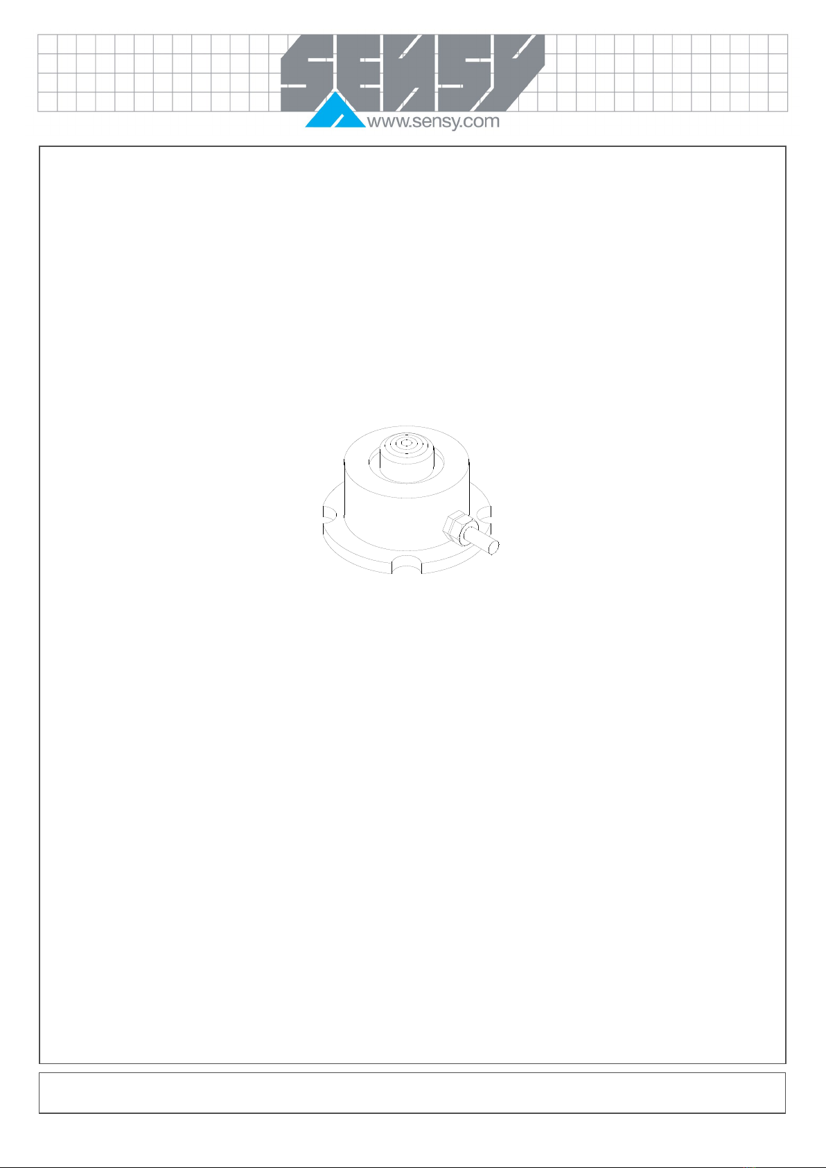
STANDARD DIMENSIONS5950 >
TECHNICAL DRAWINGS: LOW-PROFILE COMPRESSION LOAD CELLS
on request
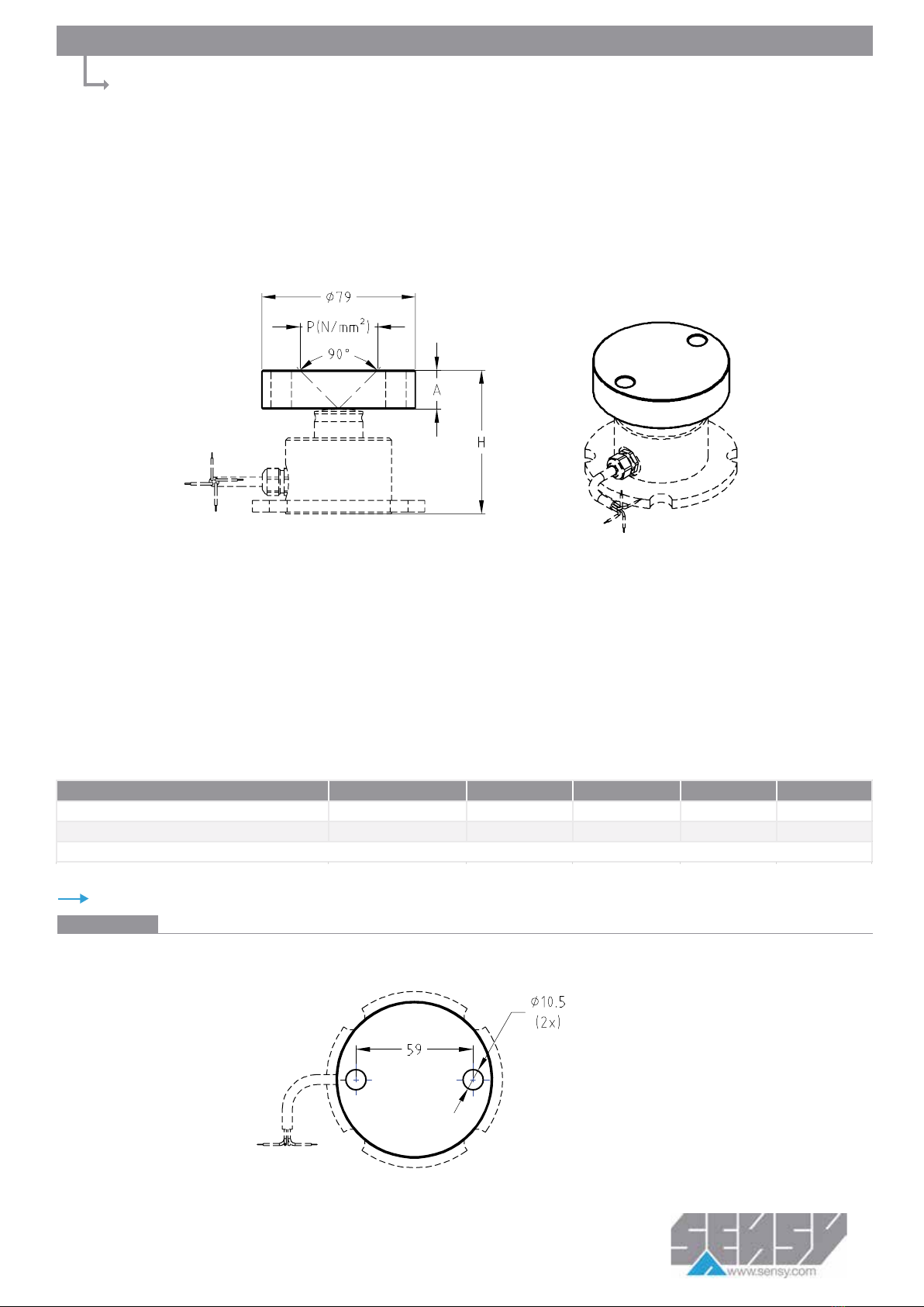
Ref. Item* Capacities
A H P N/mm² Weight (kg)
A5950-AB 0.3 - 15 t 20 74 ± 120 (15 t) ± 0.76
A5950-C 20 t 25 79 ± 100 ± 0.95
*Material: stainless steel
Other view
Other capacities and dimensions available on request
STANDARD DIMENSIONS
A5950 >
Dimensions in mm
TECHNICAL DRAWINGS: LOADING PLATES FOR 5950
Rev. 16/04/2018
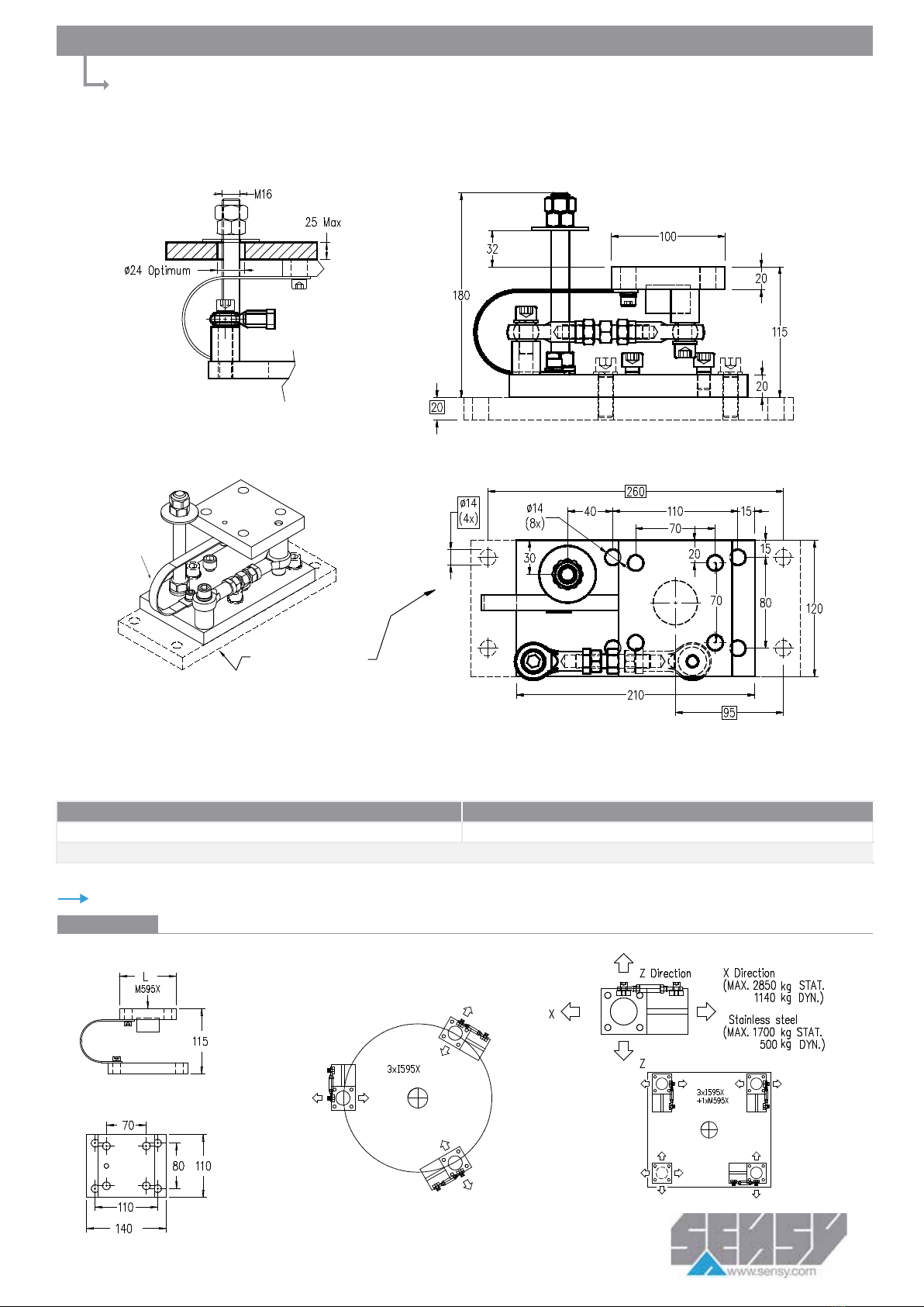
STANDARD DIMENSIONS
I5950-I5955 >
Dimensions in mm
Ref. Item* Capacities
I595x-A 0.3 - 20 t
*x=Material: I5950 - stainless steel; I5955 - alloy steel
E
lectrical
g
round strap
ACCESS-I595x-SEM
Other views
Other capacities and dimensions available on request
TECHNICAL DRAWINGS: EASY MOUNT FOR 5950
Rev. 01/06/2018

Other view
Other capacities and dimensions available on request
Electrical
ground strap
Ref. Item* Capacities
M595x-A 0.3 - 20 t
*Material: M5950 - stainless steel; M5955 - alloy steel
STANDARD DIMENSIONS
M5950 >
Dimensions in mm
·
Rev. 16/04/2018
TECHNICAL DRAWINGS: MOUNTING PLATES FOR 5950

MA-5950_EN.doc Page 15 on 15 Rev: 29-03-19
10. EU DECLARATION OF CONFORMITY
Manufactured by:
SENSY SA
Z.I. Jumet – Allée Centrale
B – 6040 JUMET
Phone: +32 71 25.82.00
Fax: +32 71 37.09.11
Website: http://www.sensy.com
CONCERNED ITEMS: 5950, see calibration certificate related to model and serial number.
SENSY S.A. certify that the items described here above have been duly designed, manufactured and tested for use in accordance
with the essential requirements defined in the European Directives listed here under.
2014/30/EU Electro-Magnetic Compatibility Directive
2011/65/EU Restriction of the use of certain hazardous substances in the electrical and electronic equipment
(RoHS)
2014/35/EU Safety / low voltage directive
Conception and compliance of this equipment is made according to all of part of the following standards:
EN 61326 (2006)
If designed, manufactured and tested safety ref. D-DP SIL3 READY (option):
see specific and separate certificate according to ISO 13849-1 and/or EN 62061
If designed, manufactured and tested for use in potentially explosive atmospheres (option):
see specific and separate certificate.
Jumet,
March 29th 2019
Augustin DUBOIS
Product Development Division
Table of contents


