Heatcraft Bohn PRO3 User manual

BN-H-IM-81E
|
FEBRUARY 2020
Part# 25002301
PRO3TOP MOUNT PACKAGED
REFRIGERATION SYSTEM
Installation and Operations Manual
For Indoor Applications

PRO3TOP MOUNT PACKAGED REFRIGERATION SYSTEM
2
TABLE OF CONTENTS
Dimensional Drawings
3
Space and Location Requirements
4
Recommended Unit Placement
5
Scroll Compressor Models
5Indoor Models
6Rigging/Access Requirements
6Mounting
6Inspection
6General Safety Information
6Standard Installation Procedure
7Changing the Ezy
Refrigeration/Defrost Sequence of Operation
8
8Low Temperature Models/Ezy Setting 1
9Medium Temperature Electric Models/Ezy Setting 2
9Medium Temperature Air Models/Ezy Setting 3
Programming the PJEZC Carel Electronic Controller
10
10 Installation and Removal
11 Electrical Connections
11 Controller Wiring
11 Display
12 Keypads
12 Preliminary Configurations
12 Keypad Functions
13 Temperature Display
13 Temperature Control
14 Rapid Parameter Set Selection
14 Alarms and Signals Table
15 Main Signals and Alarms/Data Error
16 Modifying and Setting Default Parameters
Troubleshooting
17
Device Set-up
18
Replacement Parts
20
Electrical Wiring Diagrams
21
21 Electric Defrost Systems/Single Phase P1 Cabinet
22 Air Defrost Systems/Single Phase P1 Cabinet
23 Electric Defrost Systems/Single Phase PT0027LBNEM
24 Electric Defrost Systems/Single Phase PT0046M*NEM
25 Air Defrost Systems/Single Phase PT0046M*NAM
26 Electric Defrost Systems/Single Phase P2 Cabinet
27 Air Defrost Systems/Single Phase P2 Cabinet
28 Electric Defrost Systems/Single Phase P3 Cabinet
29 Air Defrost Systems/Single Phase P3 Cabinet
30 Electric Defrost Systems/Three Phase P3 Cabinet
31 Air Defrost Systems/Three Phase P3 Cabinet
Warranty
32

3
DIMENSIONAL DRAWINGS
15.3"
(38.86 cm)
4"
10.16cm
14.1" (35.81 cm)
28.26" 71.77cm
20.4" (51.82 cm)
24.4" (61.98 cm)
FIGURE 1 - A CABINET DESIGN (INDOOR ONLY)
14.25" X 20.75" PANEL OPENING REQUIRED FOR EVAPORATOR SECTION OF "A" CABINET SIZES.
28.5" 72.4cm
24.75" (62.87 cm)
17.5"
(44.5 cm)
4"
(10.16 cm)
24.75" (62.84 cm)
52" (132 cm)
20"
50.9cm
FIGURE 2 - B CABINET DESIGN
25"X25" PANEL OPENING REQUIRED FOR EVAPORATOR SECTION OF "B" CABINET SIZES.
WITH WEATHERHOOD: 33.8" (85.85 cm)
*
* - 23.5" (59.69 cm) ON OUTDOOR MODELS WITH WEATHERHOOD
42" (106.7 cm)
38.25" (97.15 cm)
19"
(48.3 cm)
20"
50.8cm
24.75" (62.87 cm)
4"
(10.16 cm) 52" (132 cm)
FIGURE 3 - C CABINET DESIGN
25"X38.5" PANEL OPENING REQUIRED FOR EVAPORATOR SECTION OF "C" CABINET SIZES.
WITH WEATHERHOOD: 47.3" (120.14 cm)
*
* - 25.5" (64.77 cm) ON OUTDOOR MODELS WITH WEATHERHOOD
Figure A P1 Cabinet Design (indoor only)
14.25"x 20.75" panel opening required for evaporator section of “P” cabinet sizes.
*- 21.5" (54.61 cm) on outdoor models with weatherhood
25"x 25" panel opening required for evaporator section of “P2” cabinet sizes.
*- 23.5" (59.69 cm) on outdoor models with weatherhood
25"x 38.5" panel opening required for evaporator section of “P3” cabinet sizes.
Figure B P2 Cabinet Design
Figure C P3 Cabinet Design

PRO3TOP MOUNT PACKAGED REFRIGERATION SYSTEM
4
SPACE AND LOCATION REQUIREMENTS
FOR INDOOR MODELS
The most important consideration which must be
taken into account when deciding upon the location
of air-cooled equipment is the provision for a supply of
ambient air to the condensing unit. Ignoring this essential
requirement will result in higher condensing pressure
and contribute to poor operation or potential equipment
failure. Units must not be located in the vicinity of steam,
hot air or fume exhausts. Adequate air circulation through
the condensing unit is critical to ensure proper equipment
operation. Improper installation can damage the unit
and will void the warranty. PRO3penthouse-style
packaged units are designed for indoor use only
in ambient temperatures of S0°F to 100°F. The unit
cabinet is not approved for weather tight applications.
Another important consideration is that the unit should
be mounted away from noise sensitive spaces and
must have adequate support to avoid vibration and
noise transmission into the building. Storage should
not be allowed on top of walk-in structure. Unit must
not be enclosed in an unventilated space.
Side View Allow 2 feet clearance above
unit to remove top panela and
to allow service access.
Mounting rails may be used to attach
unit to ceiling. Throughbolts should be
insulated or non-conductive to prevent
sweating.
FIGURE 1
System Space and Location Requirements for INDOOR models

5
Top View
One PRO3System
Evaporator
Section
Compressor
Section
Evaporator
Airow
Top View
Two PRO3Systems
Indoor Models
W
Min.
W
Min.
2 x Width
Min.
Evaporator
Section
Compressor
Section
Evaporator
Section
Compressor
Section
W = Unit Width
Evaporator
Airow
Evaporator
Airow
RECOMMENDED UNIT PLACEMENT
FOR INDOOR MODELS
Some general rules for the evaporator section placement
which must be followed are:
1. Ensure that the structural integrity of the box can withstand
the weight of the top mounted equipment.
2. The air pattern must cover the entire room.
3. NEVER locate the evaporator section over doors.
4. Location of aisles, racks, etc. must be known.
5. Never remove or unlock any panel cam-locks to install
top mounted equipment.
The size and shape of the storage will generally determine
the type and number of units to be used and their location.
NOTE: Always avoid placement of
units directly above doors and door
openings.

PRO3TOP MOUNT PACKAGED REFRIGERATION SYSTEM
6
STANDARD INSTALLATION PROCEDURE
FOR INDOOR USE
1. Inspect packaging for shipping damage.
Open package and inspect unit for concealed damage.
2. Review the space and location requirements on page 4.
3..Provide a finished opening in the box ceiling, to the
appropriate dimensions and structural strength.
4. DO NOT remove or disengage any box cam-locks in
order to install the PRO3unit.
ACCESS REQUIREMENTS
Provide adequate space at the compressor end of the unit
for servicing. Provide two (2) feet of space above unit for
service.
RIGGING
Rigging holes are provided on all models. Caution should
be exercised when moving these units. To prevent damage
to the unit housing during rigging, cables or chains used
must be held apart by spacer bars. The mounting platform or
base should be level and located so as to permit free access
of supply air.
MOUNTING
The system requires an opening in the ceiling to the
dimensions stated on page 3. Mounting rails are located
at both ends of the chassis. Mounting rails may be used to
attach unit to ceiling. Through-bolts should be insulated
or non-conductive to prevent sweating. The chassis is
weather stripped around the air grille and will seal to the
box roof. The trim ring (shipped loose), when provided,
should be installed around the air diuser when secured
with the hardware provided. Be sure to adhere to your local
standard construction codes.
INSPECTION
1. Each shipment should be carefully checked against the
bill of lading.
2. The shipping receipt should not be signed until all items
listed on the bill of lading have been accounted for.
3. Check packaging for signs of damage.
4. Any shortage or damages should be immediately
reported to the delivering carrier.
5. Damaged material becomes the delivering carrier’s
responsibility, and should not be returned to the
manufacturer unless prior approval is given to do so.
6. When unpacking the system, care should be taken to
prevent damage.
7. Avoid removing the shipping base until the unit has been
moved to the final destination.
8. Complete warranty return card for each unit and mail to
Heatcraft Refrigeration Products.
5. Clean the roof of the box to provide a good sealing
surface for the unit weatherstrip. Refer to box
manufacturer’s instructions for any procedures or
processes necessary to ensure the integrity of the
exposed foam in the panels is not compromised.
6. Check the mounting surface with a level. PRO3units
require a surface that is within 1° of level or better and no
more than a 5/8” drop per 3 feet (17 mm drop per meter).
7. For walk-in boxes with aluminum top panels, it is
recommended that a thermal break be placed on the roof
adjacent to the opening to prevent the possibility of
sweating.
8. Place the unit gently into the provided opening with the
evaporator air flow directed toward the door (See page 4).
Be careful not to damage the grill during installation.
9. Ensure that the condenser air flow is not obstructed.
GENERAL SAFETY INFORMATION
1. Installation and maintenance to be performed only by a
licensed contractor.
2. Ensure that the structural integrity of the box can withstand
the weight of the PRO3. See Tech Bulletin for unit weights
3. Avoid contact with sharp edges and coil surfaces. They are
a potential injury hazard. Wear gloves during moving and
rigging.
4. Make sure all power sources are disconnected before any
service work is done on units.
Self Drilling
Screw
Evaporator Grill
Ceiling of
Walk-In
Trim Pieces (4)
Overlap as shown
Trim Ring Installation Detail

7
Table 1: Control Factory Default Settings
Indoor
Models
Temperature
Set Points
Defrost
Start Times
Defrost Duration
(Maximum)
Drip
Time
Fan
Delay
Defrost Termination
Set Point
EZY
Default
M - Cooler Models
Air Defrost 38˚F 4 / day 60 min. – – 38˚F 3
M - Cooler Models
Electric Defrost 34˚F 4 / day 40 min. 2 min. 1 min. 65˚F 2
L - Freezer Models
Electric Defrost -10˚F 4 / day 40 min. 2 min. 1 min. 65˚F 1
12. Connect unit to power supply using the cord with plug,
if provided, or hard wire. Adhere to local electrical/
wiring codes. IMPORTANT:
■Do not use extension cords to connect unit to power.
■Plug-in to grounded three prong outlet.
■Do not remove grounding prong.
■Do not use a power adapter.
13. Apply power to unit. All controls are preset to factory
default settings (See Table 1).
14. Check unit for proper operation.
15. To change defaults as a group follow steps mentioned
in the next section:
CHANGING THE EZY
To change defaults as a group, follow these steps:
1.
Press Set button and hold in until the display flashes “PS”.
2. Press the Set Button and the display will change to “0”
and will begin to flash.
3. Press the up button until “22” is displayed.
4. Press the Set button.
5. Press the down button 2 times. “EZY” will be displayed.
6. Press the Set button.
7. Select the proper number for the model needed by
■1 - L Low temperature model
■2 - M Med temperature model - Electric Defrost
■3 - M Med temperature model - Air Defrost
8. Press Set and wait for unit to return out of
programming mode.
9. Disconnect power
10. Press the Set Button while turning unit On
11. “CE” should display to verify programming display.
10. Install the trim around the inside opening with the
hardware provided.
11. Add water to the condensate drain line to maintain liquid
seal in the P-Trap

PRO3TOP MOUNT PACKAGED REFRIGERATION SYSTEM
8
REFRIGERATION/DEFROST SEQUENCE OF OPERATION
The sequence of operation varies depending on the model that has been installed. The three basic models are Low
Temperature, Medium Temperature Electric Defrost, and Medium Temperature Air Defrost models.
Control of the refrigeration and defrost system is provided by the Carel controller along with a space (box) temperature
sensor and a coil (defrost) temperature sensor. The controller will control on and o switching for the compressor,
condenser fan motor(s) (cycles with the compressor), evaporator fan motor(s) and electric defrost heaters for
electric defrost.
The Carel controller is pre-programmed for all three applications. This is done with the use of the parameter list. The
parameter list can be changed by entering the Carel Controller and changing the “EZY” setting. See page 14.
Status Compressor Condenser
Fans
Evaporator
Fans
Defrost
Heaters Notes
O Display alternates “OFF”
and Room Temperature O O O O If unit shows “OFF”, depress the “^”
button and hold for three seconds.
On Automatic Defrost on start up O O O On
If coil temperature is below 65° F. If it
is above, defrost is not initiated. Drip
Time and Freeze Time are ignored.
On Defrost Sensor reaches 65° F
and defrost is terminated O O O O
On Cooling cycle initiated -
Drip Time O O O O System Timer Begins/ 2 min
drip time
On Drip Time of 2 minutes ends -
coil freeze begins On On O O Compressor starts and evaporator fans
delay for 2 minutes to freeze the coil.
On Evaporator fans start after
2 min delay On On On O
On Box Temperature (-10.1° F) is
satisfied O O On O
On Box Temperature rises
to -8.0° F On On On O 2° F Dierential, Minimum
Compressor O time is 4 minutes
On Defrost Initiated
(Manually or 6 hour counter) O O O On Electric Defrost
On Cooling cycle initiated -
Drip Time O O O O System Timer Begins/ 2 min
drip time
On Drip Time of 2 minutes ends -
coil freeze begins On On O O Compressor starts and evaporator fans
delay for 1 minute to freeze the coil.
On Evaporator fans start after
1 min delay On On On O
TABLE 2: INDOOR MODELS | LOW TEMPERATURE MODELS | EZY SETTING=1
SET POINT IS 10° F
These models are intended for freezer applications and require electric defrost.

9
TABLE 2: INDOOR MODELS | LOW TEMPERATURE MODELS | EZY SETTING=1
SET POINT IS 10° F
These models are intended for freezer applications and require electric defrost.
Status Compressor Condenser
Fans
Evaporator
Fans
Defrost
Cycle Notes
O Display alternates “OFF”
and Room Temperature O O O O If unit shows “OFF”, depress the “^”
button and hold for three seconds.
On Cooling Cycle initiated On On On O System Timer Begins
On Box Temperature (37.9° F)
is satisfied O O On O
On Box temperature rises
to 40.0° F On On On O 2° F Dierential, Minimum
Compressor O Time is 4 minutes
On Defrost Initiated
(Manually or 6 hour counter) O O On On Air Defrost
On Defrost Terminated by
time of 40 minutes On On On O
Status Compressor Condenser
Fans
Evaporator
Fans
Defrost
Heaters Notes
O Display alternates “OFF” and
Room Temperature O O O O If unit shows “OFF”, depress the “^”
button and hold for three seconds.
On Automatic Defrost on start up O O O On
If coil temperature is below 65° F. If it
is above, defrost is not initiated. Drip
Time and Freeze Time are ignored.
On Defrost Sensor reaches 65° F
and defrost is terminated O O O O
On Cooling Cycle initiated -
Drip Time O O O O System Timer Begins/2 min drip time
On Drip Time of 2 minutes ends On On On O Compressor and evaporator fans start
On Box Temperature (33.9° F)
is satisfied O O On O
On Box temperature rises to 36° F On On On O 2° F Dierential, Minimum Compressor
O Time is 4 minutes
On Defrost Initiated (manually
or 6 hour counter) O O O On Electric Defrost
On Defrost terminated by
temperature 65° F On On On O
On Drip Time of 2 minutes ends On On On O Compressor starts and evaporator fans
delay for 1 minute to freeze coil
TABLE 3: INDOOR MEDIUM TEMPERATURE MODELSELECTRIC DEFROST | EZY SETTING=2
SET POINT IS 34° F
These models are intended for cooler applications and have electric defrost. These models are intended for coolers that
may be operated at a lower saturated suction temperature and require electric defrost to clear the coil.
TABLE 4: INDOOR MEDIUM TEMPERATURE MODELSAIR DEFROST | EZY SETTING=3
SET POINT IS 38° F
These models are intended for cooler applications and have air (O-cycle) defrost. The controller is pre-programmed for
4 defrost per day. These periods are reprogrammable.
PRO3TOP MOUNT PACKAGED REFRIGERATION SYSTEM
10
PROGRAMMING THE PJEZC CAREL
ELECTRONIC CONTROLLER
Reprinted with permission from Carel.
The Carel PJEZC control is a fully configurable electronic
refrigeration controller. The Top Mount packaged refrig-
eration system uses the Carel controller on all three
temperature designated models. The models dier by a
pre-programmed parameter list that is specific for each
application.
There are two levels of programming with the C controller.
The first level can be accessed through the keypad. Set
Point (st), Interval between defrost (do), Maximum Defrost
Duration (dP), and Dripping Time (dd) are examples of
first level parameters. Second level parameters can
be accessed by entering a password. See “Modifying
Parameters” (page 17).
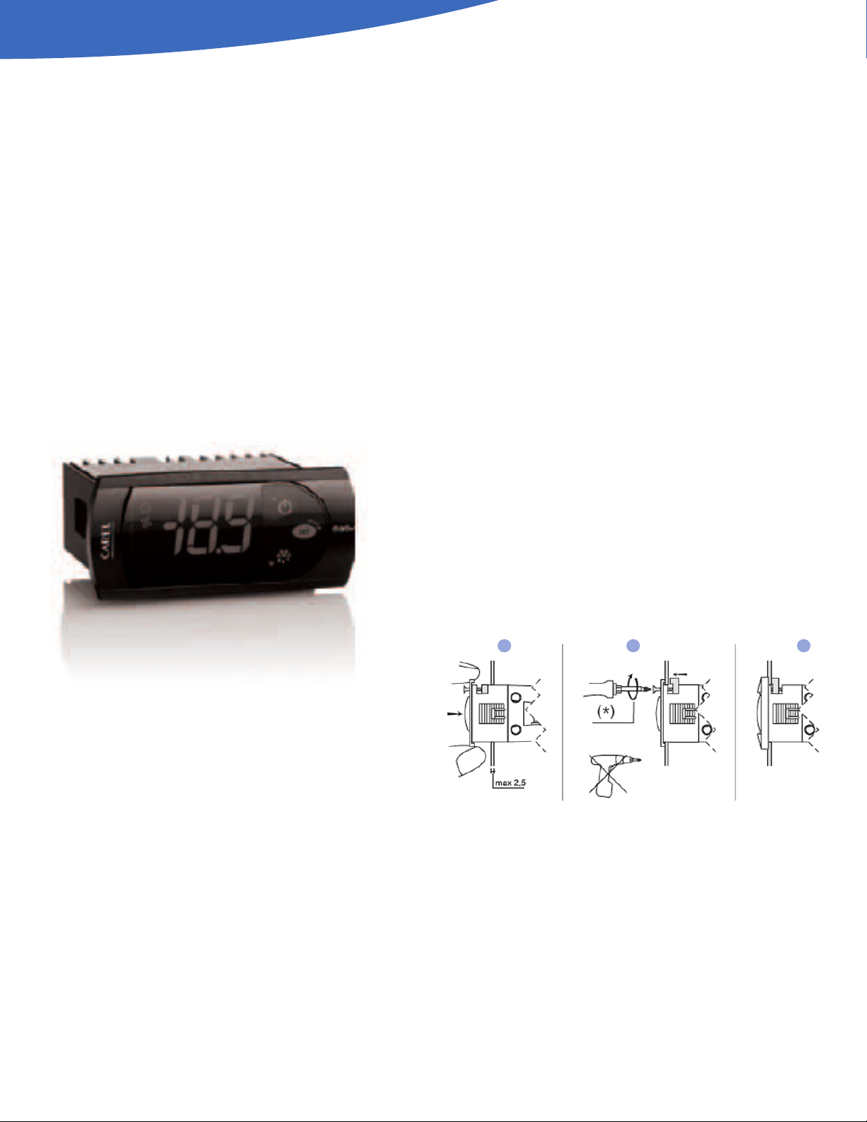
INSTALLATION AND REMOVAL
PANEL INSTALLATION FROM THE FRONT
USING SCREWS
■The thickness of the fastening panel must not
exceed 3 mm.
■Remove the front frame and make sure that the two
catches are in place (these must not protrude from
the outline of the drilling template). If necessary,
unscrew the two screws. Do not unscrew excessively,
the screws must not be detached from the front
panel (phase 1).
■Insert the instrument in the opening in the panel
and hold it in position by the centre of the front
panel (phase 1).
■Using the screwdriver, tighten the bottom screw 90°,
the catch must come out of its slot and click onto the
panel, then tighten until the front panel is secure.
Do not over-tighten, when the front panel is secured
blocks simply make another ½ turn to compress the
gasket; If the catch does not click onto the panel,
unscrew the screw, applying pressure at the same time
with the screwdriver so that the catch moves back. Do
not unscrew too much, the head of the screw must not
be raised from the surface of the front panel (phase 2).
■Repeat the same operation for the top screw (phase 2).
■Apply the front frame (phase 3).
DISMANTLING USING THE SCREWS FROM THE FRONT
■Unclip the front frame.
■Unscrew the bottom screw, at the moment the front
panel detaches from the panel keep pressure on the
screw and unscrew a further 90° to make the catch go
back into its slot.
■Repeat for the top screw.
■Remove the instrument from panel, keeping it
horizontal.
* Do not over-tighten the screws.
PHASE 1PHASE 2PHASE 3

11
But.
No. Function
Normal Operation
Start up
On O Flash
1 compressor on o call on
2 fan on o call on
3 defrost on o call on
4
auxiliary
output
(AUX)
output
active
output not
active – on
5clock
(RTC)
RTC
available,
enabled
(tEN=1) and
at least
one time
band has
been set)
RTC not
available or
not enabled
(tEN=0) or
no time
band set
on (if the
clock is
fitted)
6 alarm alarm in
progress
no alarm in
progress – on
7 digits
three digits with decimal point and range
-199 to 999. See parameters /4, /5, /6 for the
type of probe displayed, values in °C/°F and
decimal point
ELECTRICAL CONNECTIONS
WARNINGS:
The electrical connections must only be completed by a
qualified electrician.
A power supply other than the type specified may
seriously damage the system.
Separate as much as possible the probes and
digital input signal cables from the cables carrying
inductive loads and power cables to avoid possible
electromagnetic disturbance. Never lay power cables
(including the electrical cables) and probe signal cables
in the same conduits. Do not install the probe cables
in the immediate vicinity of power devices (contactors,
circuit breakers or similar).
Reduce the path of the probe and sensor cables as much
as possible, and avoid spiral paths that enclose power
devices. The probes must be connected using shielded
cables (minimum cross-section of each wire: 0.5 mm2).
Avoid direct contact with internal electronic components.
Connection errors (and connections other than those
indicated in this manual) may involve danger to the
safety of the users and cause faults on the instruments
and the components connected.
Fit the unit with all the electromechanical safety
devices required to guarantee correct operation and the
complete safety of the user.
CONTROLLER WIRING
DISPLAY
1
2
3
4
5
6
7
PJ EZ( C,Y )*

PRO3TOP MOUNT PACKAGED REFRIGERATION SYSTEM
12
But.
No.
Normal Operation
Start up
Pressing the
button alone
Pressing with
other buttons
1
more than 3
s: switch ON/
OFF
pressed
together with
3 activates/
deactivates
the continuous
cycle
–
2
- 1 s: displays/
sets the set
point
- more than
3 s: accesses
the parameter
setting
menu (enter
password 22)
- mutes the
audible alarm
(buzzer)
–
for 1 s
RESET
current EZY
set pressed
together
(2 and 3)
activate
parameter
reset
procedure
3
more than
3 s: activates/
deactivates
the defrost
pressed
together with
1 activates/
deactivates
the continuous
cycle
for 1 s
displays
firmware
version
Control Parameters
st set point
rd set point dierential
Defrost Parameters
d0 type of defrost
dl interval between two defrosts
dt end defrost temperature
dP maximum defrost duration
Alarm Parameters
Ad temperature alarm delay
AL low temperature alarm threshold/deviation
AH high temperature alarm threshold/deviation
KEYPADS PRELIMINARY CONFIGURATIONS
Once the electrical connections have been completed,
simply power-up the controller to make it operative.
Heatcraft recommends that you check the parameters
listed.
FUNCTIONS AVAILABLE FROM KEYPAD
ON AND OFF
Switching the instrument ON: press UP for more than 3 s
(when pressing the button, the display shows ON).
Switching the instrument OFF: press UP for more than 3 s.
The display shows the message “OFF”, alternating with the
temperature measured by the set probe.
In o status, the following functions are disabled
(if featured by the model):
■compressor control / duty setting / continuous cycle;
■defrost;
■fan control;
■alarms : ‘LO’, ‘HI’, ‘IA’, ‘cht’, ‘CHT’;
■door switch (A4= 7/8 );
■buzzer (when available)
While the following are enabled:
■temperature display, alternating with the message
“OFF”;
■parameter display and setting;
■alarms: “E0”, “E1”, “E2”;
■the internal timer relating to parameter ‘dI’ is updated.
If ‘dI’ expires in OFF status, a defrost is performed
when restarting;
■auxiliary relay management, only in the following
configurations:
¡ H1= = 1/2 (“E0” alarm only)
¡ H1= 3, A4= 6;
1
2
3

13
WARNING:
When first connected, easy is already on and ready to
be used. The instrument can be switched on from a
supervisor PC and via an external contact (setting
A4= 5). The latter has priority over the other modes.
SET POINT SETTING DESIRED TEMPERATURE VALUE
The easy and easy compact devices control the desired
temperature (set point) inside the cabinet or cold room
directly and dynamically.
To view and modify the set point:
■press SET for 1 s, the set value will start flashing.
■increase or decrease the value using UP or DOWN.
■press SET to confirm the new value.
MANUAL DEFROST
Press DOWN for more than 3 s (activated only if the
temperature conditions are right).
CONTINUOUS CYCLE
Press UP+DOWN for more than 3 s (activated only if the
temperature conditions are right).
The continuous cycle is used to maintain refrigeration
active in the cabinet or cold room, regardless of the
temperature inside the unit. This may be useful for rapidly
bringing the temperature below the set point value.
RAPID DISPLAY OF THE TEMPERATURE READ BY THE
OTHER PROBES
Press the DOWN button to scroll the temperatures read
by the probes. Each time the DOWN button is pressed,
the display will show the name of the probe Pr1, Pr2 or Pr3
(only on the models with 3 inputs and with multifunction
input configured as a probe) and after 1 s the temperature
measured by the selected probe will be displayed.
To display the other probes, press DOWN again.
To return to the normal display, wait 3 s without pressing
any buttons (exit by timeout).
TEMPERATURE DISPLAY
The temperature displayed, the unit of measure and the
decimal resolution can be set according to the following
parameters: /4, /5 and /6.
/4 : SELECT PROBE DISPLAYED
Used to choose whether to display the temperature read
by the control probe (Probe 1), Probe 2 or the status of the
multifunction input (analogue or digital).
Parameter /4 selects the probe shown on the display, all
the other display and control modes remain unchanged.
IMPORTANT: the easy compact models can display up to
2 probes.
/5: SELECT °C/°F
Defines the unit of measure used for temperature control.
/5=0 to work in °C
/5=1 to work in °F.
WARNING:
When changing from one unit of measure to the other, all
the values of the temperature parameters are modified
to the new unit of measure.
The max and min limits of the absolute temperature
parameters are the same for both °C that °F. The range of
temperatures allowed is therefore dierent between °C
and °F:
/6: DISABLE DECIMAL POINT
Used to enable or disable the temperature display with the
resolution to the tenths of a degree between -20 and + 20
(easy) or -10 and +10 (easy compact).
/6= 0 temperature displayed to the tenth of a degree;
/6=1 temperature displayed without the tenths of a degree.
NOTE: the decimal point is only disabled in relation to the
reading shown on the display (the calculations performed
by the controller remain unchanged).
TEMPERATURE CONTROL
The following parameters are used to control the
temperature: St, r1, r2, r3, r4 and rd.
ST: SET POINT, R1 MINIMUM VALUE AND R2 MAXIMUM
VALUE OF THE SET POINT
Parameter St determines the desired temperature to be
maintained inside the cabinet or cold room (set point).
Parameters r1 (minimum value) and r2 (maximum) set the
range of temperatures for setting the set point.
NOTE: the set point can be set by pressing the SET button
(see par. “Setting the set point (desired temperature
value)” page 11).
R3: SELECT DIRECT/REVERSE OPERATION
Defines the operating mode of the device:
■r3=0: direct with defrost. Used to request the
activation of the compressor when the temperature
measured by probe 1 rises above the set point. This
mode also includes defrost.
■r3=1: direct without defrost.
■r3=2: reverse without defrost. Used to request the
activation of the compressor when the temperature
measured by probe 1 falls below the set point. This
mode does NOT include defrost.

PRO3TOP MOUNT PACKAGED REFRIGERATION SYSTEM
14
RAPID PARAMETER SET SELECTION EZY
The easy controller features the EZY parameter which
is used to quickly choose a list of parameters, with
corresponding values, for the control of the refrigeration
system.
TABLE OF ALARMS AND SIGNALS
When an alarm is activated, the display shows the
corresponding message that flashes alternating with the
temperature; if fitter and enabled, the buzzer and the alarm
relay are also activated.
All the alarms have automatic reset (that is, they stop when
the causes are no longer present), except for alarm ‘CHt’
which has manual reset (instrument on/o using the UP
button or by disconnecting the power supply).
NOTE:
■To restore the selected rapid parameter set at any
time, turn the controller o and on again, while holding
SET. The display shows “CE” to indicate that the
selected rapid set (EZY= 1, 2, 3) has again over written
the operating parameters, thus restoring the original
set of parameters.
■To restore all the parameters and return to the original
default values (factory settings), turn the controller o
and on again while holding DOWN and SET, until the
display shows “CF”. Use this procedure with extreme
car, as it may compromise the fundamental control
settings.
■EZY= 0 brings no change
Pressing the SET button mutes the buzzer, while the code
displayed and the alarm relay only go o when the causes
of the alarm have been resolved. The alarm codes are
shown in the able below:
Alarm
Code
Buzzer and
Alarm Relay LED Alarm Description Reset Enable Alarm
parameters involved
E0 active ON probe 1 error= control automatic –
E1 not active ON probe 2 error= defrost automatic d0= 0 / 1 / 4, F0= 1
E2 not active ON probe 3 error= condenser/ product automatic [A4=10]
IA active ON external alarm automatic [A4 = 1] [+A7]
dOr active ON open door alarm automatic [A4 = 7/8][+A7]
LO active ON low temperature alarm automatic [AL] [Ad]
HI active ON high temperature alarm automatic [AH] [Ad]
EE not active ON unit parameter error not possible –
EF not active ON operating parameter error manual –
Ed not active ON defrost ended by timeout on first defrost ended correctly [dP] [dt] [d4] [A8]
dF not active OFF defrost running automatic [d6=0]
cht not active ON dirty condenser pre-alarm automatic [A4=10]
CHt active ON dirty condenser alarm manual [A4=10]
EtC not active ON clock alarm by setting the time if bands active

15
DESCRIPTION OF THE MAIN SIGNALS AND ALARMS
LED FLASHING
The activation of the corresponding function is delayed by
a timer, awaiting an external signal or disabled by another
procedure that is already in progress. e.g. if is a continuous
cycle in progress and a defrost is called, the latter will
remain pending until the end of the continuous cycle, and
the corresponding LED (defrost) will flash.
E0 STEADY OR FLASHING
Control probe error:
■Probe not working: the probe signal is interrupted or
short-circuited;
■Probe not compatible with the instrument;
The alarm signal E0 is steady if it is the only active alarm
(the temperature value is not displayed), while it fl ashes if
other alarms are active or the second probe is displayed.
E1 FLASHING
Evaporator probe or food conservation probe error:
■Probe not working, the probe signal is interrupted or
short-circuited;
■Probe not compatible with the instrument;
E2 FLASHING
Condenser probe or food conservation probe error:
■Probe not working, the probe signal is interrupted or
short-circuited;
■Probe not compatible with the instrument;
IA FLASHING
Immediate or delayed alarm from multifunction
digital input:
■Check the multifunction input and parameters A4
and A7.
LO FLASHING
Low temperature alarm. The probe has measured a
temperature lower than the set point by a value that
exceeds parameter AL:
■Check parameters AL, Ad and A0.
The alarm is automatically reset when the temperature
returns within the set limits (see parameter AL).
HI FLASHING
High temperature alarm. The probe has measured a
temperature higher than the set point by a value that
exceeds parameter AH.
■Check parameters AH, Ad and A0.
The alarm is automatically reset when the temperature
returns within the set limits (see parameter AH).
EE DISPLAYED DURING OPERATION OR ON POWERUP
Unit parameter reading error. See Data errors.
EF DISPLAYED DURING OPERATION OR ON POWERUP
Operating parameter reading error. See Data errors.
ED FLASHING
The last defrost ended after exceeding the maximum
duration rather than when reaching the end defrost
set point.
■Check parameters dt, dP and d4;
■Check the eciency of the defrost.
The message disappears when the next defrost ends
correctly.
DF FLASHING
Defrost running:
■This is not an alarm signal, but rather a message that
the instrument is running a defrost. Only shown if
d6= 0.
CHT FLASHING
Dirty condenser alarm:
■Check parameters A4, Ac, AE and Acd.
ETC FLASHING
Internal clock error.
DATA ERROR
In certain operating conditions, the instrument may detect
errors in the data saved. These errors may compromise
the correct operation of the instrument. If the
microprocessor detects a data saving error, the display
shows the message “EE”.
If the fault persists, the controller needs to be replaced.
If, on the other hand, the message disappears, it can
continue to be used. When “EE” error occurs frequently
and/or remains for some time, the controller should be
checked, as the original precision may not be guaranteed.

PRO3TOP MOUNT PACKAGED REFRIGERATION SYSTEM
16
MODIFYING THE PARAMETERS
PARAMETER NAVIGATION
The operating parameters, modifiable using the keypad,
are divided into two types: frequent (type F) and
configuration (type C). Access to the latter is protected
by password (default= 22) to prevent accidental or
unauthorized modifications.
ACCESSING THE TYPE F PARAMETERS:
■Press the SET button for more than 3 s (if there are
active alarms, mute the buzzer), the display shows the
parameter code ‘PS’ (password).
■Use the UP and DOWN buttons to scroll the
parameters. The LED corresponding to the category of
parameters will be on.
■Press SET to display the value associated with the
parameter increase or decrease the value using the
UP or DOWN button respectively.
■Press SET to temporarily save the new value and
display the parameter again.
■Repeat the procedure for any other parameters that
need to be modified.
■Press the SET button for more than 3 s to permanently
save the parameters and exit the parameter setting
procedure.
ACCESSING THE TYPE C PARAMETERS:
■Press the SET button for more than 3 s (if there are
active alarms, mute the buzzer), the display shows the
parameter code “PS” (password).
■Press the SET button to access the password setting.
■Use the UP and DOWN buttons to scroll the numbers
until displaying “22” (password to access the
parameters).
■Press the SET button to confirm the password.
■Use the UP and DOWN buttons to scroll the
parameters. The LED corresponding to the category of
parameters will be on (see Table below).
■Press SET to display the value associated with the
parameter increase or decrease the value using the
UP or DOWN button respectively.
■Press SET to temporarily save the new value and
display the parameter again.
■Repeat the procedure for any other parameters that
need to be modified.
■Press the SET button for more than 3 s to permanently
save the parameters and exit the parameter setting
procedure.
WARNINGS:
If no button is pressed for 60 s, all the changes made to
the parameters, temporarily saved in the RAM, will be
canceled and the previous settings restored.
The Day, Hr, Min parameters are not restored, as these
are saved instantly when entered.
If power is disconnected from the instrument before
saving the settings (pressing the SET button for 3 s), all
the changes made to the parameters and temporarily
saved will be lost.
SETTING THE DEFAULT PARAMETERS
WARNINGS:
Running this procedure overwrites any custom
parameter settings.
To reset the default parameters:
■Disconnect power from the instrument.
■Reconnect power while holding the SET and DOWN
buttons.
■The display will show the message “CF”.
■After a few seconds the instrument starts operating
with the default configuration. Any dierent parameter
settings will need to be updated.

17
Problem Cause Checks
the compressor does not start
(signaled by the compressor LED flashing)
• compressor delay set defrost post
• dripping in progress parameters c0, c1 and c2 and dd
the temperature is over the set limits but there
is no alarm message and the buzzer, if fitted,
does not sound
alarm delay set parameters Ad, c6, d8
alarm IA is signaled (multifunction input)
without actually being active
the multifunction input generates an
alarm when the contact opens
connection of the input and whether
this is closed in normal operation
the alarm connected to the multifunction
input is not detected
alarm delay set or parameter
programming error
1. if A4=1
2. the status of digital input A7
the defrost is not activated
defrost duration too short (dP)
interval between defrosts dI=0:
in this case the defrost is not activated
parameters dP and dI
the end defrost temperature is too low or
the evaporator temperature is too high parameters dt and d/ (defrost probe)
the manual defrost is not activated and the
defrost LED flashes compressor protection times set parameter d9 (select d9=1)
the high temperature alarm is shown
after a defrost
the alarm delay after defrost is too
short or the alarm threshold is too low parameters d8 and AH
the display remains frozen even
after the defrost
the ambient temperature has not yet
reached the set point or alternatively
the time d8 has not elapsed
wait or reduce d8
after modifying a parameter the controller
continues working with the old values
the instrument has not updated the old
value or alternatively the parameter setting
procedure has not been ended correctly
by pressing the SET button for 3 s
turn the instrument o and on again
or alternatively reprogram the
parameters correctly
the evaporator fan does not start 1
1. a compressor and fan start delay has
been set
2. if F0=1 (fan managed by fan controller)
• the evaporator is “hot”: the evaporator
temperature can be read by selecting
parameter /d
• dripping in progress
• F1 (evaporator fan control set point)
too low
• post-dripping delay set
3. if F0=0
• F2=1 and the compressor is o
• dripping in progress
• post-dripping in progress
1. parameter c0
2. parameters F0, F1, Fd, dd and d/
3. parameters F0, F2, dd and Fd
TROUBLESHOOTING
The following table shows a number of situations that may occur on the various models.
The most frequent causes and corresponding checks are described:

PRO3TOP MOUNT PACKAGED REFRIGERATION SYSTEM
18
DEVICE SETUP
Parameter Description Min Max Default
St Set point -30 30 -10
r1 Minimum set point value -50 303 -30
r2 Maximum set point value -30 150 30
c2 Minimum compressor o time 0 100 4
do Type of Defrost 0 4 0
dI Interval between defrost 0 199 6
dt End defrost temperature set point -50 127 65
dP Maximum defrost duration ALARM_ED 1 199 60
d4 Defrost on power-up 0 1 1
dd Dripping time 0 15 2
F0 Enable evaporator fan control 0 1 0
F2 Stop evaporator fan if compressor o 0 1 0
F3 Evaporator fan status during defrost 0 1 1
Fd Post-dripping time 0 15 2
Parameter Description Min Max Default
St Set point 0 50 34
r1 Minimum set point value -50 50 0
r2 Maximum set point value 0 150 50
c2 Minimum compressor o time 0 100 4
do Type of Defrost 0 4 0
dI Interval between defrost 0 199 6
dt End defrost temperature set point -50 127 65
dP Maximum defrost duration ALARM_ED 1 199 60
d4 Defrost on power-up 0 1 1
dd Dripping time 0 15 2
F0 Enable evaporator fan control 0 1 0
F2 Stop evaporator fan if compressor o 0 1 0
F3 Evaporator fan status during defrost 0 1 1
Fd Post-dripping time 0 15 0
St Set point 0 50 38
r1 Minimum set point value -50 50 0
r2 Maximum set point value 0 150 50
c2 Minimum compressor o time 0 100 4
do Type of Defrost 0 4 2
dI Interval between defrost 0 199 6
dt End defrost temperature set point -50 127 40
dP Maximum defrost duration ALARM_ED 1 199 40
d4 Defrost on power-up 0 1 0
dd Dripping time 0 15 0
F0 Enable evaporator fan control 0 1 0
F2 Stop evaporator fan if compressor o 0 1 0
F3 Evaporator fan status during defrost 0 1 0
Fd Post-dripping time 0 15 0
Set o
Set o
Set o
Set 1
Set 1
Set 1
Set 2
Set 2
Set 2
Set 3
Set 3
Set 3
Set 4
Set 4
Set 4
Set 1 - Low Temperature Models - Electric Defrost w/ -10° F Set Point
Set 2 - Medium Temperature Models - Electric Defrost w/ 34° F Set Point
Set 3 - Medium Temperature Models - Air Defrost w/ 38° F Set Point

19
Table 5: PRO
3
System Troubleshooting Chart
PROBLEM POSSIBLE CAUSES POSSIBLE CORRECTIVE STEPS
Compressor will not run
1. Main switch open. 1. Close switch.
2. Fuse blown. 2
Check electrical circuits and motor winding for shorts or grounds.
Investigate for possible overloading. Replace fuse after fault is corrected.
3. Thermal overloads tripped. 3. Overloads are automatically reset. Check unit closely when unit
comes back on line.
4. Defective contactor or coil. 4. Repair or replace.
5. System shut down by safety devices. 5. Determine type and cause of shutdown and correct it
before resetting safety switch.
6. No cooling required. 6. None. Wait until calls for cooling.
7. Motor electrical trouble. 7. Check motor for open windings, short circuit or burn out.
8. Loose wiring. 8. Check all wire junctions. Tighten all terminal screws.
Compressor noisy or vibrating
1. Flooding of refrigerant into crankcase. 1. Check setting of expansion valves.
2. Worn compressor. 2. Replace.
High discharge pressure
1. Non-condensables in system. 1. Remove the non-condensables.
2. Fan not running. 2. Check electrical circuit. Replace if motor fails.
3. Dirty condenser coil. 3. Clean.
4. System overcharged with refrigerant. 4. Reclaim refrigerant and recharge proper amount.
Low discharge pressure
1. Insucient refrigerant in system. 1. Check for leaks. Repair and add charge.
2. Low suction pressure. 2. See corrective steps for low suction pressure.
High suction pressure
1. Excessive load. 1. Reduce load or add additional equipment.
2. Expansion valve overfeeding. 2. Check remote bulb. Regulate superheat.
Low suction pressure
1. Lack of refrigerant. 1. Check for leaks. Repair and add charge
2. Evaporator dirty or iced. 2. Clean.
3. Expansion valve malfunctioning. 3. Check and reset for proper superheat.
4. Condensing temperature too low. 4. Check ambient temperature 50°F to 100°F.
Compressor thermal protector
switch open
1. Operating beyond design conditions. 1. Add equipment so that conditions are within allowable limits.
2. Dirty condenser coil. 2. Clean coil.
3. Overcharged system. 3. Reduce charge
Fan(s) will not operate
1. Main switch open. 1. Close switch.
2. Blown fuses. 2. Replace fuses. Check for short circuits or overload conditions.
3. Defective motor. 3. Replace motor.
4. Defective defrost control. 4. Replace defective component.
5. Unit in defrost cycle. 5. Wait for completion of cycle.
6. Coil does not get cold enough to reset thermostat. 6. Adjust fan delay setting of control.
Room temperature too high
1. Control cut out set too high. 1. Adjust control.
2. Superheat too high. 2. Adjust thermal expansion valve.
3. System low on refrigerant. 3. Add refrigerant.
4. Coil iced-up. 4. Manually defrost coil. Check defrost controls for malfunction.
Ice accumulating on ceiling around
evaporator and/or on fan guards’
venturi or blades
1. Defrost duration is too long. 1. Adjust defrost termination temperature on control.
2. Fan delay not delaying fans after defrost period. 2. Adjust fan delay setting or replace bad sensor.
3. Defective defrost control or sensor. 3. Replace defective control or sensor.
4. Too many defrosts. 4. Adjust number of defrosts.
Coil not clearing of frost during
defrost cycle.
1. Coil temperature not getting above freezing point during defrost. 1. Check heater operation.
2. Not enough defrost cycles per day. 2. Adjust control for more defrost cycles.
3. Defrost cycle too short. 3. Adjust defrost control, defrost duration setting.
4. Defective defrost control or sensor. 4. Replace defective component.
Ice accumulating in drain pan
1. Defective heater. 1. Replace heater.
2. Unit not installed properly (out of level). 2. Check and adjust if necessary.
3. Drain line plugged. 3. Clean drain line.
4. Defective control. 4. Replace defective component.

PRO3TOP MOUNT PACKAGED REFRIGERATION SYSTEM
20
Model
Cabinet, Voltage/Phase
P1, 115/1 P2, 115/1 P2, 230/1 P3, 230/1 P3, 230/3
Motor - Condenser 25308501 25308501 25322404 25322404 25322404
Motor - Evaporator 25319301 25329001 25329101 25329101 25329101
Fan blade - Condenser 22900601 5110E 22901601 22901601 22901601
Fan blade - Evaporator 23100501 22901901 22901901 22901901 22901901
Motor Mount - Condenser 23101101 23103301 23106101 23106101 23106101
Motor Mount - Evaporator 23101401 23103301 23103301 23103301 23103301
Contactor 2252303 2252303 R034915200 R034915200 2259996
Temperature Controller 21301101 21301101 21301001 21301001 21301001
Room Temp Sensor 28913702 28913702 28913702 28913702 28913702
Defrost Temp Sensor 28913701 28913701 28913701 28913701 28913701
Heater Limit Thermostat 5708L 5708L 5708L 5708L 5708L
Defrost Heaters 24751901 24712101 4312F 4313F 4313F
Fan Pressure Control N/A N/A 28917302 28917302 28917302
Fan Temp Control N/A N/A N/A 5521R 5521R
Drain Line Heater N/A N/A 24753401 24753401 24753401
Drain Line Heater T’stat N/A N/A 28917401 28917401 28917401
Weatherhood N/A N/A 59332801 50087601 50087601
REPLACEMENT PARTS
www.interlinkparts.com
800.686.7278
Right source. Right parts. Right now.
InterLink™ is your link to a complete line of dependable and certified
commercial refrigeration parts, accessories and innovative electronic controls
for all Bohn equipment. At InterLink, we provide our wholesalers with a
comprehensive selection of product solutions and innovative technologies
for the installed customer base. And every product is built to ensure the same
high performance standards with which all Heatcraft Refrigeration Products
brands are built — backed by a dedicated team to serve every customer need,
delivering at the best lead times in the industry.
Dependable. Versatile. Courteous.
Finally, one simple source for all your replacement needs from a name you
can trust.
Table of contents
Other Heatcraft Accessories manuals


