Heateflex AQUARIUS Series User manual

World Leaders in Ultra-Pure Heating
www.heateflex.com
405 E. Santa Clara St., Arcadia, CA 91006-7218
O
: (626) 599-8566
F
: (626) 599-9567
AQUARIUS
SERIES
DI WATER HEATING SYSTEM
INSTRUCTION MANUAL

World Leaders in Ultra-Pure Heating
www.heateflex.com
405 E. Santa Clara St., Arcadia, CA 91006-7218
O
: (626) 599-8566
F
: (626) 599-9567
INDEX
Section I – INSTRUCTION MANUAL
Table of Contents
Shipping and Unpackaging Procedure
Receiving Inspection Procedure
Introduction
Factory Performance Test
Basic Safety Precautions
Sequence of Installation Instructions
Suggested Operational Inspection
Auto Purge / Purge
Recirculation System and Pump Air Cooling System
Trouble Shooting Guide
Environmental Specifications
Aquarius D.I. Water Heating System Options
Warranty
Declaration of Conformity (Optional)
Section II – QUALITY CONTROL & EQUIPMENT SPECIFICATIONS
Quality Control Documentation
Equipment Specifications
Suggested Spare Parts List
Section III – DRAWINGS
Facility Diagram
Mechanical Layout
Plumbing Diagram
Electrical Component Layout
Electrical Schematic Diagram(s)
Section IV – PF2000 CONTROLLER MANUAL

2
World Leaders in Ultra-Pure Heating
www.heateflex.com
405 E. Santa Clara St., Arcadia, CA 91006-7218
O
: (626) 599-8566
F
: (626) 599-9567
SECTION I
TABLE OF CONTENTS
Shipping and Unpackaging Procedures ....................................................................... 4
Receiving Inspection Procedure ................................................................................... 6
Introduction .................................................................................................................. 7
Factory Performance Test ............................................................................................ 9
Basic Safety Precautions ............................................................................................. 12
Pre-Installation Preparation .......................................................................................... 15
Installation Instructions ................................................................................................. 16
System Shut Down Procedure ..................................................................................... 19
Suggested Operational Inspection ............................................................................... 20
Decontamination and Decommissioning ...................................................................... 21
Aquarius with Optional Auto Purge Feature ............................................................... 22
Aquarius with Optional Recirculation Feature............................................................. 23
Aquarius Recirculation Pump Air Cooling System ........................................... 26
Trouble Shooting for the Aquarius DI Water Heating System ...................................... 30
Environmental Specifications ....................................................................................... 34
Aquarius Available Options ........................................................................................ 36
Aquarius Auto Purge (Option) .......................................................................... 36
Resistivity Sensor (Option) ................................................................................ 37
Water Leak Sensor with Auto Shut OFF (Option) .............................................. 38
Analog Interface Package (Option) .................................................................... 39
Discrete Interface Package (Option) .................................................................. 39
Dry contact Interface Package (Option) ............................................................. 40
Communications ................................................................................................ 41
Aquarius Cable Assemblies (Option) ............................................................... 41
Secondary Process Temperature Set Point (Option) ......................................... 41
Aquarius Recirculation................................................................................................ 41
Aquarius Options ........................................................................................................ 42
Additional System Options/Configurations ................................................................... 43
Heateflex Corporation’s Material Warranty ................................................................... 44

3
World Leaders in Ultra-Pure Heating
www.heateflex.com
405 E. Santa Clara St., Arcadia, CA 91006-7218
O
: (626) 599-8566
F
: (626) 599-9567
Declaration of Conformity ............................................................................................. 46
Manual Revisions ......................................................................................................... 48

4
World Leaders in Ultra-Pure Heating
www.heateflex.com
405 E. Santa Clara St., Arcadia, CA 91006-7218
O
: (626) 599-8566
F
: (626) 599-9567
Shipping and Unpackaging Procedures
The proper shipping procedure for the Aquarius Deionized (D.I.) Water Heating
Systems includes shipping the unit in a horizontal position as shown and described
in the illustration below.
The Aquarius D.I. Water Heating Systems are factory tested to ensure that you
receive an operational unit. The Aquarius D.I. Water Heating Systems are
packaged and shipped in the horizontal position along its side. The unit is wrapped
in bubble pack, plastic wrapped and then placed onto a pallet with a 2 1/2” thick
impact absorbing foam pad. The unit is strapped down to the pallet then covered
with a corrugated box or crating material, taped and then re-strapped.
Once the Aquarius D.I. Water Heating System has thoroughly been inspected for
damage that may have occurred during shipping (if any damage has occurred refer
to the Receiving Inspection Procedure of this Instruction Manual), the unit will need
to be moved from its horizontal shipping position to its normal functional vertical
position. Remove any packaging materials such as the box or crate, Styrofoam
block, straps, etc. Once the unit is free and ready to be moved, verify that the plinth
base and/or eyebolts are in position. The unit can be transported using either the
supplied eyebolts or by fork-lift truck. Using the eyebolts, systematically distribute
the load using the following parameters. For cable angle 45°, use a max load of
1080 pounds. For cable angle 60°, use a max load of 1440 pounds. For cable angle
90°, use a max load of 3060 pounds. Using a fork-lift truck, ensure that the unit is
under 3150 pounds. Carefully lift the top part of the unit (opposite of the plinth base)
and tilt the unit from its horizontal shipping position to its operational vertical position.
Remove the stretch and bubble wrap.

5
World Leaders in Ultra-Pure Heating
www.heateflex.com
405 E. Santa Clara St., Arcadia, CA 91006-7218
O
: (626) 599-8566
F
: (626) 599-9567
All Aquarius D.I. Water Heating Systems are equipped with a plinth base to
maneuver the Aquarius D.I. Water Heating System vertically, in its functional
orientation.

6
World Leaders in Ultra-Pure Heating
www.heateflex.com
405 E. Santa Clara St., Arcadia, CA 91006-7218
O
: (626) 599-8566
F
: (626) 599-9567
Receiving Inspection Procedure
This shipment was carefully inspected, checked, and properly packaged at Heateflex
Corporation and delivered to the shipping carrier in good condition. We fully expect
your merchandise to arrive in your hands in excellent operational condition.
ALL PRODUCTS ARE SHIPPED F.O.B. FACTORY; THEREFORE, WHEN IT IS
DELIVERED TO THE SHIPPING CARRIER, IT BECOMES YOUR PROPERTY.
THUS, IT IS IMPORTANT THAT YOU TAKE NOTE OF ANY DAMAGE, WHETHER
OBVIOUS OR HIDDEN. REPORT THIS INFORMATION TO THE
TRANSPORTATION COMPANY WITHIN 5 DAYS OF RECEIPT OF THE SHIPMENT
AT YOUR PREMISES TO AVOID FORFEITING CLAIMS FOR DAMAGE.
WHAT TO DO IF SHIPMENT IS DAMAGED:
Leave the items, packing material and carton “as is”. Notify your carrier’s
local office and ask for immediate inspection of the carton and contents.
After the shipping carrier has made inspection, and you have received
acknowledgment in writing as to the damage, please contact our Customer
Service Department for return authorization at:
(626) 599-8566
If writing for return authorization, please indicate your purchase order
number.
We will either repair or replace the merchandise depending upon the extent
of the damage.
It is your responsibility to follow the above instructions, or the shipping
carrier will not honor any claims for damage. If there are any shortages or
questions regarding this shipment, please notify us within 10 days.

7
World Leaders in Ultra-Pure Heating
www.heateflex.com
405 E. Santa Clara St., Arcadia, CA 91006-7218
O
: (626) 599-8566
F
: (626) 599-9567
Introduction
While the official language of the “Original Instructions” is in English, any interpretation
of this Instruction Manual in other Community languages will be discussed by the
manufacturer (Heateflex Corporation) and the customer on an as required basis.
Your new Aquarius D.I. Water Heating System is engineered to offer a safe, reliable,
and effective solution to de-ionized heating needs by providing at temperature ultra-
pure D.I. water. These systems are designed to reduce water usage as well as
maintain high purity requirements. This has been achieved using our patented
HEATEFLEX heaters and Power-to-Flow Control system.
Heateflex’s patented Power-to-Flow Control system eliminates undesirable
overshoots or drops in temperature, which are commonly the result of inadequate PID
temperature controllers. The Aquarius D.I. Water Heating Systems are designed to
maintain accurate user-specified temperature even with process flow rate variations
and during recirculation (Systems equipped the recirculation option only). The Power-
to-Flow Control system compensates for changes in the process flow rate by
measuring the flow rate of the fluid as it enters the heaters, measuring the temperature
at various stages in the heating process, and adjusting the proportion of power applied
to each heating zone based on those measurements. This integrated control method
is advancement to previous methods of temperature control that reacts quickly and
robustly to any variations in flow, providing a steady supply of ultra-pure D.I. water at
a stable temperature.
High purity is maintained throughout the heating process due to the use of PVDF, FEP,
and PFA wetted surfaces. The Aquarius D.I. Water Heating Systems are equipped
with many safeties and components such as thermocouples, a liquid level sensor, a
flow sensor, a pressure transducer, high limit sensors, and thermal cut-off sensors to
protect the heater modules from unnecessary damage due to overheating. All
Aquarius D.I. Water Heating Systems come standard with a pressure by-pass protect
against over pressurization of the unit. Shorted SCR sensing has been incorporated
in the Aquarius for added heater protection. A Safety Relay, Safety PLC and GFCI
are standard on the Aquarius which provides added protection to the unit and for
operators. To monitor the purity level of the exiting heated D.I. water, a resistivity
sensor is available as an option on the Aquarius D.I. Water Heating Systems. The
Power-to-Flow Control system also incorporates the use of a visual touch screen user
interface which is straightforward and easy to operate with only a few adjustments
needed after initial settings are entered.
Our Aquarius systems satisfy all CE and SEMI'S Safety Standards and they are
equipped with safety devices to protect the users as well as the products that they are
processing. These safety devices include

8
World Leaders in Ultra-Pure Heating
www.heateflex.com
405 E. Santa Clara St., Arcadia, CA 91006-7218
O
: (626) 599-8566
F
: (626) 599-9567
1) Emergency Off (EMO) button - An Emergency Off (EMO) button located on the
front of the unit (and remotely if option is selected) is utilized by the user in the event
of an emergency condition to shut power to the unit (and other devices if option is
selected). It is a SEMI S2 compliant device with a direct opening action mechanism,
and safe break action.
2) Door Interlock Switch - A door interlock switch mounted to the front cabinet door
is used to indicate if the door is open or closed. If the front door is open, the power
will be cut to the unit. This safety device features force guided contacts and a
tamper resistant mechanism.
3) Safety Relay – The Safety Relay monitors both the Emergency Off button and the
Door Interlock Switch. The Safety Relay incorporates redundant relays in
conjunction with the emergency off button switch and the safety open-door interlock
to achieve safety category 3. The Safety Relay determines whether or not to
provide power to the unit.
4) Ground Fault Circuit Interrupter (GFCI) – The Ground Fault Circuit Interrupter
(GFCI) monitors the heater amperage and any circuits containing 120 volts or more
if a suspicious current leak is detected in the circuitry.
5) Thermal Cut-Off Sensor – The thermal cut-off sensor is a thermal sensor which
opens once it’s breaking temperature is exceeded. It is used to shut down the
heater when a runaway heating condition occurs.
6) Safety PLC (Programmable Logic Controller) - Safety PLC monitors the high
limit thermocouples, the GFCI and Thermal Cut-off Sensor status using redundant
force guided relays, and controls the Heater Master Relay (which controls the
heater contactor) and the Heater Safety Relay (which controls the SCR output
signals to the heater).
7) Water Leak Deluxe (Optional) – The water leak deluxe option consists of
monitoring for system leaks via water leak sensor and isolation valves which shut
off the incoming process fluid and the heaters as well. This option allows the user
to isolate and reduce a pressurized system to a zero-energy state prior to
maintenance or service work. The system uses two pneumatically or manually
operated 2/2-way diaphragm valves to isolate the system. The valves are
located at the input and output. (Optional).
8) Lockout/Tagout (Optional) - Lockout/Tagout is optional for the Aquarius D.I.
Water Heating System. This provides a fusible disconnect switch on the unit
and conforms to SEMI S2-0715 to isolate the unit electrically for maintenance
and service work. The handle is lockable. If the lockout/tagout option is not
included, the main disconnect is customer supplied. (Optional)
We are confident in the quality and reliability of our products and offer technical support if
needed.

9
World Leaders in Ultra-Pure Heating
www.heateflex.com
405 E. Santa Clara St., Arcadia, CA 91006-7218
O
: (626) 599-8566
F
: (626) 599-9567
Factory Performance Test
The following tests are performed on all Aquarius D.I. Water Heating Systems after
assembly and before shipping. The units are tested with D.I. water supplied to the unit
and discharged to drain.
1. A high potentiometer test procedure is performed on the heaters used in the
Aquarius D.I. Water Heating System. The test procedure includes a leak,
thermocouple, and resistance test. For detail, reference document number 1201.
2. Voltage, Flow, and Pressure readings on the controller are calibrated as follows:
a. The incoming voltage is measured on the input side of the contactor by a
voltmeter. If the measured voltage reading does not match the voltmeter
reading on the screen, the voltage value is adjusted accordingly by
adjusting the voltage calibration parameter which is located on the System
Calibration screen of the System Set Up Menu.
b. An external flow meter is plumbed in-line with the D.I. water heater. The
flow reading on the touch screen should match the reading indicated on
the external flow sensor. If an adjustment is required the flow meter value
is adjusted accordingly by adjusting the flow calibration parameter which is
located on the System Calibration screen of the System Set Up Menu.
c. An external pressure meter is plumbed in-line with the D.I. water heater.
The pressure reading on the touch screen should match the reading
indicated on the external sensor. If an adjustment is required the pressure
value is adjusted accordingly by adjusting the pressure calibration
parameter which is located on the System Calibration screen of the
System Set Up Menu.
For more detailed information on the Aquarius control system and operation
screens please refer to the PF2000 Controller manual.
3. The Aquarius control system is monitored and controlled by a PLC
(Programmable Logic Controller) and related hardware of the Aquarius and
checked for functionality.
a. The inputs and outputs of the Safety PLC are checked and verified.
b. All components and sensors are checked and tested.
c. Control system functionality are checked and tested.
4. The Aquarius D.I. Water Heating Systems are tested to operate with the
“Process Temperature Set Point” parameter set to the maximum temperature
possible according to the equation below. This test will insure that all heater
modules are operating and full heater power is available.
a. The proper flow rate is first calculated using the following formula:

10
World Leaders in Ultra-Pure Heating
www.heateflex.com
405 E. Santa Clara St., Arcadia, CA 91006-7218
O
: (626) 599-8566
F
: (626) 599-9567
C)( D.I. INPUT TEMP C95
3.79KW
GPM
b. The calculated flow rate is introduced to the D.I. water heater and the unit
is turned on. The D.I. water heater is allowed to reach the process
temperature set point.
c. At 95°C, the unit may trigger the High Temperature Alarm. The High
Temperature Alarm indicates that adjustments are possibly required.
Make adjustments as indicated on the TROUBLE-SHOOTING GUIDE.
5. The Aquarius D.I. Water Heating Systems are tested at “Process
Temperature Set Point” parameter set below the maximum temperature
possible and 1 GPM D.I. water flow. This will test the performance of the
controller.
a. The unit is allowed to operate with the controller “Process Temperature
Set Point” set to a value below the maximum temperature possible and
flow set to 1 GPM.
b. If the temperature is not stable, confirm that the controller’s parameters
are set to factory settings shown in the user’s manual. If further controller
tuning is required, see the TROUBLESHOOTING GUIDE.
6. The Aquarius D.I. Water Heating Systems are tested for the correct operation
of the following safety interlocks or alarms:
a. Components: The components of the Aquarius is thoroughly checked
for functionality, which includes the Safety Relay(CON2), Door Interlock,
EMO (Emergency Off), SCR (Silicon Controlled Rectifier), Safety PLC,
High Limit T/C Monitoring, Liquid Level, Thermal Cut-Off Sensor, Leak
Sensors (Optional), GFCI, and Current Transformer.
b. Flow Sensor: The system flow rate is indicated by the FLOW RATE value
readout on the System Status screen. Modify the current “Low Flow
Alarm Set Point” located on the System Set Up ► Alarm Set Points
screen. Set the Low Flow Alarm Set Point” value to just above the
FLOW RATE reading on the System Status screen. The Low Flow
Alarm will trigger and the controller will disable the heaters and send the
unit into STANDBY mode. Return the Low Flow Alarm Set Point” to
the original setting.
c. Pressure Sensor: The system pressure is indicated by the PRESSURE
value readout on the System Status screen. Modify the current “High
Pressure Alarm Set Point” located on the System Set Up ► Alarm
Set Points screen. Set the “High Pressure Alarm Set Point” value to
just below the PRESSURE reading on the System Status screen. The
High Pressure Alarm will trigger and the controller should disable the
heaters and send the unit into STANDBY mode. Return the “High
Pressure Alarm Set Point” to the original setting.

11
World Leaders in Ultra-Pure Heating
www.heateflex.com
405 E. Santa Clara St., Arcadia, CA 91006-7218
O
: (626) 599-8566
F
: (626) 599-9567
d. Output Thermocouple: The process (output) temperature is indicated
by the PROCESS TEMPERATURE value readout on the System
Status screen. Modify the current “High Temperature Alarm Set
Point” located on the System Set Up ► Alarm Set Points screen. Set
the “High Temperature Alarm Set Point” value to just below the
PROCESS TEMPERATURE reading on the System Status screen.
The High Temperature Alarm will trigger and the controller will disable
the heaters and send the unit into STANDBY mode. Return the “High
Temperature Alarm Set Point” to the original setting.
7. The Aquarius D.I. Water Heating System with Recirculation Option is tested to
ensure optimum functionality and performance during recirculation.
a. The inputs and outputs of the pump and pump controller are checked
and verified.
b. Communication between the pump, pump controller, and Aquarius
control system are verified and checked for functionality.
c. The pump safeties and/or alarms are tested. This includes the Water
Leaks Alarm, which is standard on the Aquarius D.I. Water Heating
System, to ensure that the supply of D.I. Water to the unit is shut off in
the case that a critical leak condition is present.
d. The unit is allowed to operate with the controller “Process Temperature
Set Point” set to a value below the maximum temperature possible with
the unit in Recirculation to ensure optimal temperature performance during
Recirculation.
e. All external signals to the Aquarius D.I. Water Heating System are
tested.
f. The Aquarius D.I. Water Heating System Pump Air Cooling System is
tested to ensure optimal pump performance.

12
World Leaders in Ultra-Pure Heating
www.heateflex.com
405 E. Santa Clara St., Arcadia, CA 91006-7218
O
: (626) 599-8566
F
: (626) 599-9567
Basic Safety Precautions
Every effort has been made to ensure that this unit will run with a minimum of user
input or maintenance. However, there are still precautions to be taken whenever
operating, performing maintenance, or servicing this unit. This unit makes use of
heating elements and electrical components, both of which pose inherent burn, fire,
and electrical shock hazards. These hazards can result in injury to personnel, the
plant, and/or the process. Please note the following to aid in the operation of your
unit and to decrease the risk of the above-mentioned hazards.
Precautions:
Carefully and completely read through this and all accompanying literature
completely to verify that you understand the functionality and features of this
system. Please become familiar with the integral safeties and controls within this
system, and know their functions.
Always disconnect all electrical power prior to installing, servicing, or replacing
electric heating elements and/or assemblies. The means for disconnection must
be incorporated in the fixed wiring in accordance with the wiring rule.
Electrical termination enclosures should be selected to match the application’s
environment and be able to withstand worst-case failures, especially in hazardous
locations.
Avoid fire hazards. Electric heaters and their components can develop
temperatures that produce an auto-ignition source. Avoid mounting heaters in
atmospheres containing combustible gases, vapor, or dust. Article 501 of the
National Electrical Code (NEC) requires that the maximum sheath temperature
when the heater is continually energized not exceed 80 percent of the surrounding
atmosphere’s auto-ignition temperature.
Avoid having heaters come in contact with combustible materials. Keep heaters
far enough away from combustible materials to prevent ignition.
Be aware of the labeling on the unit, such as a lightning-bolt warning symbol, which
alerts you to a safety hazard that could harm you or the unit.
While servicing or operating this unit it is advisable to remove all metal from the
individual working on the unit. This includes metal bracelets, rings and jewelry, as
well as metal rim glasses and wristwatches.
Keep your clothing, hands, and feet dry at all times whenever working with
electrical equipment.
Pull the fuses, open the circuit breakers, or disconnect the circuits from their source
of power to protect yourself, the test equipment and the equipment under test.
Do not troubleshoot or service a circuit with the primary power applied.

13
World Leaders in Ultra-Pure Heating
www.heateflex.com
405 E. Santa Clara St., Arcadia, CA 91006-7218
O
: (626) 599-8566
F
: (626) 599-9567
If it becomes necessary to work on the unit with the power applied, keep one hand
free at all times (behind you).
Be sure that there is no power applied to a circuit when making continuity or
resistance checks.
Use the correct tools (i.e. screwdriver, alignment tool, etc.) for the job.
Do not use metal tools around the connectors when there is power to the unit, as
they may cause arcing.
Turn off power before connecting alligator clips to any circuit.
Do not take anything for granted when working with inexperienced help. Check
every operation before they perform it.
The operation of this unit creates large amounts of heated process fluid. This fluid
is likely to be heated to temperatures above the threshold of safety for human
contact. Please be advised of this and take the necessary precautions whenever
connecting or disconnecting any plumbing from the system. If you are ever in
doubt, turn the unit off, and wait an appropriate amount of time before performing
any operations or service involving the plumbing.
The process fluid within this system may also become pressurized from outside
flow sources. It is the user’s responsibility to verify that pressure within the system
has been relieved externally; in order to prevent exposure to hazardous fluid such
heated de-ionized water, or heated chemicals and/or acids.
This unit has several safety interlocks integrated within the system. However, it is
the user’s responsibility to verify that incoming power has been disconnected from
a remote source prior to opening or servicing the unit. This is advised to prevent
user exposure to high voltage and current, and reduce the risk of electric shock.
The function of this unit is to heat process fluid for use in ultra-pure operations.
Therefore during normal operation the unit will accumulate heat within the
plumbing and the heater compartment. It is our recommendation that the unit is
allowed a sufficient amount of time to cool before any maintenance or inspections
are made to the unit in order to prevent user exposure to heated surfaces or air.
The processes in which this unit is intended involve heated fluids. Whenever
heated fluids are involved, certain precautions must be taken in order to avoid user
injury. This is especially important since it is most likely that this unit will be used
with aggressive fluids that can further harm or injure an individual, such as de-
ionized water and process acids. User exposure to these types of materials can
result in burning, scalding, and in some cases deep tissue damage. To avoid injury
it is the user’s responsibility to take the appropriate precautions as outlined above,
and in all cases dealing with heated or aggressive materials, to use the appropriate
safety equipment, such as but not limited to safety goggles and glasses, and
chemically resistant gloves and garments.
This heater is not intended for use with any liquid other than deionized (D.I.) water.

14
World Leaders in Ultra-Pure Heating
www.heateflex.com
405 E. Santa Clara St., Arcadia, CA 91006-7218
O
: (626) 599-8566
F
: (626) 599-9567
The heater is not intended for use with flammable liquids. Use of this equipment
with flammable liquids will greatly increase the fire risks of the system.
Whenever servicing this unit, at least 300 lumens of light is required; otherwise use
portable lighting that does not have to be held.
Warning Labels
Label Name
Label
Description
1. Danger
Label
Danger label for high voltage.
2. Warning
Burn Hazard
Warning label for high
temperature fluid. Release
pressure, drain, and cool fluid
before opening.
3. Danger
Electrical Arc
Flash
Danger label for electric arc flash
hazard. Wear protective equipment
when diagnosing an energized
system.
4. Air Supply
(with option
01)
Label for maximum air supply
pressure.
5. Serial
Number Plate
Plate with system model, serial,
electrical, and pressure
information.
6. Incoming
Power Label
Label for incoming power
information for voltage, amps,
phase, and frequency.
7. Fuse Rating
Label for fuse type and amperage.
8. Door
Interlocked
Label for door interlock
instructions.
9. Caution Hot
Surface
Caution label for hot surface.
10. High Power
Label for high power.

15
World Leaders in Ultra-Pure Heating
www.heateflex.com
405 E. Santa Clara St., Arcadia, CA 91006-7218
O
: (626) 599-8566
F
: (626) 599-9567
Pre-Installation Preparation
Before actually installing the Aquarius D.I. Water Heating System, careful attention
must be paid to the requirements of the system. As shown in the drawing section of
this manual, the system has electrical, plumbing and physical properties that govern
how it is to be installed. Input and output connections are clearly marked on the back
of each system as well as the incoming voltage. The SCCR is indicated in the QC and
name plate. These connections may vary for different models due to the optional
features that may have been added or for particular customer needs. These
connections must not be connected to any tap or fitting other than that specified for the
respective model (please refer to the drawing section of this manual to better
understand the configuration of your system).
Other energy sources such as pneumatic (CDA) power may be required for optional
features such as the Water Leaks Alarm, Auto Purge (Aquarius D.I. Water Heating
System only), as well as for the recirculation feature and pump air cooling system of
the Aquarius D.I. Water Heating System. These requirements will be detailed on
respective drawings and be clearly visible and marked on the back of each Aquarius
D.I. Water Heating System.
It is the responsibility of the user to provide these types of energy sources, i.e.
pneumatic (CDA) and D.I. water and appropriate isolation of all energy sources,
including electrical power, if not provided as an option.
To further ease the installation process, lifting lugs have been mounted on each
system, which greatly aid in maneuvering the unit to its final destination.
WARNING!
The heater module must be mounted and installed in the vertical position with
the plumbing connected as described in the drawing section of this manual. This
FEP immersion type heater should always be under liquid when operating.
Operating the heater in air or in a crystalline or precipitate, that may coat the
heater, will result in heater burn out and may cause severe damage to your
equipment and pose severe risks for a fire.
Units in contact with corrosive or caustic fumes should have the electrical
enclosure purged with positive pressure nitrogen to prevent deterioration of
controller and electrical components. To prevent heater from generating
bubbles, there should be a minimum of 20PSI pressure from the output.
Failure to conform to this warning will cause severe damage!
Heateflex Corporation assumes no risk for noncompliance. Heateflex
Corporation does not warranty any Heateflex Corporation equipment that does
not use Heateflex Corporation interlock safety devices.
16
World Leaders in Ultra-Pure Heating
www.heateflex.com
405 E. Santa Clara St., Arcadia, CA 91006-7218
O
: (626) 599-8566
F
: (626) 599-9567
Installation Instructions
Your new Aquarius DI Water Heating System has been pre-wired and tested prior to
shipment. After proper installation, the unit will supply your heated de-ionized water
needs for years to come.
1. Verify that the minimum operating requirements are available. (See the
Facility Diagram and the Electrical Schematic drawings in SECTION II for
more information.)
2. Install the unit in its permanent location. Please ensure that the
recommended space requirements required for servicing of the system has
been met, as detailed in the Aquarius Space Requirement drawings. Please
provide adequate space to allow the door to open fully or open to 90o.
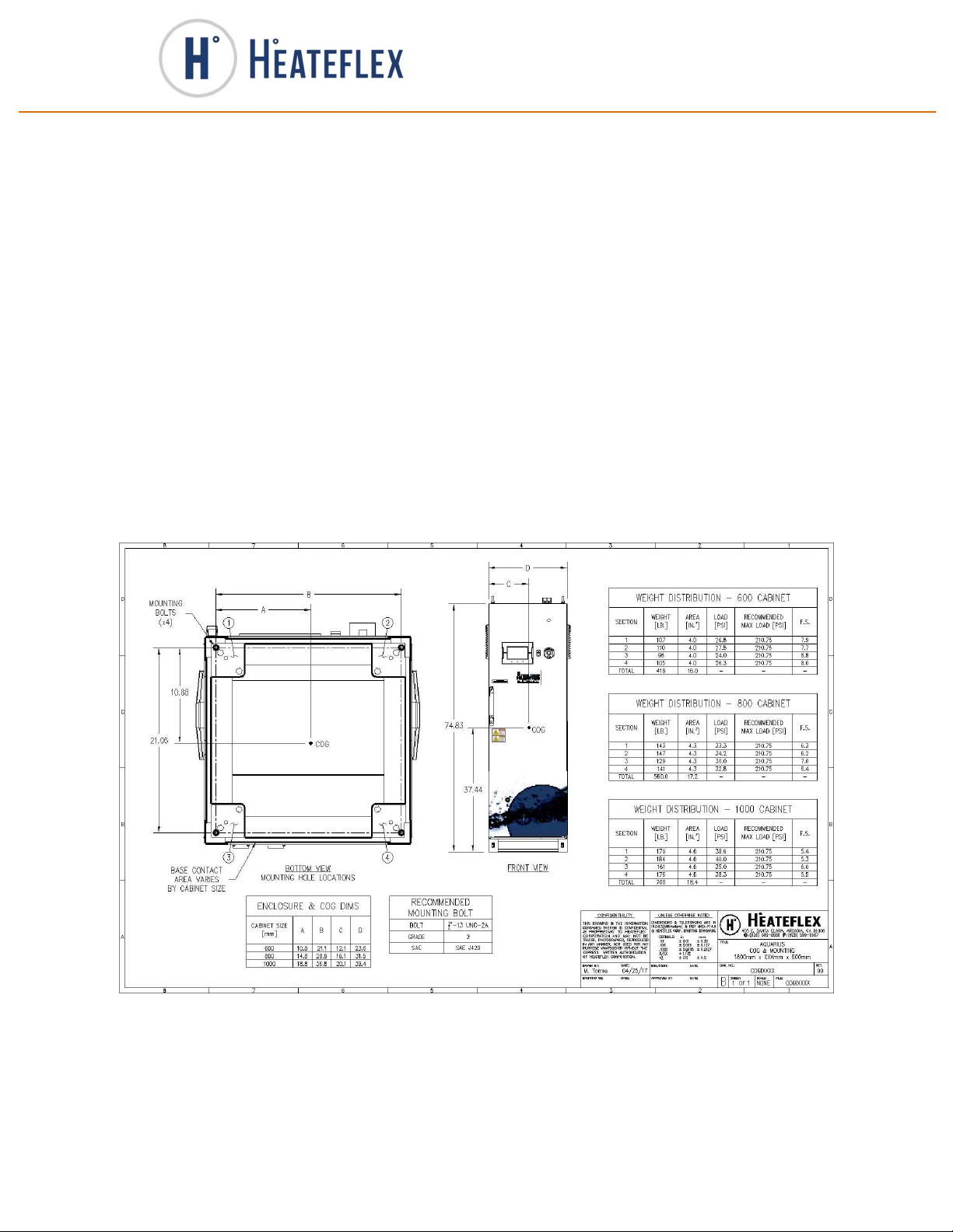
3. The unit must be secured using the included plinth base mounting brackets
to be compliant with SEMI S2-0715. It must be secured to the floor to
minimize possible tip over during a seismic event. See the figure below for
more information regarding unit attachment.
4. Connect the incoming and outgoing water lines. Use only the connection
types provided with the unit. (Refer to the drawing section of this manual to
for system connections.)

17
World Leaders in Ultra-Pure Heating
www.heateflex.com
405 E. Santa Clara St., Arcadia, CA 91006-7218
O
: (626) 599-8566
F
: (626) 599-9567
5. Connect the air supply lines and the purge or relief/vent water lines if
necessary.
6. Install incoming electrical power from main fusible disconnect (customer
supplied) to electrical compartment prior to being powered on. For point-to-
point connections see the electrical schematic drawings in SECTION II of
this manual. All switches must remain in the OFF position. See the
equipment specifications section on the Quality Control Documentation for
current rating, operating voltage, and type rating.
a. Customer Supplied main fusible disconnect switch must utilize Type
J low peak fuses. Consult Equipment Specifications in the Quality
Control Documentation for recommended amperage rating.
b. If Lockout/Tagout option is selected, Fusible Disconnect is provided.
Refer to drawing section of this manual for more information.
c. If a stationary appliance is not fitted with a supply cord and a plug, or
with other means for disconnection from the supply mains having a
contact separation in all poles that provide full disconnection under
overvoltage category II conditions, means for disconnection must be
incorporated in the fixed wiring in accordance with the wiring rules.
Compliance is checked by inspection.
7. Supply the unit with process fluid (and air if necessary). (Refer to the Facility
Diagram in SECTION II for more information.)
8. Start-up-procedure
a. Be sure all electrical switches and/or circuit protectors are in the
OFF position.
b. The Customer is responsible for connecting the Remote EMO
button (optional) according to the schematic diagram provided, or
using a jumper if no Remote EMO is to be used. (Maximum input
resistance is 600 Ohms)
c. Establish the minimum flow for your system; for information, see
the specifications sheet.
d. Turn-on Customer supplied Fusible Electrical Disconnect. Heater
power is available but the unit will not turn on.
e. Verify that the compact fused disconnect switch(s) are set to the
ON position. If light is detected on the compact fused disconnect
switch, the fuse(s) may be open and need replacing.
f. Turn on the unit (by pressing the “ON” button on the front of the
unit). The controller will load into the “STANDBY” mode. Please
note that the door must be completely closed in order for the unit to
turn ON.

18
World Leaders in Ultra-Pure Heating
www.heateflex.com
405 E. Santa Clara St., Arcadia, CA 91006-7218
O
: (626) 599-8566
F
: (626) 599-9567
g. The ALARM MENU key will be flashing to indicate unfulfilled alarm
conditions, which include but are not limited to the “High Limit,”
“Low Flow” and “Low Level” alarms. To clear these alarms
conditions, fill the unit with the process liquid until full. This will
satisfy “Low Flow” and “Low Level” alarms conditions. Press the
ALARM RESET key located on the Alarm Menu screen to clear
the alarms. The High Limit alarm will always be present upon
power up.
h. The customer needs to enter the “Process Temperature Set
Point” located in the Control Settings screen before the unit can
process. All the necessary controller parameters have been
Factory preset and can be modified if desired.
The customer needs to enter and/or review the desired “Process
Temperature Set point”, “Low” & “High” set points for
Temperature, Flow Rate, Pressure, and Resistivity (if the option
is available). These values can be found on the Alarm Set Points
screen. To modify these parameters simply press the data display
key to the right of the parameter description to be changed. If key
is grayed out, the user will need to log in with appropriate log in
credentials to modify these parameters. Select the Login Window
Key located on the upper right hand corner. Enter the password
into the keyboard and press the Return key. Next, select the
Process Temperature Set Point window, enter the desired set point
value, and press the Enter key. The set point value entered will
now be displayed.
i. Once all parameters have been changed to your specifications, go
to the System Status screen by pressing the SYSTEM STATUS
key located at the top right of the touch screen. The System Status
screen will allow the user to activate or “Run and/or Stop” the
heater. At this point the unit is ready to process. Press the RUN
key to start heating. The “STANDBY” label will switch to
“ACTIVE” and a green indicating light will illuminate green if all
safety devices are in a safe condition and no critical alarms are
present. The “HEATING” mode green indicating light will turn on
and flicker ON and OFF when heating is present.
Please note that for the Aquarius DI Water Heating Systems, the
unit will be defaulted in ““DEMAND”” mode. Please refer to the
Aquarius DI Water Heating System with Recirculation section of
this instruction manual for more information.
j. This unit will now supply D.I. water at the process temperature set
point that you have selected.
For more detailed information on the Aquarius control system and operation screens
please refer to the PF2000 Controller Manual.

19
World Leaders in Ultra-Pure Heating
www.heateflex.com
405 E. Santa Clara St., Arcadia, CA 91006-7218
O
: (626) 599-8566
F
: (626) 599-9567
System Shut Down Procedure
Before shutting down the Aquarius DI Water Heating System verify that doing so will
not adversely affect other equipment, machinery, and/or processes and that it is safe
to do so. Prior to powering down the system, place the Aquarius control system into
Standby mode. (Refer to the PF2000 Controller Manual for more detailed
information.) Once the unit is in Standby mode, power down the system by pressing
the OFF button which is located on the front of the Aquarius DI Water Heating System.
The indicating lamp on the ON button will de-energize and the touchscreen will turn
off. Please note that electrical power will remain present within the system until the
Aquarius DI Water Heating System has been disconnected from the electrical energy
source. To turn on the unit, simply press the ON button located next to the OFF button.
The Aquarius DI Water Heating System will always power up in the Standby mode.
It is ultimately the responsibility of the user to verify and provide adequate isolation of
all energy sources, i.e. electrical power, pneumatic air (CDA) and D.I. water. The
process fluid within this system may become pressurized from outside flow sources.
It is the user’s responsibility to verify that pressure within the system has been
relieved externally prior to servicing, in order to prevent exposure to hazardous fluid,
in this case, heated de-ionized water.
Certain energy isolation devices may be provided with the Aquarius DI Water
Heating System as an option, such as an electrical disconnect switch and/or pneumatic
AOV valves for process fluids. If provided, the electrical disconnect switch will be
mounted in an enclosure located on the back of the Aquarius DI Water Heating
System. If provided, the pneumatic AOV valves will be located inside the enclosure in
the heater/plumbing section. While energy isolation devices may be provided with the
Aquarius DI Water Heating System, it is the responsibility of the user to determine if
these options are sufficient and safe based on their requirements.
If the unit is to remain powered off for an extended length of time, it is recommended
to disconnect and isolate all energy sources to the Aquarius DI Water Heating
System, such as electrical power, pneumatic air (CDA) and DI water.
Table of contents
Other Heateflex Heating System manuals

Popular Heating System manuals by other brands

lapesa
lapesa RB-25 Installation and usage instructions

Cetetherm
Cetetherm Midi Wall TA Installation, service and operating instruction

Pentair
Pentair Mi Series Installation, maintenance and operation manual

oventrop
oventrop Multidis SFQ operating instructions

Hotstart
Hotstart OSE Installation & operation manual

Süd wind
Süd wind Ambientika Smart Configuration and user manual


Vasco
Vasco Energy plus Installation, use and maintenance instructions

Empire
Empire 682161 installation instructions

AERA
AERA AZURE WHEEL user manual

Lifebreath
Lifebreath METRO 120D installation manual

PAW
PAW HeatBloC MC45 DN 25 Installation and operating instructions

Aqua-Hot
Aqua-Hot 200 Series installation manual