0020096883_01 - 06/10 - Glow-worm
- 8 -
INSTALLATION
INSTALLATION
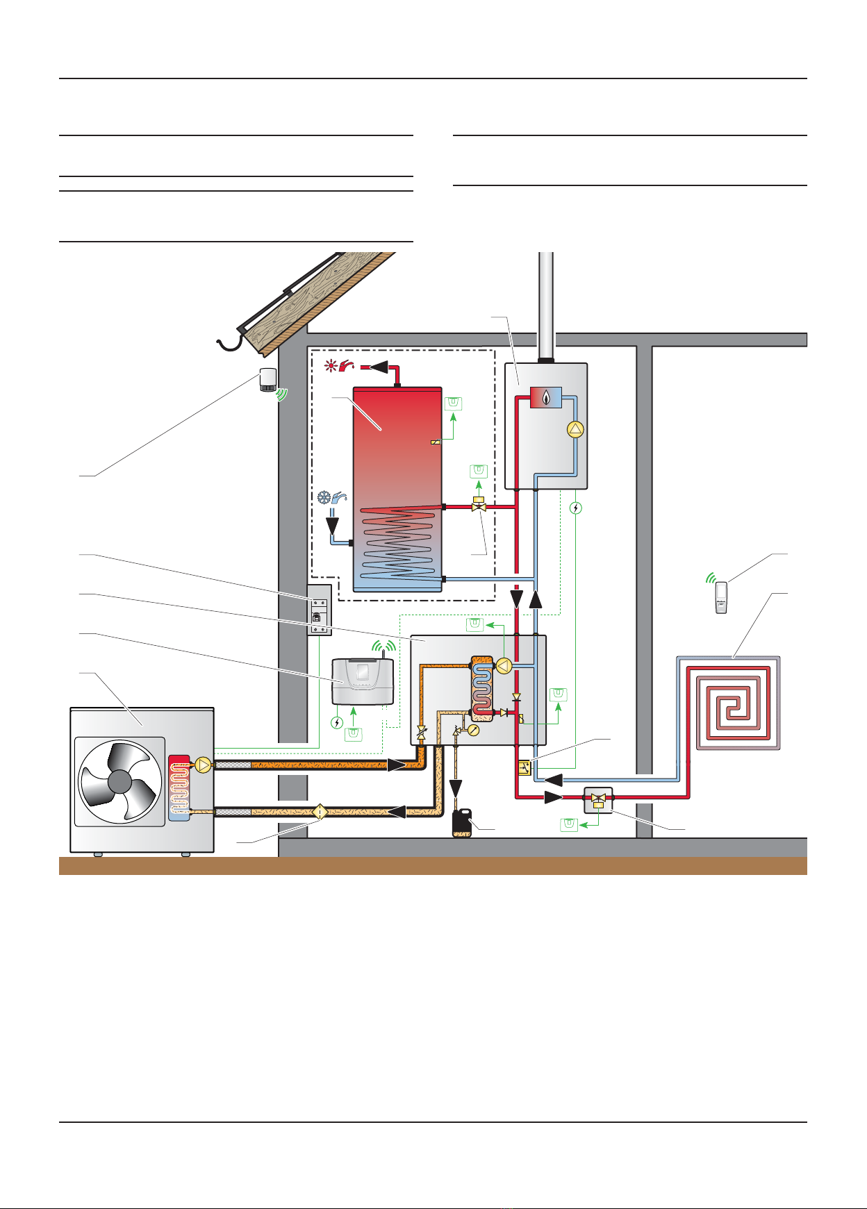
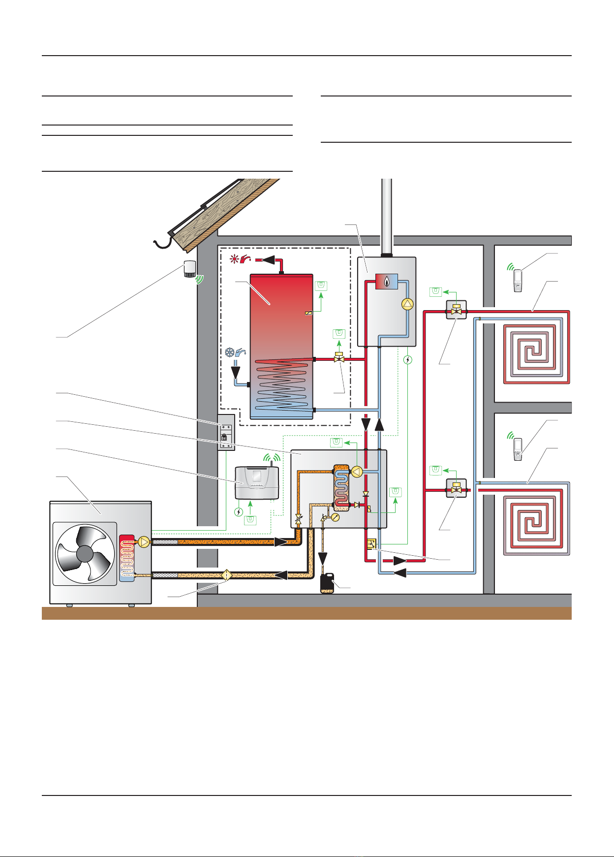
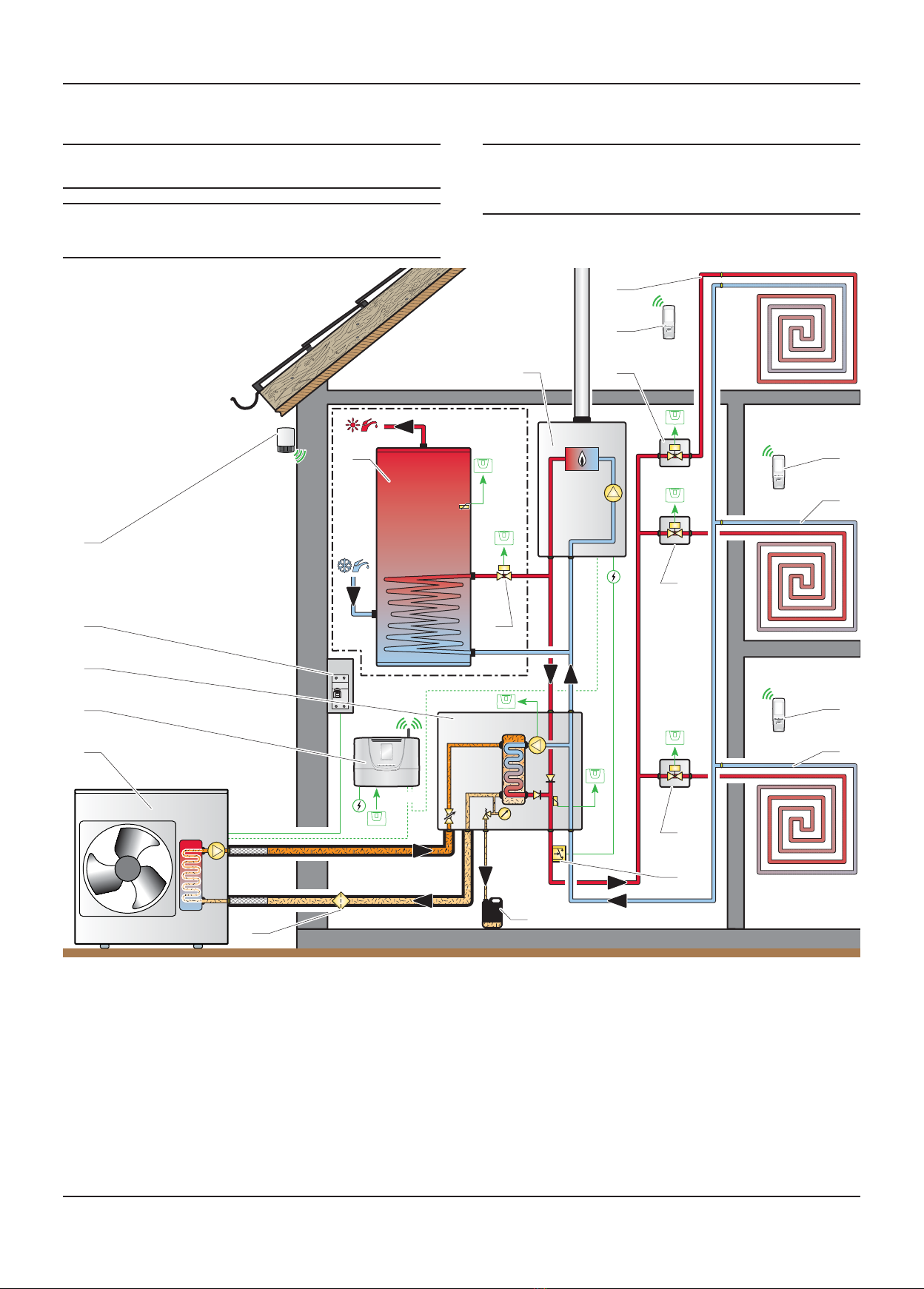
4 System appliance installation
4.1 Recommendations before installing
4.1.1 Heating circuit design
General
The heat transmitters may be low temperature (eg underfloor
heating or high temperature (radiator...).
The pipe sections are to be determined using a flow / pressure
curve (refer to the chapter "Activating the control unit" ►
Commissioning ►Heating circuit adjustment"). The distribution
will be determined by the flow corresponding to the power
actually required, regardless of the maximum power that can be
provided by the installation’s generators.
bWe recommend that you allow for sufficient flow
to ensure that the temperature difference between
the flow and the return is equal to 7 K for floor
heating and 15 K for radiators.
bMake sure the heating circuit water flow is greater
than 900 l / h.
Installation pipework must be designed and installed to ensure
venting of air from the system is possible.
bTRVs must be fitted on all radiators, with the
exception to reference rooms.
The total volume of water for the heating circuit depends,
among other factors, on the cold static load of the boiler’s
expansion vessel.
iThe heating system volume should be calculated to
ensure that the expansion vessel is suitable, it may
be necessary to add an additional vessel.
- In GB, Guidance on vessel sizing is also given in the current
issue of BS5449 and BS7074 Part 1.
iIn the event of insolating the boiler, the boiler
expansion vessel will also be isolated from the
heating circuit.
In such an event, adopt the necessary precautions.
It is recommended that a drainage valve be installed at the
lowest point of the installation.
- Drain taps shall be to the current issue of BS2879.
• Install the following components in the return of the heating
circuit (not supplied):
- a heating filter
- a ¼ turn shut-off valve,
- an air separator (if necessary),
- an anti-sludge filter (if necessary).
• In the case of a heated floor, install a manual reset overheat
safety device (55°C) on the heating circuit flow (refer to the
Chapter 2 - System description). Connect the overheating
safety device to the boiler power supply.
Water treatment
Existing system- It is essential that prior to installing the new
appliances the system is thoroughly flushed.
New system- For optimum performance after installation, the
appliances and its associated central heating system should
also be flushed.
Flushing shall be carried out in accordance with BS 7593, a
chemical cleanser can be used either Sentinel X300, X400 or
Fernox F3 are suitable.
It is recommended to flush existing systems first before fitting
the new appliances.
• Ensure all cleanser is removed from the whole system before
adding an inhibitor.
For long-term corrosion protection after flushing, an inhibitor
suitable for stainless steel heat exchangers can be used. Either
Sentinel X100 or Fernox F1 inhibitor can be used.
The module is suitable for use on systems using softened water.
4.1.2 Heat pump circuit design
Installation pipework must be designed and installed to ensure
venting of air from the system is possible.
bMake sure the circuit’s water flow corresponds
to the appliance’s nominal water flow.
• Install the following components to the hydraulic module, in
the direction of the heat pump (not supplied):
- a filter,
- a ¼ turn shut –off valve on each side of the filter,
• Install a ¼ turn shutoff valve in the flow of the heat pump.
iIn order to avoid the transmission of vibrations to
surrounding structures, use hoses for the hydraulic
connections at least 1 metre from the heat pump.
bInsulate the pipes with an UV- and high-
temperature-resistant insulation.
4.1.3 Domestic hot water circuit design
Water pressure
The maximum working pressure of the domestic hot water
circuit is 10 bar. If the cold water supply pressure exceeds this,
then a pressure-reducing valve must be fitted in the supply to
the boiler.
‘Hard’ water areas
In areas where the water is ‘hard’ (i.e. more than 200 mg/L
of calcium carbonate), it is recommended that the hot water
setting is reduced and that a scale reducer is fitted, refer to the
manufacturer’s instructions or consult the local water company
for additional advice.