Heath Company Heathkit HD-1410 User manual

HEATHKIT
MANUAL
for the
ELECTRONIC KEYER
Model HD-1410
595-1692-06
COMPANY •BENTON HARBOR, MICHIGAN

YOUR HEATHKIT 90-DAY LIMITED WARRANTY |
Consumer Protection Plan tor Hemthkll Consumer Products
'AKl^tyni' l.ilhl' Mfalh'jrriily 4fl» DcllBVff y.<u WiU rrl|i)> »JSfmrjl"«J yjUl >il ai*l
tif OloasoO wilti iH pw1cynia"i.e please 'eafl ConsumiB Piulecbon Plan c»ie
luMy II J5 aLIMITED W*«n*NTy as riolmea minc U5C-ieiiwns P'wTuci
warranii ana Fmeral T'soe CommissnKi Imp'Ovomenl Ad Tha nai'anlj gim
VCHj specific \f^\ TKl>ii^ and ytjumay alaohavB olftnngriiswhicnvarvlrom smtio
slalL'
Heath's ResponalUllty
PARTS —Rnplatemanls Itn 'acluf, aelCLhvu inns "ill no SUM)"!"'"'"'" *'<'*'y*'">'" 0*"''
pu'^lDSD f^epl^Cfrfncni parrs ate 4ar'a/>liri1 for iria remaining porbop o< ITw ongfP1«> "Vanlv
peiiotl *og t«iublain*llrTinly p«niai'i>i.H'UIIiHll«Wto"10«"»'>» WHItig cn lelHpfWiins «J al
leiSi Anfl HE iifiii cat sruppinq crunqn Id 91H inotc pint la rou tnymtwom Itit
KlU
SERVICE LABOR FwapvnM ol 40 aayj kcm inn rule ul puicFiase any maKunciiun cauuiii
by rjulunivw paFTn ur oniir Lf> design *iH be LorrKiM ainc criar^ployiju Yowiuti ijei-vp' inoumr
ni ,uu> iinpuniiu 10 itw Hoain lacioty any HoaUiUI dt^umc Ceniei (umis ul Vuriiacnnuiogy
f.it-LirtirthE.s Lurpoiaiiofii any '-i< ou' avi')o'ii«] oywseas disinbuto'^
TECHNICAL CONSULTATION Vou Mill <««» tiec consullalion un any problBm yuu nvoM
PK-oifiiB. m1(111 jtwrnib"! mui*ol yuui MealfWil (ytWuti Jmi Wofi us aiinoor »weun c»>
^tTy we LnDiiijI accvpl cOMKI call!
NOT COVERED -IKiicoirectiono'Mwmliiy fwi aOiusimwits cnwaiion inaiumaiiaaui
iiiiiiisutu aDuse if nsqugwKa ara mil covoiM by We wirfiniy Um ol conowva toKMr tno of
inaunauirionied "Kxlilir-alian dI irw p>Muci <ir ul any tumsbM compcneni mA vocl ir<> iwianly
in ift i^nii'my Thia Aarraniy dc** mLiuLiir rmmlhi'se^itHil to* inconyflni»nt» Iqm c4 uM
iuitwnw laiembfy sw ue liTnii munauinonimJ wrvite
IM nwiwily toy«> only Heain pioiiLn-tn anu is mil riJunJeC lu oinei Bquipmant wcwnponenis
lh«l AGustonier uws in CDniun<:Tian nfih cwr pfodi/cts
SUCH REPAIR AMU REPLACEMENT SMAll. BE IM£ SOLt REMEDY OF THE CUSTOMER
AN(J IHE.RE SMALL BE NO LIABILITY UN IHt PARI OF M6ATH FUR Afjy SPECIAL
INDIRIl.T INCIDENTAL OR CONStOUtN'PAL DAMAGES INC LUDING BUI NO' LIMI tEl)
TO ANy LOSS Of BUSINESS OR PROFITS WmiHER 1)R NQI FORSEEABLE
Snmasialesdonoliiiowlbcnii^iHjnMUmiiBlitviolincKlefiialVLaniiiquaniialilamAgM *oih«
above iin;iiAiion of uiciuBiun may nei aopiy '0 vou
Owner's nesponalblllly
EFFECTIVE WARRANTY OATE -W^'iitriiy ncginsun inirrme oltiisrconsomHtpurcnaw You
rnusi supply a rnpy iiT yiHi' prntf of pu'L.nase wfltn vou r^quesT Ma/ranly s«'vii:p cparT^
ASSEMBLY adiie sesking nwanly lennce yOu sHguU confilvle ifw assemoiy by taiehjUy
fiillf7MViiHj ihir inanuai insTruclinns Hfraitikii urviu aQvntias (dnnot compivie a^seniNy and
nllusimoMit inai iie cusiomei srasponoDiiiiy
ACCESSORY EQUIPMENT —Pwtnrmance rnailurvc1is<is inyMvmg anw pTun HBAiri a«et*o>v
«quipmpni laniennas auHio tomponunls tompulef pef>plnB>a's »"tj sol^*v« fl« Iare no!
'^ovefeo Ery Tl^s yfAfTanty an<) are Itit Awner sTbSpcnsiDilily
SHIPPING UNITS —Fi]iiD» trw pauirig insiiuctirnH pudsned mine asseneiy manuals Ovn>
Agt Ju^ 'u ii^actHQuatc paciiing j^annni be 'epaireo unaef yyarjamv
11 you ail) not salisfM wiin our setyne Iwan-an'y mulhenmsai 01 oui piooutis nie
directly 1(1 our OiecJoi al Cuslomer Stivicc Heain Company Benlon Hartiqr Ml
*^22 He will mahe ciirTflin yiiur priibiems 'eteive immeOiale personal aTnylifi
HEATH COMPANY PHONE DinECTORV
TtwloflPWEFig iQiaphone numdersare direcl Irres Ecirw depamrwiislisLed"
Kn orders and dMvsry inlonnDiion
CrMn
RMUwiwn Pam
161BI 982-3411
(616) 982-3561
I6<ei 962^71
BOOAM la4 30PU EST Wea*aaysOnly
Audio, (8181 9Sa-3310
Amaleur Rh5ki
Tesr Eriuipmeni Weainer indrLimimisarid
HoiTia CDOis
TelBvsio'^
Airoan Marirw. S«curitv Scannns. Auipmollvi,
AppiiKcas and Gonarai Ptooucis
CompuiBrt —HardyirarB
Conipuiais —SaDwaiB
Opwaong SysMmt Languagm. UtHinn
AoDlicalion PRwamt
(61GI 962-3315
(61 E) 3B2-3307
(6161 982.3496
(6161 982*3309
<616| 982-3860
(61 B) 982-3884
Prices and specifications subject to change without notice.

Heathkit® Manual
tor the
ELECTRONIC KEYER
Model HD-1410
595-1692-06
HEATH COMPANY
BENTON HARBOR, MICHIGAN 490 22
TABLE OF CONTENTS
Introduction 2
Parts List 3
Step-by-Step Assembly
arcuit Board Assembly 15
Paddle Assembly ,26
Chassis Assembly 30
Paddle Wiring 33
Front Panel Assembly 34
Rear Panel Assembly 33
Final Wiring .43
Knob Installation 4S
Tests and Adjusbnents 46
Final Assembly 49
Installation 52
Operation 54
In Case of Difficulty 55
Troubleshooting se
Specifications 53
Circuit Description 30
Circuit Board X-Hay Views 64
Circuit Board Voltage Chart 66
Chassis Photograph 67
fdentification Chart 33
Schematic ... (fold-out from page) 71
^'Varranty inside front cover
Customer Service Inside back cover
ConyrlghtO \VK
Printed in U.S.A.
Page 2
INTRODUCTION
The HO-1410 is acompact Elaetronk; Key«r vnth abuilt-in AC power supply,
mechanical paddles, sidetone oscillator, and speaker In one package. It is
designed and styled to complefnent the "SB" Series, and is compatible with
virtually sH modern trummltten md truwalven, as well us moix oUar
The following faeturviinirite the EkMtronie Keyer versatile:
•"lamUc" operation -Leu you fonm many Morse code characters
with lass wrist movement ^an is required with keyers that tack this
feature. If the two independent peddles are treated as one, operation
is identical to singte-paddie keyers with dot and dash memories. Dots
and dashes are self-completing, and proper ratio Is always
maintained.
•Built-in sidetont osdllator and speaker with adtuctebie tone and
volume.
•Headphone iack on the rear panel that silences the speaker. Recaivsr
audio fed to the headphones by aseparate rear panel jack.
•Solid-state output eliminates the bounce and sticking problems
associated with relays.
•Weighted cabinet to prevent the keyer from stiding on the (grating
surface.
0Rear panel jacks are provided for an external key, and for operation
from an extemat battery (polarity protected) for portable operation.
The line cord dtscofmaots from Electronic Keyer for battery
operation.
•Front penel "HoM" switch allow* transmitter tune>up.
Low profile styling and small size permit the Electronic Keyer to be set in front
of most ham rigs and not block controls or take up valuable space. The
versatility and reliability of this K»yer vM make It awetoome addition to your
ham f^rtlon for years to coma.
Built-in paddles have excellent "feel" and are easily adjustable for
tension and travel.
Refer to the "Kit BuUdera Quide" tor Information on parts Identification,
toola, wiring, and 9olttertng.
Page 3
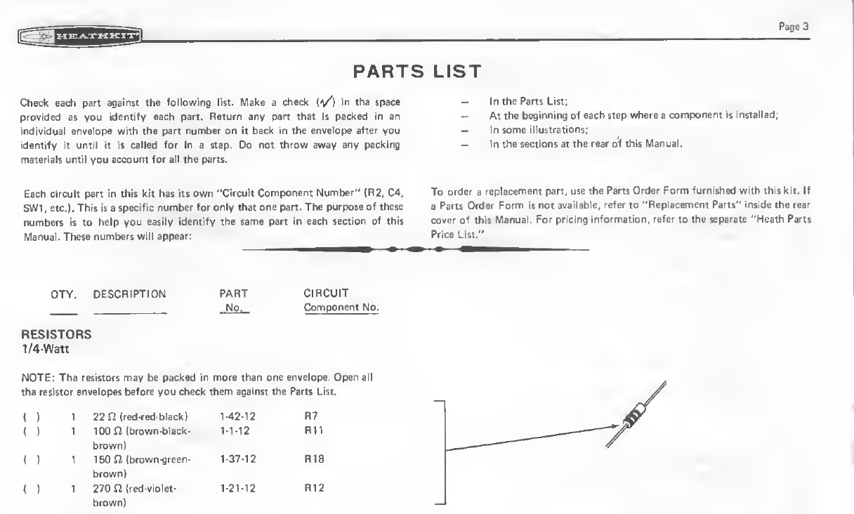
PARTS
Check each part against the following list. Make acheck (v^) in the space
provided as you identify each part. Return any part that is packed in an
IndiividMri vrvv^ope with tiie part numbar on it bwk In ^^lytl^ after you
idwRffy ft umit it it caM«d for in aK«p. Do tm- iSmm mm any padtinfi
iriatariais until you Mcwunt fiir all tht pirta^
6Mh tircult part in this kit has its own "Circuit Component Number" (R2. C4,
Siii, m*h Tlii9 i»a apMific number for only that on« pact, tb* purpow of tftm
nmbm H10 hatp you aasily Idwitify the same part hMefien of vih
Manual. ThMa numban wrtll ^spaar:
QTY. DtSCRIPTION PART CIRCUIT
,1^0. pgrn^nant No.
NOTE: The resistors may be packed in more than one envelope. Open all
tha resistor envelopes before y0»:«M#llHiffl the Parts List.
(1122iri(red-fed-black) R7
()1100 n(brown-black- 1-1-12 Rll
brown)
<f11-37-12 RI9
1270 n(red-violet- 1-2M2 R12
brown)
LIST
-In the Parts List;
-At the beginning of each ttqs whan aeofflpoiwnt It fnsteHad;
-In soma illustrafons;
To order areplacement part, use the Parts Order Form furnished with this kit. It
aParts Order Form is not available, refer to "Replaoernent Parfs" i^ruide tlie rear
cover of this Manual. For prlcine «ii9|i9latie«Vli**t^#l<>*««^^
Price Lilt."
Page4
PART CIRCUIT
Wp. Component No
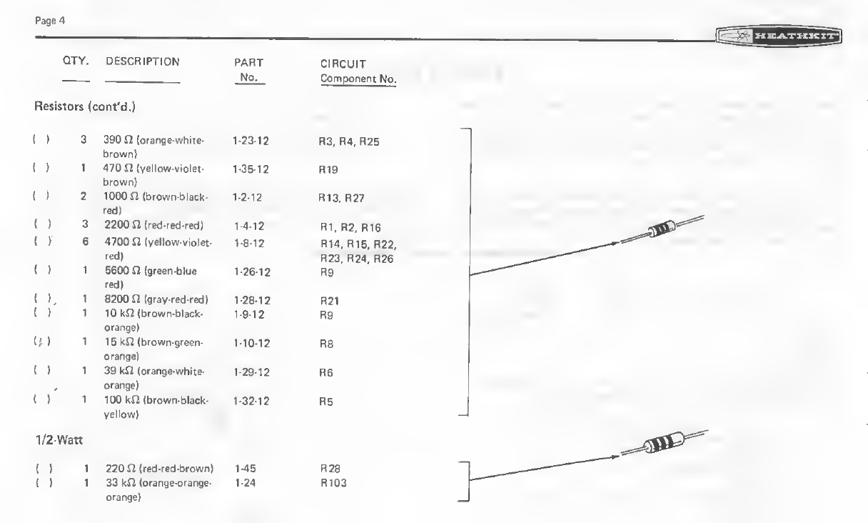
RMistori (cont'd.}
in 3390 (oranse?vvhtte< 1^23-13
brown)
i*
)
'
1470 n(v<itl6HHA0let-
brown)
1-35-12 R19
i'
)
21000n(brown^lack' 1-2-12 n10r n^/
rad)
all 2200 m(rad^'Tad
)
1-4-12 R1, R2, R16
(. f64700 a(y«^Gw^Vl6l«^ 1-8'12 R14. R15, R22
red) R23, R24, R26
1
red)
1*26^12 m
(K18200 nIgrav-redTBd) t^12 R21
{ ) 110 kn (brown^tvck- R9
1R8
n4 orange)
139 kn loranga-whtt«> 1-29*12 R6
orange)
1lOOkA (browrv<bl«^-
y«lkniv)
1-32-13 no
V2-Watt
(if 1220 n(red-red-brawR) R2e
(If 133 kn (orariBe-oranga- 1-24 R103
QTY. DESCRIPTION PART CIRCUIT
WPi Component No.
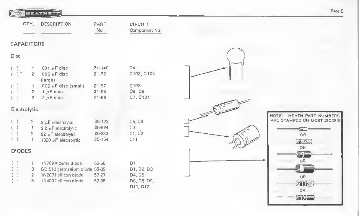
CAPACITORS
Dbc
( ) 1,001 IJ.F disc 21-140 C4
()' 2,005 nF disc 21-72 C102, C104
(large)
{). 1.005 liF disc (small) 21-57 C103
(r&.tfiF disc 21-9$ ce, eg
(r2.2 AtF disc 21-99 07, 0101
( ) 22electrolytic 25-123 C5, 06
( ) 12.2 fxF electrolytic 25-924 C3
( ) 222 fiF electrolytic 25-233 CI .C2
(.) 1100Q eiijctrptytie 25-164 Gil
()11N709Azenerdija(W^^56-S8 D7
()3GD-510 germanium diode 56-89 D1, D2, D3
()21N2071 silicati diode 57-37 D4, D5
()51N4002silicondiode 57-65 D6. D8, D9,
D11.D12
Page 5
PaQsQ
QTY. DESCRIPTION PftftT CIRCUIT
^Wft. Component No.
TRANSISTORS
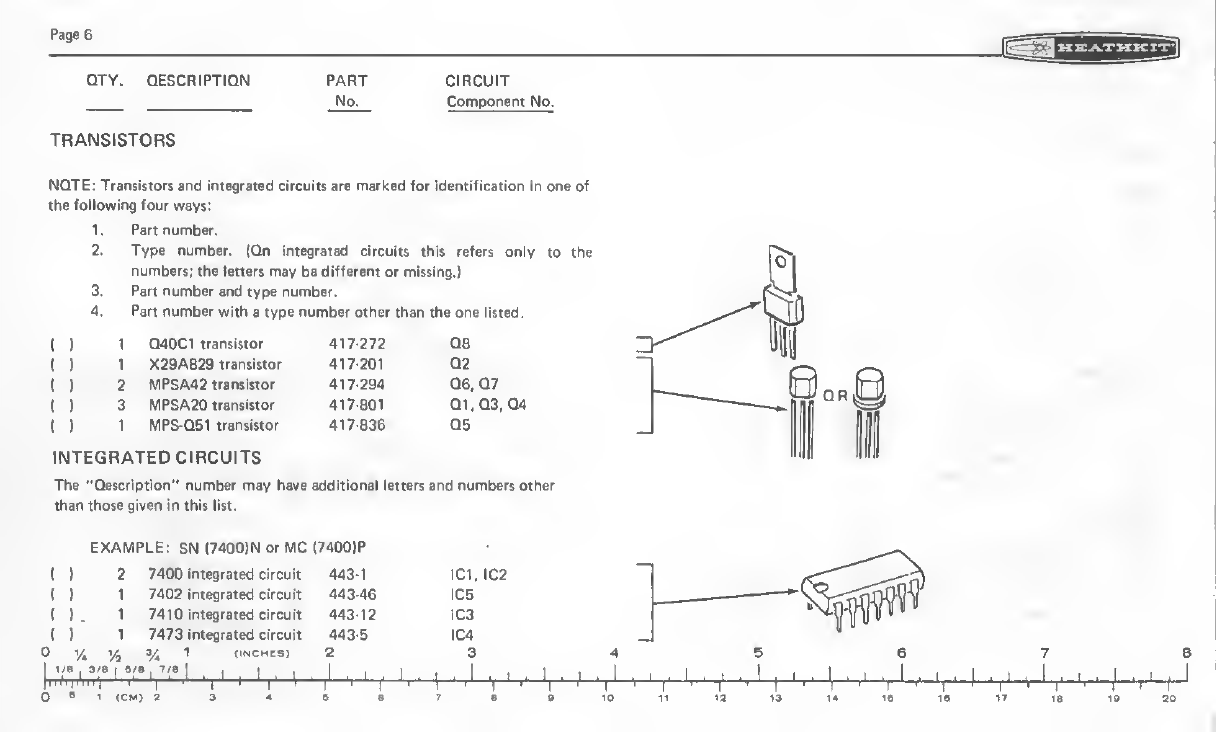
NOTi: Trsraiitpn and integnttad clFOuIti ire marked for Identification in one of
lilt Mowingfour ways:
1.Part number,
2. Type number, (On integrated circuits this refers only to the
numbers; the letters may be diffarent'br misting.)
3. Part number and type numbart
4. Part number with tt typt^mmiM' othar than the one llited.
()1D40C1 transistor 417-272 Q8
{)1X29A829 transistor 417-201 ^Q2
(I2MPSA42tramiitor 41>tt»* ~'"l^-d?--
I)3.^,.vMPSA20tran»liior 417-801 Q1,03;04
(r1MPS-D51 tramlttor 417-836 05
INTEGRATED CIRCUITS
The "Description" number may httdiaddltiobAill^i^tnd mmibari Other
than those given in this list.
EXAMPLE: SN (7400)N or MC (7400)P
(127400 integrated circuit 443-1 IC1, IC2
(117402 integrated circuit 443-46 IC5
( ) .17410 int^rated circuit 443-12 1C3
( ) 17473 integrated circuit 443-S IC4
0%>& 3yJ 1(INCMtS) 23
1/8 ,3/e (B/B IT/B I.
I, I , I ,I , T,I
}1t&A) aa- 4. sat•»to

QTV. DESCRrPTrON
CONTROLS
()1750 acontrol 10-934
()1100 acontrol With >
switch .- ..
()1SO kn control with td^7d4
switch
CIRCUIT
Component No.
R17
OTHER ELECTRONIC PARTS
(') 1Power tr&nsformer
(i1Neon lamp
()11/16-anipere, slow-blow
fuse
(f1Speaker
WIRE-SLEEVING
I ) 12" Bare wire (For soldering
iron tip)
(r36" Black wire
(f36" Red wire
;( J|, 36" Large brown wire
{"f 96" Small brown wire
()1" Small black sleeving
()6" Large black sleeving
()96" Shielded cable
(11Clear sleeving
il" length)
{)1Line cord
54-878
412-15
421-27
340-n
344-15
344-16
344-34
344-61
346-1
346-20
343 1
1
346-26
Tl
PL1
Page?
Pages
QTY. DESCRIPTION PART CIRCUIT
,JiOx. Cotnoonant Nft.
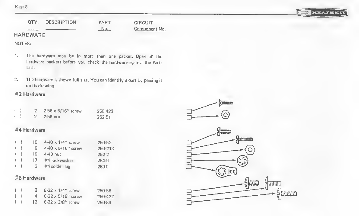
HARDWARE
NOTES:
1. The hardware may be in more than one packet. Open atl the
hardware packets before you check the hardware against the Parti
2. The hardware is ^mf^mMu. You ean .WMpyt|»Mt»y |ifacing it
on its drawing.
#2 Hardware
1122-56 XB/16" screw 260422
I)22-56 nut 262-6t
#4 Hardware
( ) 10 4-40 X1/4'' screw 2S0-S2
{)94-40 X5/16" screw 250-213
()19 4-40 nut 252-2
()17 #4 lockwasher 264-9
amnla #49oldar(ug
#6 Hardware
()26-32 X1/4" screw 250-56
()46-32 X5/16" screw 250-432
()13 6-32 X3/8" screw 25&e9
PART
No.
CIRCUIT
Component No.
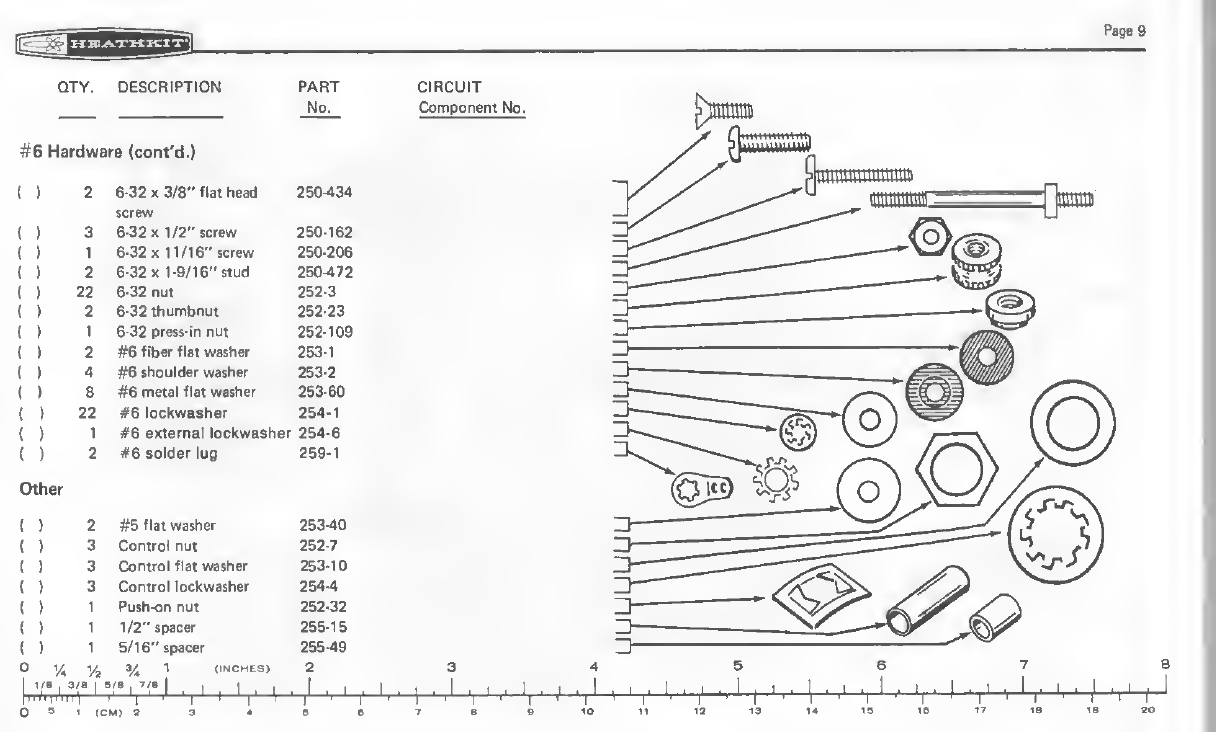
#6Haixlwam(confd.)
()7B-32x3/8"fl«,hili|^ mm
screw
( ) 36-32 X1/2" screw 250-162
I ) 16-32 X11/16" screw 250-206
()26-32 X1-9/16"itud 250-472
f
I6-32 nut 252-3
( ) 2&-32 thumbnut 252-23
i)16-32 praw-ln nut 262-109
()2#8 flbw flat wnher 263-1
()4#6 shoulder washer 253-2
( ) 8#6 metal flat washer 253-60
()22 #6 lockwasher 254-1
( ) 1#6 external lockwasher 254*6
()#lfie»old«r lug 2S9-1
Other
(2#5 flat washer 253-40
(3Control nut 252-7
13Control flat WMher— mm
(3Control lodcwa^er 254-4
(1Push-on nut 252-32
(11/2" spacer 265-15
(15/16" spacer 255-49
0'/2 3^ 1(INCHES) 2
I04(cw a94si7'B

Page 10
qty; ENmiprtoMi pmt circuit
—Ma. Component No.
Ottipr {eonfd.)
()11/16" spacer 255-74
{)4Rivet 256-15
()1Wire spring 258-179
CONNECTORS
t): 1Male connector housing 432-148
(f1Female connector housing 432-149
()2Male terminal pin 432-854 J,
(I2Female terminal pin 432-8S5
(I 1AC power socket 432-4
()3Phono socket 43442
(4- SIC socket 434-298

QTY, DESCRIPTION
Connectors (cont'd.)
()
()-
1Phone jadt
.% phone plug
3,PH^pnaQ,
436-21
438-3
43846
CIRCUIT
Componant No.
METAL PARTS
()2Cabinet shell 90-1133-2
{)1Right side panel 200-1212
(}1Leftsidepanel 200-1211
r
Page 1
1


OTY. DESCRIPTION PART
Ma.
( ) 2Paddle lever 266-843
<11Lead weight 266-846
1>4Contact plate 469-21
MtSeELLANEOUS
I 1
'J
JBinding post bssG 75-17
i)4Cabinet nut 75-61
!f!T 1Small insulator paper 76-108
1-3/4" X2"
{') 1Large insulator papw 7Bn10S
W-V" 1w
3-3/8" X5-3/8"
{. )1Circuit board 85-1524-2
U)4Plastic foot 261-34
{»1Cam lever 26e«M
()1Cable tie 364-6
{11Fted lens 413-10
( ) 1Fuseholder 422-1
()1Terminal collar 431 82
( } 2Knob bushing 455-633
()2Paddle knob 462-931

Page 14
QTY.
Miscellaneous (cont'd.)
i)
i)
"TV
CIRCUIT
Component No.
Round kno& 4e2-^
ICHfter 490-111
Nut starter 490-5
f)1Fuse replacement label 390-1255
NOTE: Be sure vou refer to the numbers on the blue and white label in
any communications you may have about this kit with Heath Company.
You may w^nt tojm||$ |hs> iir|gti|e^
{)
1Blue and white label 391-34
1Parts Order Form 597-260
1Kit Builders Guide 597-308
1Manual (See front cover for part
numb«r.l
Solder

STEP-BY
B*fora you start the "Circuit Boanl A»«nbly" be sura to readivUw "Circuit
Bos«! Fam Meunting" and 'SnUS«^'''m0mi>f il^9 ''»C% IHlHitfWf'SuWft.'*
CIRCUIT BOARD ASSEMBLY
Due to the small foil area around circuit board holes at integrated circuit
sockets, and the small areas between foils, use the utmost care to prevem soklL'r
bridges between these adjacent foil areas. Use only aminimum amount of solder,
imd do not heat components excesstvety with the soldering iron. Diodes,
transistors, etc., can be damaged if subjected to excessive amounts of imkt„
Apply the soldering iron only long enough to make agood solder connection. *'
NOTE :When you solder integrated circuit sockets you will need asmall wattage,
small-tip sotdertng iron. If one of these is not available, piui:t.'i'il ,is follows: Be
sure your soldering iron is cool. Then wrap the large bare wtru. bupfilied with this
kit, tightly around the soldering iron tip as shown in Figure 1.Allow
approximately 1/4" Qf ^rife .j;a;aKtjiO0 i>^onc| the end oUh^ soldering iron. Cut
the wire end to'«aii|Sd^#W|MM«i^8^ the
Page 15
Besi»tors will be called out by the reslmnce value (in nor kSl) and color code.
Capacitors wilt be called out by their capa^tSrRSe velue (in nP) and type (disc,
tantalum, or electrolytic).
SAFETY WARNING: Avoid eye injury when you clip off excess leads. We
suggest that you wear glasses, or at least clip the leads so tfui eotis WiH not fly
Kiward your eyes. I
V-
BARE
WIRE TIP
SOLDER
Figure 1

3030
FcHitlon the circuit biurd as shown.
NOTE: DIODES MAY BE SUPPLIED
IN ANY OF THt FOLLOWING SHAPES
ALWAYS POSITION THE BANDED END
AS SHOWN ON THE CIRCUIT BOARD,
IMICIEH
(')D4 and D5: Two 1N2071 diodes
(#67-27».
(1D7: 1N709A zener diode (.75G 581.
()D6, 8, 9, 32 and 11; Five 1N4002
diodes l#57-65).
1)Solder the leads to the foil and cut
off the excess lead lengths.
FOR GOOD SOLDER
CONNECTIONS. YOU MUST
KEEP THE SOLDERING
IRON TIP CLEAN.
WIPE IT OFTEN
WITH ADAMP i^^SL
SPONQE OR CLOTHT*^*^ ti. v
CONTI NU E
NOTE: Use 1/4-watt resistors (the smaller
resistors) unless directed otherwise.
)R27: 1000S2ibrown-black-redl.
)R21:8200n(grav-red-red)
1R22: 4700 n(yellow-viofet-red).
IR26; 4700 n(vellow-violet-rBd).
R25: 390 £2 (orange-white-brown).
R24: 4700 Q(yelloWMHDlBt-nd>.
)Soldw the iMds to tfie foil and tan
off the flxcasa lead lengths.

iL
()Remove all the insulation from a
15" length of small brown wire. Cut
this wire to the Indicated length
whenever astep calls for bare
wire.
NOTE: Be sure to position each of the fol-
lowing jumper wires as shown.
)rbare wire.
3/4" bare wire.
)1" bare wire.
)rbare wire.
rbare wire.
^)rbare wire.
Solder the leads to the foil and cul
off the excess lead lengths.
1—Ml
()1" bare wire.
WCTOfilAt 1-2
CONTINUE
1-1/4" bare wire.
3/4" bare wire.
)rbare wfre.
3/4" bare wire.
( 1 2-1/4" bare wire. Be sure this wire is
positionsd over the outline on ttie
circuit board and does not touch thp
other nearby [umptr.
3/4" twe wire.
)Solder ihe leads to the foil and cut
off the excess lead lengths.
^y* Va y* {(NCHES) 2345678
11/e .3/8 1B/B ,T/e I
1' 't '*-4^ '
'l ll 'I'l ^'['l' [, 1' 1' l| ,1 i^ \if-
s4sBTBft 10 11
1'1^ '1
IS 14 IB ^ti

Pas* $9
1)R19; 470 n(v«llovirvfol«-brown).
()R3:390n (orangv-whitc^rown )
.
'1Rv'i i/ni
()Hit, v^m 12 ',rr(i n'd rrdi
{1R15; 4700 ii (vflli-w vmh in^d).
(tf R14:4700n(villowviol«t-recl).
[)R11: 100 it tbruwn-black-brown).
( ) R13: 1000n(brown-btick-nd).
( 1 R28: 220
brown).
n, 1/g-w«t tred-red-
( 1 R12: 270 Ii Ired-uiolet-brown).
()Solflpc thi;
1)1- rl.f ,.M
li'Ltds to ihi> toil dPid cui
A|r' id Ir-I |i|tl !.
CONTINUE^:
PICTORIAt 1-3
R9: Use 5600 S"! {gri!i;n-blue rcd) for
10 to 60 words-pet -minute speed.
Use 10 k£2 (brown-black-orange) for
10 to 35 words-per-minute speed.
(Disregard the value printed on the
circuit board, if any.)
[V') Sekler titHWlNMtfr foil and out
Off $N mm >««t
Table of contents
Popular Other manuals by other brands


HELVAR
HELVAR 492 installation guide

Digital-Ally
Digital-Ally DVM-500Ultra installation instructions

Fiap
Fiap SpaltSkim Active Series manual

Comeup
Comeup CWL-301L instructions

Goclever
Goclever CITY BOARD 65 CYCLOPS BLACK quick start guide

Siemens
Siemens 3AH Instructions, Installation, Operation, Maintenance

Elaflex
Elaflex ZVA Slimline 2 How to use

Yvolution
Yvolution Neon Cruzer Series manual

Aqua Medic
Aqua Medic YASHA Operation manual

I.SOUND
I.SOUND DUAL CHARGE USB Product features

OIC Korea
OIC Korea MICRO-ADJUSTABLE PULL-OUT Installation and user guide

Aero-motive
Aero-motive 11207 installation instructions