Heath Zenith Chime Extender 6157 User manual
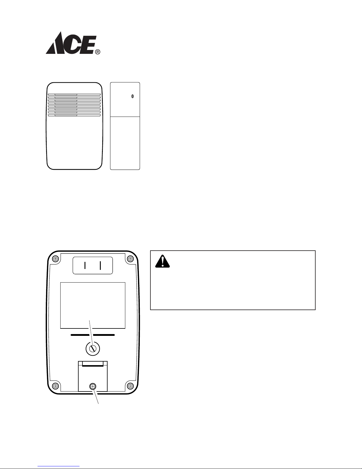
Chime Extender
Model 6157
This package includes (Style of chime extender
and chime may vary from illustration):
• Wirelessplug-inchime
• ChimeExtender
• Hardwarepack
The chime extender requires 4“AAA”alkaline
batteries (not included).
YourACE®ChimeExtenderallowsyoutoadd
doorbell coverage to any room in your house
withouttheneedtorun additional wires.The
ChimeExtender“listens”foryourexistingdoorbell
to ring, then transmits a radio frequency signal
totheplug-inchimeunitinanotherpartofthe
house.Note:TheChimeExtendercannottellthe
differencebetweenthefrontdoorandreardoor
tunesofyourexistingchime.
©2008 598-1070-04
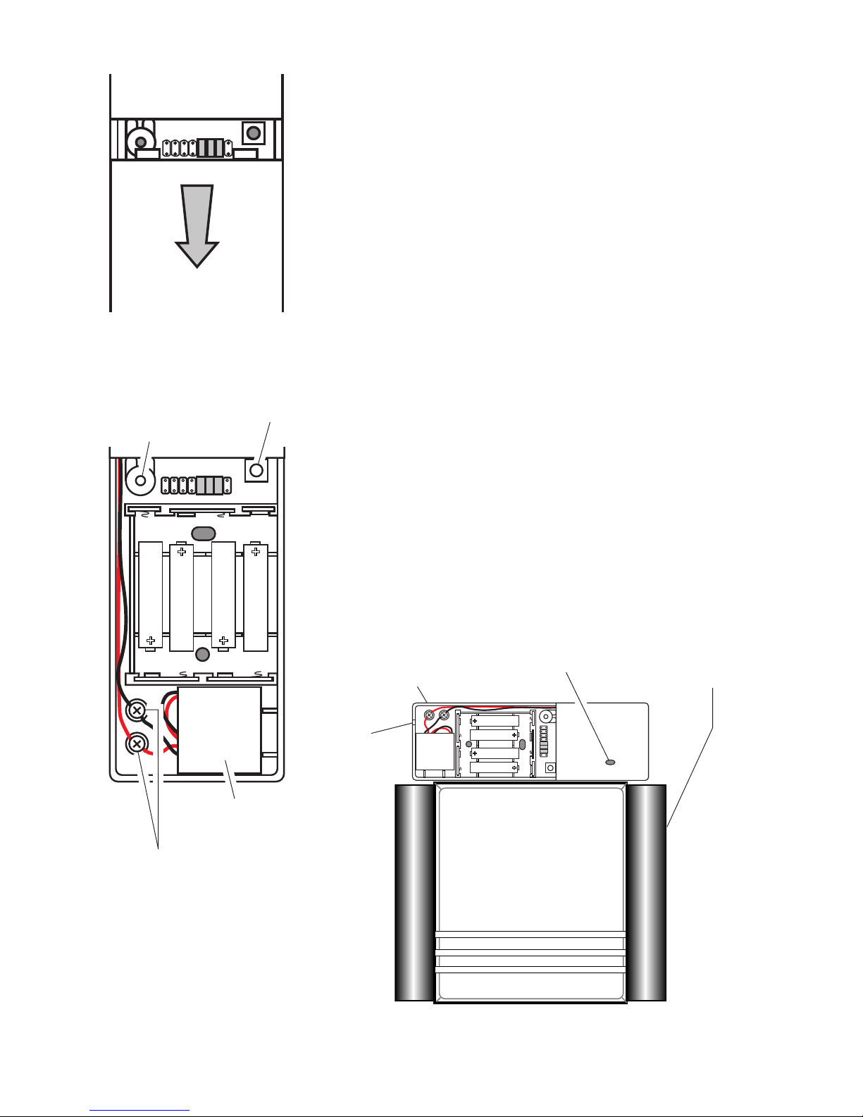
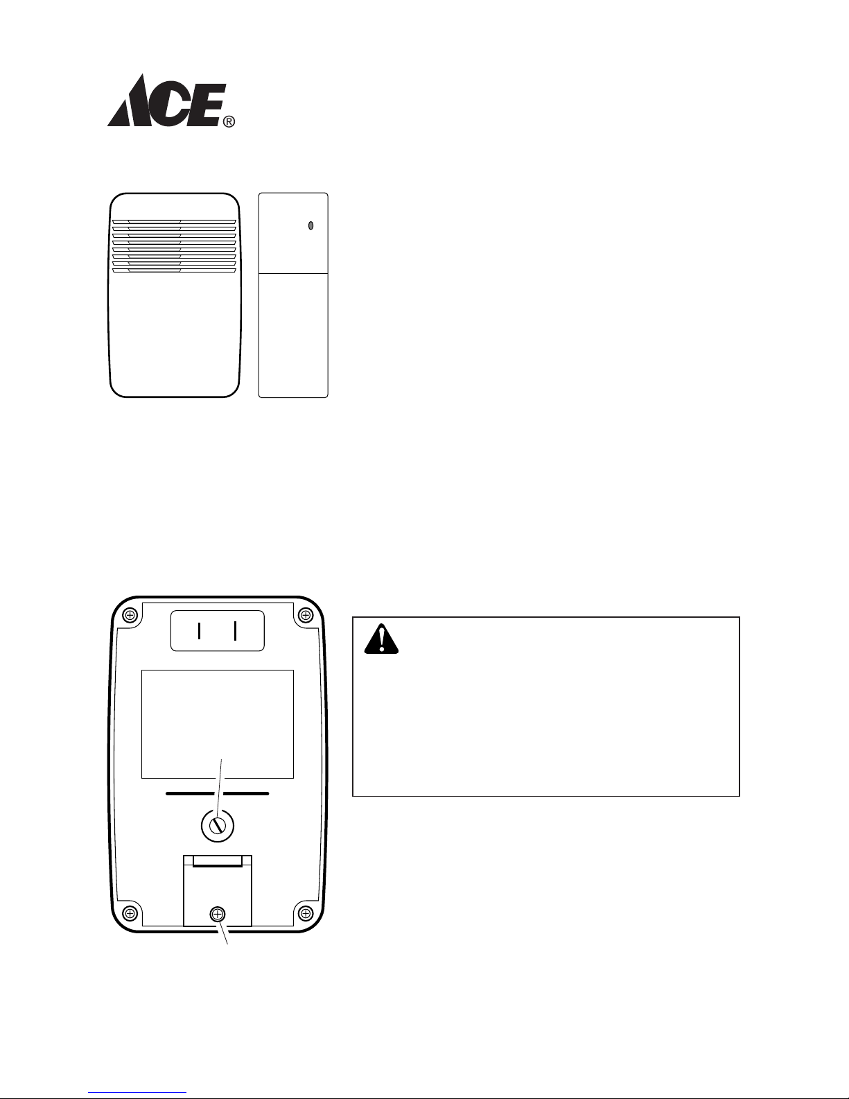
Figure 1
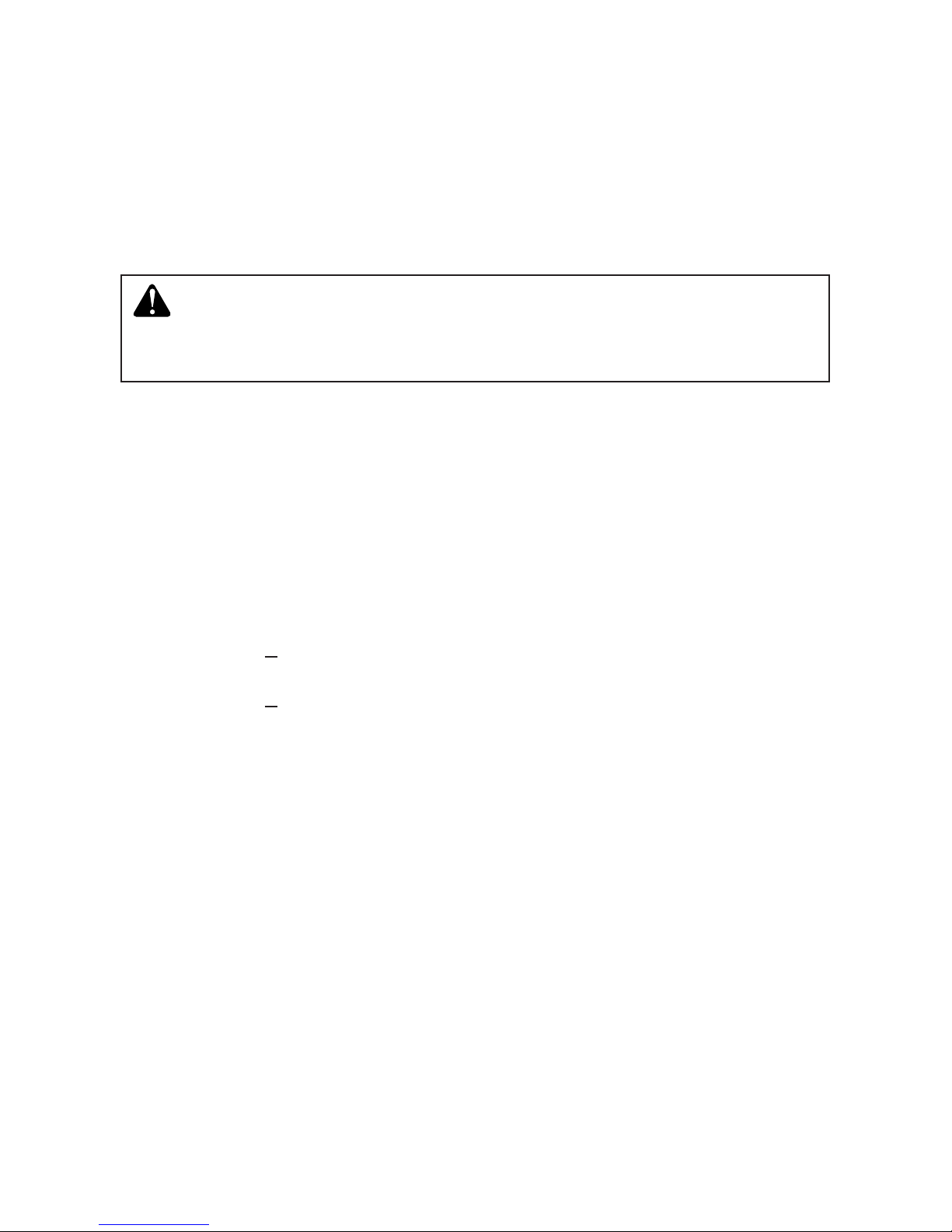
WARNING: To prevent possible
SERIOUS INJURY or DEATH:
NEVER allow small children near batteries.
Jumper Access Door
(SeeTuneorCodeSection)
1. Plug in wireless chime. To reduce the risk of
electrical shock, this equipment has a polar-
izedplug(onebladeiswiderthantheother).
Thisplugwilltinapolarizedoutletonlyone
way.Iftheplugdoesnottfullyintheoutlet,
reversetheplug.Ifitstilldoesnott,contacta
qualiedelectriciantoinstalltheproperoutlet.
Donotattempttobypassthissafetyfeature.
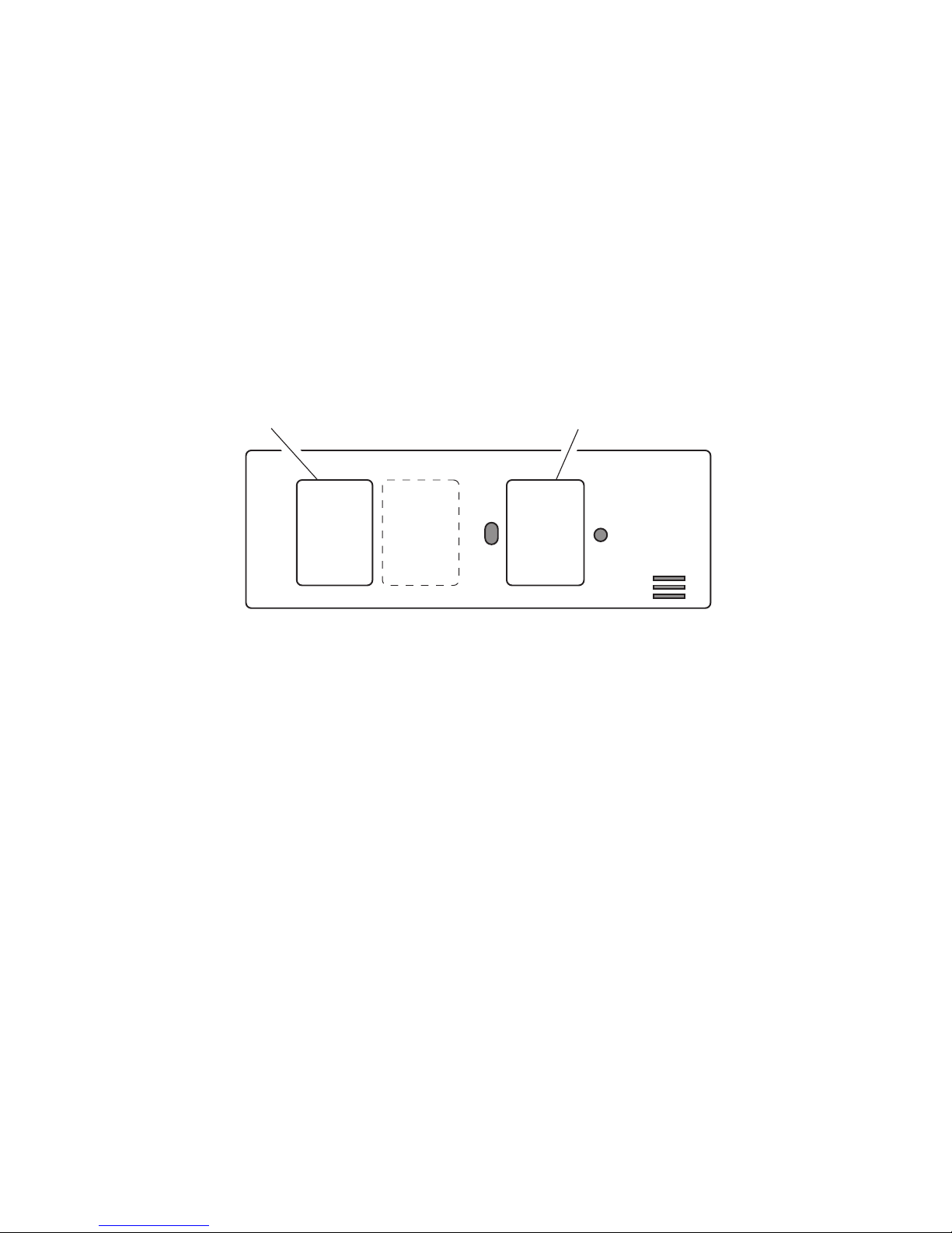
ChimeVolume
Control
(SelectedChimes)

-2- 598-1070-04
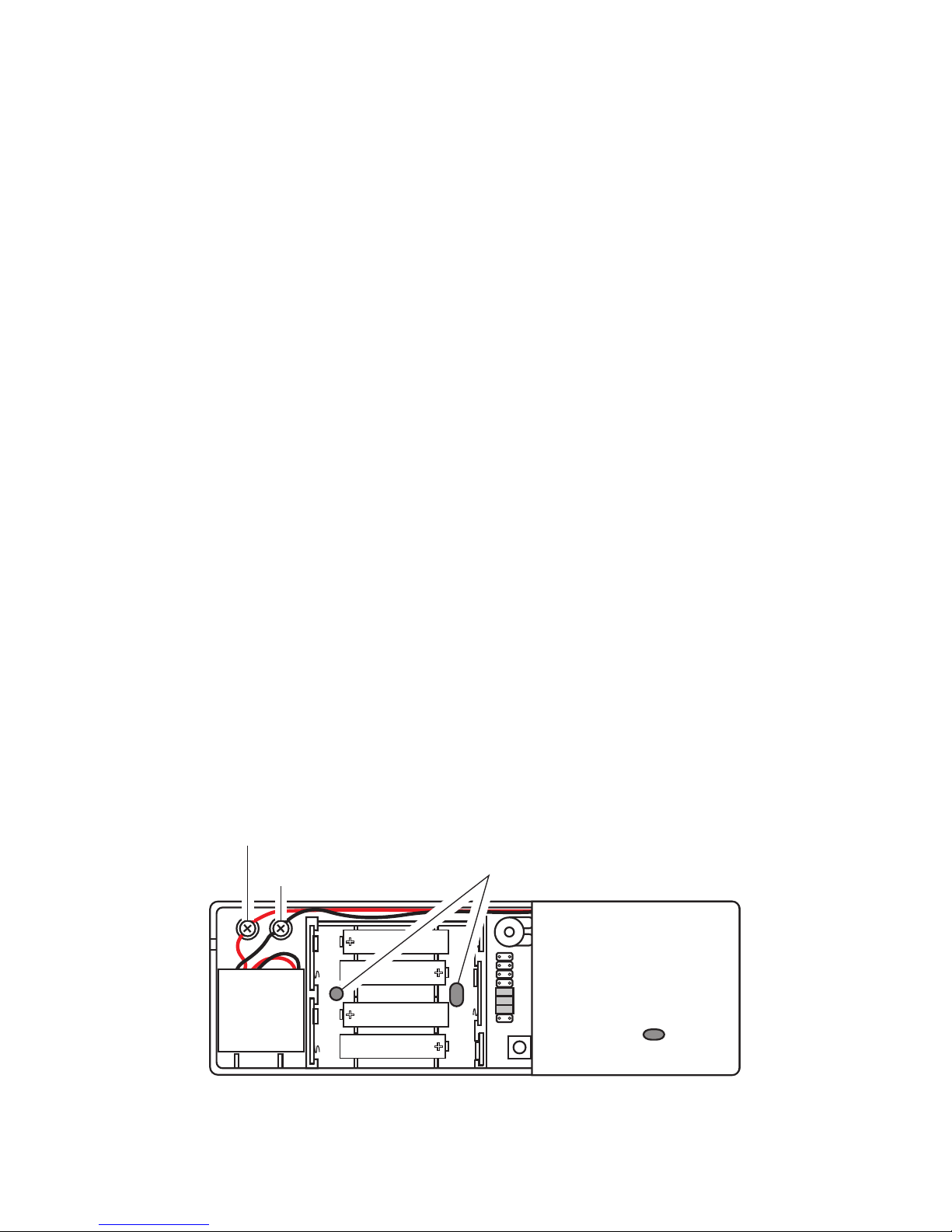
ExistingChimeChimeExtender Transmit Light
Figure 4
12345678
Figure 2
2.
Open chime extender case.Pressoncoverwithyour
thumbandslidecoveroffasshowninFigure2.
3. Install 4 “AAA” alkaline batteries (not included).
See diagram inside chime extender for correct battery
orientation.
Installation
Note: The chime extender can be oriented horizontally
orvertically.
1. Test range. Temporarily position chime extender
next to existingchime.Press“Test”buttoninside
chime extender to verify chime and chime extender
workproperly.Ifchimedoesnotsound,seeTrouble-
shooting.
Withthechimeextenderstillinthe
intendedlocation,activatetheexistingdoorchime.
Ifchimedoesnotsound,tryoneormoreofthefol-
lowingsteps.
• Turnthemicrophonesensitivityadjustmentknob
clockwisetoincreasemicrophonesensitivity(see
Figure3).
• Temporarily reposition chime extender around
existingchime.
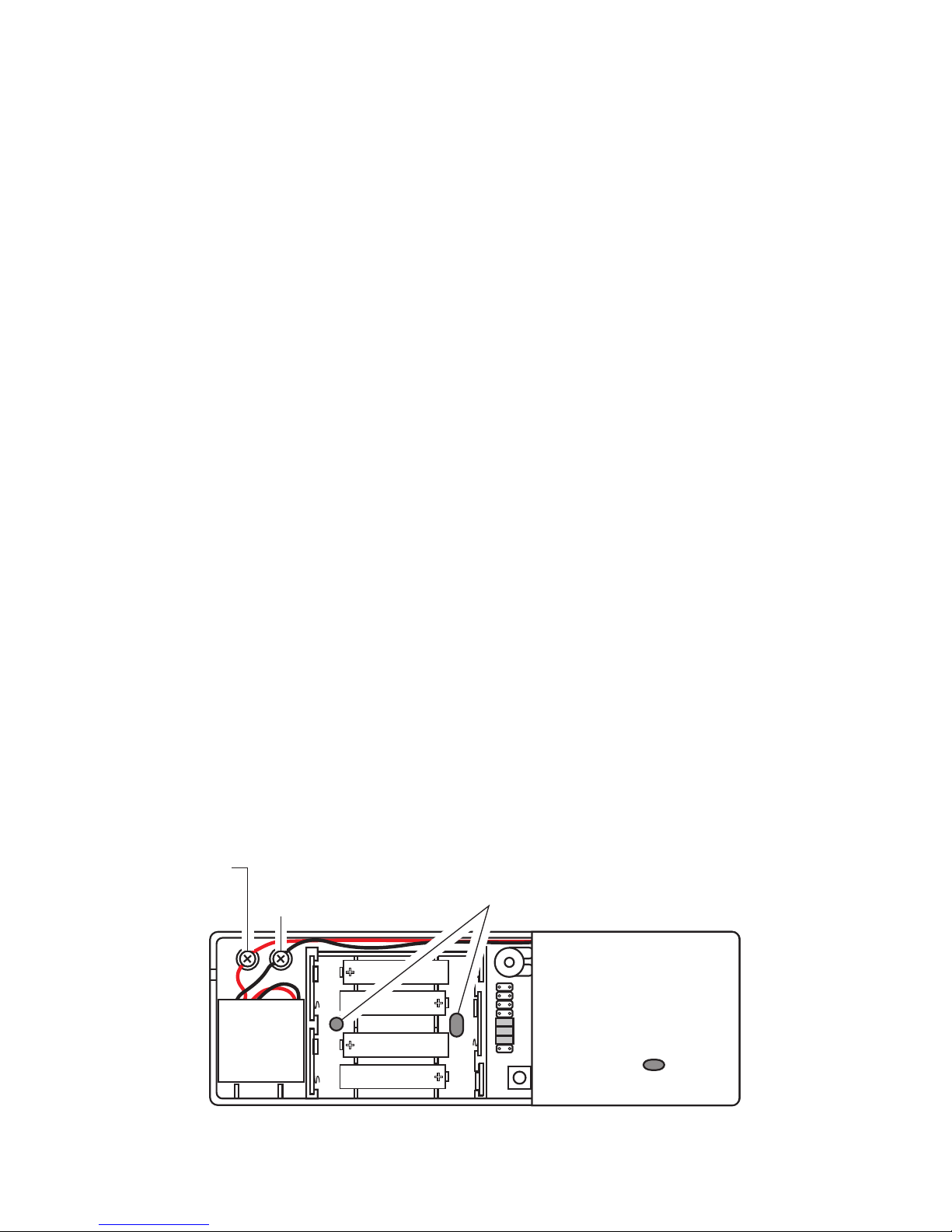
Test
Button
Microphone
Sensitivity
Adjustment
Microphone
WireTerminals
Figure 3
Removable
Microphone
Wire
Routing
Slot
-3-
598-1070-04
• Removemicrophonefromchimeextenderandmountmicrophonedirectly
toexistingchimecaseorinsideexistingchime.Note: Do not mount mi-
crophonetochimebars.
– Gentlyprymicrophoneoutofchimeextendercase(seeFigure3).
– Routemicrophonewiresthroughsmallslotinchimeextendercase.Note:
Ifnecessary,removemicrophonewiresfromwireterminalsusingasmall
phillipsscrewdriver.Afterroutingwiresasneeded,reattachcolor-coded
wirestomatchingwireterminals(seeFigure5).
– Usedouble-sidedtape(included)toattachthemicrophonetotheexisting
chimecase.Note: Make sure the small hole in the microphone is facing
awayfromtape.
Whenthechimeextenderandthewirelesschimeare
workingcorrectly,adjustthemicrophonesensitivitytotheleastsensitive
positiontoreliablyactivatethechimeextender.Ifsensitivityissettoohigh,
commonhouseholdnoisesmayactivatethechimeextender.
4. Mount chime extender.Useeitherscrewsordoublesidedtapetomount
chimeextender.
• Screw Mounting
– Tomountwithscrews,removebatterycoverbypressingoncoverwith
yourthumbandslidingcoveroff(seeFigure2).
– Temporarilyremovethebatteries.
– Holdthechimeextenderinthedesiredlocation,andmarkthetwomounting
holes(seeFigure5).
– Drilltwo7/32"diameterpilotholesforwallanchors(provided)andinsert
anchors.
– Insert2screws(provided)throughholesinbackofchimeextenderand
tightensecurely.
– Replacebatteriesandbatterycover.
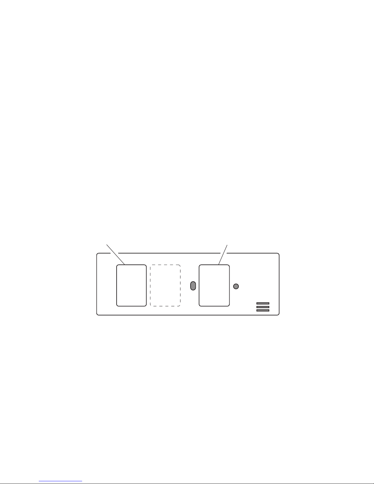
MountingHoles
Figure 5
Continued
RedWireTerminal
BlackWireTerminal
-4- 598-1070-04
Double-SidedTape
Figure 6
• Tape Mounting:Whenattachingchimeextenderusingdoublesidedtape,
makesurethesurfaceofthewallisclean.
– Installbatterycover.
– Peeltheprotectivebackingfromonesideoftwopiecesofthedouble-
sided tape and apply the tape to the areas on the back of the chime
extenderasshowninFigure6.
– Remove the remaining protective backing and carefully stick the chime
extenderinthedesiredlocation.
5. Adjust volume control (Available on selected chimes). Unplug chime and
adjustvolumecontroltodesiredvolume(seeFigure1).Plugchimebackinto
walloutlet.
Double-SidedTape

-5-
598-1070-04
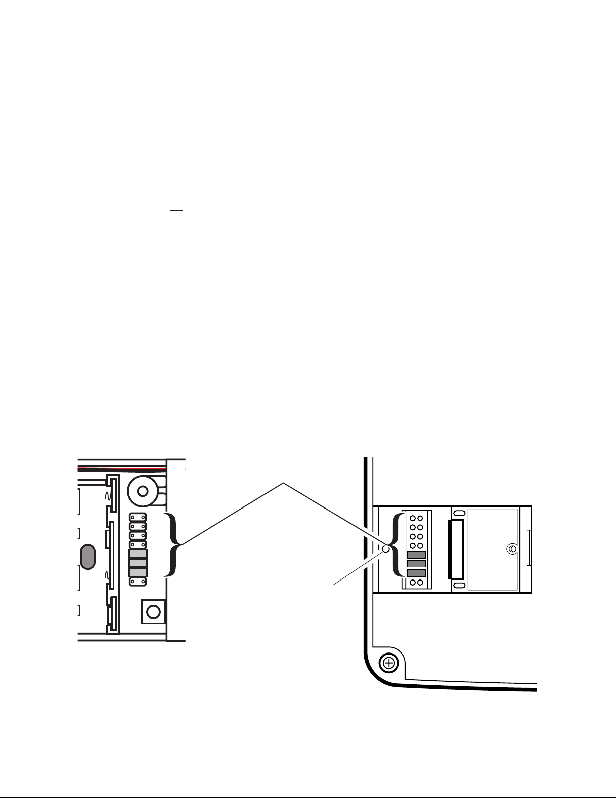
12345678
12345678
Inside
Chime
Extender
Remove
screwtoopen
access door
BackofChime
Tune Setting
Tune Setting (Not used
on all models)
Note:Somemodelsmightrequiretheuseoftweezers
toremoveandreplacethejumpers.
Yourwirelesschimehasdifferentselectabletunes:Ding (one note), Ding-Dong
(twonote),orWestminster(eightnote)(Availableonselectedchimes).The
factorysettingisfortheDing-Dongtune(orWestminster,whenavailable).This
tunecanbechangedbyfollowingtheinstructionsbelow.
• Ding (one note tune)
InsideChimeExtender:Addajumpertolocation8.
• Ding-Dong(twonotetune)
InsideChimeExtender:Removejumperfromlocation8.
Chime:Removejumperfromlocation8.
• Westminster(Eightnotetune)(Availableonselectedchimes)
InsideChimeExtender:Removejumperfromlocation8.
Chime:Addajumpertolocation8.
Note:Allmodelshavebothfrontandbackdoortunecapabilities.Werecom-
mend the back door use the Ding tune and the front door use the Ding-Dong
tune (or Westminstertune,availableonselectedchimes).Youmaypurchase
anyACE®wirelesspushbuttonforasecondentrance.
Figure 7
reconnecting to power.
Tune Settings

-6- 598-1070-04
Troubleshooting
A. Chime does not sound:
• Redlightonthechimeextenderdoesnotlight.
– Checkorientationofchimeextenderbatteries(Seediagraminsidechime
extenderforcorrectbatteryorientation.)
– Checkchargeofchimeextenderbatteries,replaceifnecessary.
• Redlightonthechimeextenderdoeslight.
–
Makesurechimeextenderandchimecodesarethesame(seeFigure8).
– Makesuretheplug-inchimehaspowergoingtoit.
Chimeextenderandexistingchimearesettothesamecode;changethe
code setting for the chime extender set (see Code Settingbelow).
Chimeisreceivinginterferencefromanotherwirelessdevice;changethe
code setting (see Code Settingbelow).
The chime extender has special circuitry to reduce false triggers from most
commonhouseholdnoises.Thechimeextenderisdesignedtooptimizeits
responsetomid-frequencysoundwheremostmechanicaldoorbellsoperate
andtominimizeresponsetoextremelyloworhighfrequencysounds.Also,
thedesiredsoundmustbepresentcontinuouslyforatleast2seconds.
This design reduces the response to door slams, vibration, normal music
andtalking,etc.Loudcontinuousnoisessuchasyellingchildrenorvery
loudmusicmaycausefalsetriggering.Whenoperatinginalocationwith
unusuallyhighambientnoiselevelstrytheremediesbelow.
–
Turnthemicrophonesensitivityknobcounterclockwisetoreducesensitivity.
– Attach chime extender microphone directly to the existing chime case
neartheringingpart(butnotonit)oftheexistingchime.
• Do not mount thechime extender on metal or near metalstuds.This
reducesthechimeextenderrange.Use1/4"to1/2"(6to13mm)wood
shimstomovethechimeextenderoffthemetalsurface.
• Concreteoorsmayreducerange.Movechimeawayfromoor.
•Attachchimeextendermicrophonedirectlytotheexistingchimecasenear
theringingpart(butnotonit)oftheexistingchime.
• Trylocatingchimeclosertochimeextender.
E. Code Setting:
reconnecting to power.
Itisrecommendedtoonlychangeonecodepositionatatimeandthencheck
toseeifsystemisfunctioningproperly.
-7-
598-1070-04
12345678
1. Unplugchimefrompowersource.
2. Openthecasesandlocatethejumpersonboththechimeextenderand
chime(seeFigure8).
3. Thechimeextenderandchimebothhaveeightdifferentjumperlocations.
Jumperpositions1through7areusedforsettingthecode.
4. Tochangethecode,either:
• Addajumpertothesamelocationonboththechimeextenderandthe
chime or...
• Removeajumperfromthesamelocationonboththechimeextenderand
the chime or...
• Moveajumperonthechimeextenderfromonelocationtoanother.Move
thecorrespondingjumperonthechimetomatchthenewlocationinthe
chimeextender.
Example:Movejumperatlocation“5”tolocation“4”onboththechime
extenderandthechime.
Note:
Note:Unitwillcomefactorysetwithjumpersinlocations5,6,and7onthe
chimeextenderandonthechime.
The range of the wireless chime canvary withlocation, temperature,and
batterycondition.
InsideChime
Extender
BackofChime
Note: Some models might require
the use of tweezersto remove
andreplacethejumpers. Figure 8
12345678
*CodeSettings
1-7MustMatchBoth
SensorandChime
Remove
screwtoopen
access door

-8- 598-1070-04
Technical Service
Ifyouexperienceaproblem,followthisguide.Youmayalsowanttovisitour
Websiteat:www.hzsupport.com.Iftheproblempersists,call*forassistance
at 7:30AMto4:30PMCST(M-F).Youmayalsowrite*to:
HeathCoLLC
P.O.Box90045
BowlingGreen,KY42102-9045
ATTN: Technical Service
*IfcontactingTechnicalService,pleasehavethefollowinginformationavailable:
ModelNumber,DateofPurchase,andPlaceofPurchase.
requests.
ThisdevicecomplieswithPart15oftheFCCRulesandRSS-210ofIndustry
Canada.Operationissubjecttothefollowingtwoconditions:(1)thisdevicemay
not cause harmful interference, and (2) this device must accept any interference
received,includinginterferencethatmaycauseundesiredoperation.
Theuseriscautionedthatchangesormodicationsnotexpresslyapprovedby
the party responsible for regulatory compliance could void the user’s authority
tooperatetheequipment.

-9-
598-1070-04
ACE®reservestherighttodiscontinueandtochangespecicationsatanytime
withoutnoticewithoutincurringanyobligationtoincorporatenewfeaturesin
previouslysoldproducts.
FIVE YEAR LIMITED WARRANTY
Thisisa“LimitedWarranty”whichgivesyouspeciclegalrights.You
mayalsohaveotherrightswhichvaryfromstatetostateorprovince
toprovince.
Foraperiodofveyearsfromthedateofpurchase,anymalfunction
causedbyfactorydefectivepartsorworkmanshipwillbecorrectedat
nochargetoyou.
Not Covered -Repairservice,adjustmentandcalibrationduetomisuse,
abuse or negligence, light bulbs, batteries, and other expendable items
arenotcoveredbythiswarranty.Unauthorizedserviceormodicationof
theproductorofanyfurnishedcomponentwillvoidthiswarrantyinits
entirety.Thiswarrantydoesnotincludereimbursementforinconvenience,
installation, setup time, loss of use, unauthorized service, or return ship-
pingcharges.
ThiswarrantycoversonlyACE®assembled products and is not extended
tootherequipmentandcomponentsthatacustomerusesinconjunction
withourproducts.
THISWARRANTYISEXPRESSLYINLIEUOFALLOTHERWARRAN-
TIES,EXPRESSORIMPLIED,INCLUDINGANYWARRANTY,REPRE-
SENTATIONORCONDITIONOFMERCHANTABILITYORTHATTHE
PRODUCTSAREFITFORANYPARTICULARPURPOSEORUSE,AND
SPECIFICALLYINLIEUOFALLSPECIAL,INDIRECT,INCIDENTAL,OR
CONSEQUENTIALDAMAGES.
REPAIRORREPLACEMENTSHALLBETHESOLEREMEDYOFTHE
CUSTOMERANDTHERESHALLBENOLIABILITYONTHEPARTOF
ACE®FORANYSPECIAL,INDIRECT,INCIDENTAL,ORCONSEQUEN-
TIALDAMAGES,INCLUDINGBUTNOTLIMITEDTOANYLOSSOF
BUSINESSORPROFITS,WHETHERORNOTFORESEEABLE.Some
statesorprovincesdonotallowtheexclusionorlimitationofincidental
or consequential damages, so the above limitation or exclusion may not
applytoyou.
requests.

-10- 598-1070-04
Extensor de
campana
©2008 598-1070-04S
Modelo 6157
Estepaquetetiene(Elestilodelacampanay
del prolongador de la campana puede variar de
la ilustración):
• CampanaEnchufableInalámbrica
• Extensordecampana
• Paquetedeferretería
El prolongador de la campana requiere 4
baterías alcalinas “AAA” (no incluidas).
SuextensordecampanaACE®le permite aumen-
tar la cobertura del timbre de puerta a cualquier
cuartodesucasasinnecesidaddeinstalarmás
cables.Elextensordecampana“escucha”cuando
el timbre de puerta suena y luego transmite una
señal con frecuencia de radio a la unidad de
campanaenchufableen otrapartedelacasa.
Nota:Elprolongadordelacampananopuede
diferenciar entre los tonos de la puerta frontal y
ladeatrásdesucampanaexistente.
Figura 1
Puertadeaccesoalpuente(Vea
laseccióndeTonosoCódigos)
ADVERTENCIA: Para prevenir una
posible LESIÓN SERIA o LA MUERTE:
las baterías.
-
diatamente al doctor.
1.
Para
reducir el riesgo de choque eléctrico, este
equipo tiene un enchufe polarizado (una
patillaesmásanchaquela otra).Esteen-
chufe podrá insertarse en un tomacorriente
polarizado solamente deunamanera. Si el
mismo no entra completamente en el tomaco-
rriente,inviertaelenchufe.Siaúnnoencaja
completamente, póngase en contacto con un
electrista competente para qua éste instale el
tomacorrientecorrecto.Notratedesuprimir
estacaracterísticadeseguridad.
ControldelVolumen
delaCampana
(Campanas
seleccionadas)
-11-
598-1070-04
Campana
existente
Extensordecampana Luz de la transmisión
Figura 4
12345678
Figura 2
2. Abra la caja del prolongador de la campana.
Presione la tapa con el pulgar y retire la campana
deslizándolacomoseindicaenlaFigura2.
3. Ponga las 4 baterías alcalinas “AAA” (no inclui-
das).Veaeneldiagramainteriordelprolongadorde
lacampanalaposicióncorrectadelasbaterías.
Instalación
Nota:Elprolongadordelacampanapuedecolocarse
horizontaloverticalmente.
1.
Pruebe el alcance.Coloquetemporalmenteelpro-
longador de la campana cerca de la campana existen-
te.Presioneelbotón“test”delinteriordelprolongador
delacampanaparavericarquetantolacampana
comoelprolongadorfuncionencorrectamente.Sila
campana no suena, vea Análisis de Averías.
Conelprolongadordela
campanaaúnenelsitiodeseado,activelacampana
existente de la puerta.Silacampananosuena,
pruebeunoomásdelossiguientespasos.
• Girelaperilla de regulación de la sensibilidad
del micrófono en sentido horario para aumentar
lasensibilidad(vealaFigura3).
Botón de
prueba
Ajustedela
sensibilidad
del micrófono
Terminales
para el alambre
del micrófono
Micrófono
removible
Figura 3
Ranura
guíadel
alambre
Continúa
-12- 598-1070-04
• Vuelaacolocartemporalmenteelprolongadordelacampanaalrededor
delacampanaexistente.
• Retireelmicrófonodelprolongadordelacampanaycolóquelodirectamen-
teenlacajadelacampanaexistenteodentrodelacampanaexistente.
Nota:Nocoloqueelmicrófonoenlasbarrasdelacampana.
– Retireelmicrófonofueradelacajadelprolongadordelacampana
haciendopalancahaciafueraconcuidado(vealaFigura3).
– Paselosconductoresdelmicrófonoporlapequeñaranuradelacajadel
prolongadordelacampana.Nota: Si es necesario, retire los conductores
delmicrófonodelosterminalesconundestornilladorPhillipspequeño.
Luego de pasar los conductores por donde es necesario, vuelva a
conectarlosconductorescodicadosconcoloresemparejándoloscon
losterminales(vealaFigura5).
– Conlacintaengomadaporlosdoslados(incluida)sujeteelmicrófono
alacajadelacampanaexistente.Nota:Asegúresequeelpequeño
oriciodelmicrófonoestéorientadohaciafueradelacinta.
3. Regule la sensibilidad.Cuandoelprolongadordelacampanaylacampana
inalámbricafuncionencorrectamente,regulelasensibilidaddelmicrófonoa
la posición menos sensible para que el prolongador de la campana se active
sinfallos.Siseponelasensibilidaddemasiadoalta,losruidoscomunesde
lacasapuedenactivaralprolongadordelacampana.
4. Coloque el prolongador de la campana. Utilice los tornillos o la cinta
engomadaporlosdosladosparacolocarelprolongadordelacampana.
• Montaje del tornillo
– Paracolocarconlostornillos,retirelatapadelabateríahaciendopresión
conelpulgarenlatapaparadeslizarlayquitarla(vealaFigura2).
– Quitelaspilastemporalmente.
– Sostenga el prolongador de la campana en el sitio deseado, y marque
losdosoriciosdemontaje(vealaFigura5).
Agujerosdemontaje
Figura 5
Terminal del
conductorrojo Terminal del
conductor negro
-13-
598-1070-04
Cintadedoblelado
Figura 6
– Taladreunoricioguíade5.5mm(7/32pulgadas)dediámetropara
las2anclasdepared(provistas)einsertelasanclas.
– Inserte losdostornillos (provistos) porlosoricios posteriores del
prolongadordelacampanayaprietebien.
– Vuelvaacolocarlasbateríasconsutapa.
• Montaje con cinta adhesiva:Cuandosujeteelprolongadordelacampana
conlacintaengomadaporlosdoslados,asegúresequelasuperciede
laparedestélimpia.
– Coloquelatapadelabatería.
– Quitelacapaprotectoradeunacaradelasdostirasdelacintaen-
gomada por los dos lados, y aplique la cinta a la parte posterior del
prolongadordelacampanacomoseindicaenlaFigura6.
– Retire la otra capa protectora y pegue con cuidado el prolongador de
lacampanaenelsitiodeseado.
5. Ajuste del control del volumen (Disponible en los timbres selecciona-
dos).Desenchufelacampanayajusteelcontroldelvolumenalvolumen
deseado(vealaFigura1).Enchufedenuevolacampanaeneltomacorriente
delapared.
Cintadedoblelado

-14- 598-1070-04
12345678
Programación del tono (No
se usa en todos los modelos)
Quiteel
tornillo para
abrir la puerta
de acceso
12345678
Interiordel
prolongador de
la campana
Figura 7
Partedeatrás
de la campana
Programación
del tono
Nota:Algunos modelos podríanrequerir elusode
pinzasespecialespararetirarycolocarlospuentes.
Sucampanainalámbricatienetonosdiferentesquepuedenseleccionarse:Tilín
(una nota), Tilín-Talán (dos notas), o Westminster (ocho notas) (Disponible
enlostimbresseleccionados).LacalibracióndefábricaeseltonoTilín-talán
(oeltonoWestminstercuandoestádisponible).Estetonopuedesercambiado
siguiendolasinstruccionesquesiguen.
• Tilín (tono de una nota)
Interiordelprolongadordelacampana:aumenteunpuentealsitio8.
• Tilín-talán (tono de dos notas)
Interiordelprolongadordelacampana:Quiteelpuentedelsitio8.
Campana:Quiteelpuentedelsitio8.
• Westminster (tono de ocho notas) (Disponible en los timbres seleccionados)
Interiordelprolongadordelacampana:Quiteelpuentedelsitio8.
Campana:Aumenteunpuentealsitio8.
Nota: Todas las campanas tienen capacidad de tonos para las puertas frontal y
posterior.RecomendamosquelapuertaposterioruseeltonoTilín y la puerta
frontal el tono Tilín-Talán (o el tono Westminster, disponible en los timbres
seleccionados).UstedpuedecomprarcualquierpulsadorACE®inalámbrico
paraunasegundapuertadeentrada.
Programación del tono
de alimentación antes de abrir la puerta de acceso de códigos. Cierre

-15-
598-1070-04
Análisis de Averías
A. La campana no suena:
• Laluzrojadelprolongadordelacampananoenciende.
– Reviselaposicióndelasbateríadelprolongadordelacampana(Veaenel
esquemainteriordelprolongadordelacampanalaposicióncorrecta).
– Reviselacargadelasbateríasdelprolongadordelacampana.Cám-
bielassiesnecesario.
• Laluzrojadelprolongadordelacampananoenciende.
– Asegúresequeloscódigosdelprolongadory delacampanasean
iguales
(
vealaFigura8
)
.
– Asegúresequelaenergíavayaalacampanaenchufable.
suena continuamente:
• Elprolongadordelacampanaylacampanaexistenteestánpuestoscon
elmismocódigo.Cambielacalibracióndelcódigodelprolongadordela
campana(veaabajolaConfiguración de Códigos).
Lacampanaestárecibiendointerferenciadeotrodispositivoinalámbrico;
cambieloscódigos(veaabajolaConfiguración de Códigos).
• Elprolongadordelacampanatieneuncircuito especial parareducir
activacionesfalsasdebidasalamayoríaderuidoscomunesdelacasa.
Elprolongadordelacampanaestádiseñadoparaoptimizarsurespuesta
asonidosdemedia–frecuenciadondefuncionanlamayoríadetimbres
mecánicosyparaminimizarlarepuestaasonidosdefrecuenciasextre-
madamentealtasobajas.
Además,elsonidodeseadodebesercontinuo
porlomenospor2segundo.Estediseñoreducelarespuestaalospor-
tazos,alamúsicanormalyalasconversaciones,etc.Losruidosaltos
continuos,talescomogritosdeniñosomúsicamuyalta,puedenhacer
quelacampanasuene.Cuandotrabajeentaleslugaresconnivelesde
ruidomuyaltostratelassiguientessoluciones.
– Gire la perilla de sensibilidad del micrófono en sentido antihorario para
reducirlasensibilidad.
– Sujeteelmicrófono delprolongador dela campanadirectamentea
lacajadelacampanaexistentecercadelapartesonorade(perono
sobre)lacampanaexistente.
instalada:
• Nomonteelprolongadordelacampanasobremetalocercadeespá-
rragosmetálicos.Estoreduceelalcancedelprolongadordelacampana.
Usecuñasdemaderade6a13mm(1/4a1/2pulgada)parasepararel
prolongadordelacampanadelasuperciemetálica.
Continúa
-16- 598-1070-04
Se recomienda cambiar tan sólo un puente por vez y luego comprobar si el
sistemafuncionacorrectamente.
1. Desenchufelacampanadelafuentedealimentación.
2. Abralascajasycoloquelospuentesenelprolongadordelacampanayen
lacampana(vealaFigura8).
3. Elprolongadorylacampanatienenambosochositiosparalospuentes.Las
posicionesdepuentedel1al7seusanparaprogramarelcódigo.
4. Paracambiarelcódigo,o:
• Añadaunpuenteenelmismositiotantoenelprolongadorcomoenla
campana, o...
• Retireunpuentedelmismo sitio tanto en el prolongadorcomoenla
campana, o...
• Muevaunpuentedelprolongadordelacampanadeunsitioaotro.Mueva
el puente correspondiente de la campana para que coincida con la nueva
ubicacióndelpuentedelprolongador.
Ejemplo:Muevaelpuentedelaposición“5”alaposición“4”tantoenel
prolongadorcomoenlacampana.
de alimentación antes de abrir la puerta de acceso de códigos. Cierre
• Lospisosdeconcretopuedenreducirelalcance.Muevalacampanafuera
delpiso.
• Sujeteelmicrófonodelprolongadordela campanadirectamenteala
cajadecampanaexistentecercadelapartesonorade(peronosobre)
lacampanaexistente.
• Tratedecolocarlacampanacercaalprolongadordelacampana.
E. Programaciones del código:

-17-
598-1070-04
Interiordel
prolongador de
la campana
Partedeatrás
de la campana
Figura 8
*Losajustesdecódigodel
1al7debenserigualesen
el detector y en la campana
Quiteeltornillo
para abrir la puerta
de acceso
12345678
12345678
Nota:Algunos modelospodrían
requerir el uso de pinzas especiales
pararetirarycolocarlospuentes.
Nota: Los puentes de las posiciones 1 a la 7 deben estar exactamente
igual tanto en el prolongador como en la campana para que este sistema
Nota:Launidadvienedefábricaconlospuentespuestosenlasposiciones5,
6,7tantoenelprolongadorcomoenlacampana.
Elalcancedelacampanainalámbricapuedevariarcon:laubicación,tempe-
raturaycondicionesdelabatería.

-18- 598-1070-04
Sitienealgúnproblema,sigaestaguía.Ustedpuedetambiénvisitarnuestro
sitioWeb:www.hzsupport.com.Sielproblemacontinúa,llameal1-800-858-
8501(sóloparahablareninglés),de7:30AMa4:30PMCST(L-V).Usted
puede también escribir a:
HeathCoLLC
P.O.Box90045
BowlingGreen,KY42102-9045
ATTN: Technical Service (Servicio Técnic)
* Si se llama al Servicio Técnico, por favor tener lista la siguiente información:
NúmerodeModelo,FechadecomprayLugardecompra.
solicitud de garantía.
EsteaparatocumpleconlaParte15delasReglasdelaFCC(ComisiónFe-
deraldeComunicaciones)yconlaRSS-210delasIndustriasdelCanadá.El
funcionamientoestásujetoalasdossiguientescondiciones:(1)esteaparato
no puede causar interferencias dañinas, y (2) este aparato debe aceptar cual-
quier interferencia recibida, incluyendo una interferencia que pueda causar un
funcionamientoindeseable.
Seadviertealusuarioquecambiosomodicacionesnoaprobadasexpresa-
menteporlaparteresponsabledecumplirconlosreglamentospodríainvalidar
laautoridaddelusuarioparaelusodeesteequipo.

-19-
598-1070-04
ACE®sereservaelderechodedescontinuarydecambiarlasespecicacio-
nes a cualquier momento, sin previo aviso, sin incurrir en ninguna obligación
detenerqueincorporarnuevascaracterísticas en los productos vendidos
anteriormente.
GARANTÍA LIMITADA A 5 AÑOS
Estaesuna“GarantíaLimitada”queledaaUd.derechoslegalesespe-
cícos.Ustedpuedetambiéntenerotrosderechosquevaríandeestado
aestadoodeprovinciaaprovincia.
Porunperíodode5añosdesdelafechadecompra,cualquiermalfun-
cionamientoocasionadoporpartesdefectuosasdefábricaomanode
obraserácorregidosincargoparaUd.
No cubierto -Serviciodereparación,ajusteycalibracióndebidoalmal
uso,abusoonegligencia,bombillas,baterías,uotraspartesfungibles
noestáncubiertas por estagarantía. Los Serviciosnoautorizados o
modicacionesdelproductoodecualquiercomponentequeseprovee
invalidaránestagarantíaensutotalidad.Estagarantíanoincluyereem-
bolso por inconveniencia, instalación, tiempo de instalación, perdida de
uso,servicionoautorizado,ocostosdetransportederetorno.
EstagarantíacubresolamentelosproductosensambladosporACE®y
no se extiende a otros equipos o componentes que el consumidor usa
juntoconnuestrosproductos.
ESTAGARANTÍAESTÁEXPRESAMENTEENLUGARDEOTRAS
GARANTÍAS,EXPRESADASOSOBREENTENDIDAS,INCLUYENDO
CUALQUIERGARANTÍA,REPRESENTACIÓNOCONDICIÓNDECO-
MERCIABILIDADOQUELOSPRODUCTOSSEADAPTENPARACUAL-
QUIERPROPÓSITOOUSOENPARTICULAR,YESPECIFICAMENTE
ENLUGARDETODOS LOS DAÑOS ESPECIALES,INDIRECTOS,
INCIDENTALESYCONSECUENTES.
LAREPARACIÓNOELREEMPLAZODEBERÍASERLAÚNICASOLU-
CIÓNDELCLIENTEYNOHABRÁRESPONSABILIDADPORPARTEDE
ACE®PORCUALQUIERDAÑOESPECIAL,INDIRECTO,INCIDENTAL
OCONSECUENTE,INCLUIDOSPERONOLIMITADOSACUALQUIER
PÉRDIDADENEGOCIOOGANACIAS SEAN O NO PREVISIBLES.
Algunos estados o provincias no permiten la exclusión o limitación de
daños incidentales o consecuentes, de modo que la limitación o exclusión
arribaindicadapuedequenoseapliqueaUd.
cualquier solicitud de garantía.
-20- 598-1070-04
Prolongateur de
carillon
©2008 598-1070-04F
Modèle 6157
Cetemballagecontient(Lemodèledumodule
d’extensionetducarillonpeutvarierdumodèle
illustré):
• Carillonenchable,sansl
• Prolongateurdecarillon
• unensembledeferrures
Le module d’extension exige 4 piles « AAA »
alcalines (non comprises).
VotreprolongateurdecarillonACE®vous permet
d’étendre la couverture de tout carillon de porte
àtoutepiècedelamaisonsansajoutdels.Le
prolongateur de carillon « écoute » votre sonnerie
de porte existante, puis transmet un signal radio
aucarillonenchablequisetrouveailleursdans
lamaison.Note : Le module d’extension ne peut
faire la différence entre la tonalité de l’entrée
principale et celle de l’entrée secondaire du
carillonenplace.
Figure 1
Portillond’accèsaux
commutateurs (voir la
sectionTonalitésouCodes)
Pour réduire
le risque de choc électrique, cet appareil est
dotéd'unechepolarisée(unlamepluslarge
quel'autre).Cettechepeutêtreinséréedans
uneprised'uneseulefaçonseulement.Sila
chenepeutêtreinséréeàfonddanslaprise,
inversez-la.Sielleneconvienttoujourspas,
demandez à un électricien compétent d'ins-
tallerunepriseappropriée.Netentezpasde
contournercettefonctiondesécurité.
de DÉCÈS :
des piles.
Commandede
volume du carillon
(carillons
sélectionnés)
Table of contents
Languages:
Other Heath Zenith Extender manuals


