Heathkit Heathkit HD-1234 User manual


HEATHCOMPANYPHONEDIRECTORY
The
foilomna telephone
numbers
are
aired lines lo
the
depanmem lirted:
Kit
orders
and
delW
inlormation
......................
(616) 9825411
Cle4n
............................................
(616) 8823661
Replacemem
Pam..
...............................
(616) 982.3~1
TBChhicd
Assistance
RC,
Aud'b,
and
E&onic
hgans .................
(616) 982.3310
hateur
Radio
...................................
(616) 882-3286
Test Equipment.
Slmbe
Lighfs,
Cdcuiatoro,
CIOC~,
Weather
In8humenlP
........................
(616) 982.3315
Television
........................................
(616) 982-3307
Aubmme,
Mame.
Wliances,
SBardty.
&nerd
Prduck..
........................
(515) 9825496
YOUR
HEATHKIT
90-DAY
FULL
WARRANTY

Assembly
and
Operation
of
the
COAXIAL SWITCH
MODEL
HD-1234
TABLE OF CONTENl'S
Introduction
.............................
1
Parts List
...............................
2
Step-by-stepAssembly
.........................
4
Installationand Applications
......................
9
.........................
In Case of Difficulty
13
Specifications
.............................
14
Warranty
........................
Inside front cover
Customer Service
.....................
Insiderear cover
INTRODUCTION
The Model HD-1234 Coaxial Switch
is
designed to switch one RF source or
receiver to any one of severalantennas or RF loads, while grounding the unused
connectors.
The Coaxial Switch can be used in conjunction with the Heathkit RF Load
Wattmeter for off-theair tuneup, and can then be immediately switched to an
antenna for normal transmissionand reception.
A
mounting bracket is provided to permit you to conveniently hangthe switch
on the side of an equipment enclosure, onto a desk, or on a wall. The switch
may be used handily without the mounting bracket in any application which
suitsthe needs of your transmission system.
HEATH
COMPANY
BENTON
HARBOR. MICHIGAN
49022

Page 2
KEY PART PARTS
No. No. Per Kit
--
-
METAL PARTS
HARDWARE
PARTS
LIST
Unpack all the parts inthe kitand check each part against the following list. The
key numberscorrespond tonumbers onthe Parts Pictorial.
DESCRIPTION PRICE
Each
-
Connector panel .25
Ground panel .45
Mounting bracket .90
Cover plate .70
4-40x 114" self- .05
tapping screw
4-40x 114" flat .05
headscrew
6-32x 112" screw .05
#6 x 518" sheet metal .05
screw
6-32nut .05
Thumbnut .05
Control nut
.05
#6
flat washer .05
Control flat washer .05
Control lockwasher .05
#6 lockwasher .05
#6 solder lug .05
8-32x 318" setscrew .05
KEY PART PARTS DESCRIPTION PRICE
No. No.
--
Per Kit
-
Each
-
MISCELLANEOUS
C1 63-683 1 Rotary switch 4 30
C2
436-5 5 Coaxial jack .85
C3
462-24 1 Knob .30
390-1023 1 Labelset .40
(24
391-34 1 Blueand white label .15
597-260 1 Parts Order Form
597-308 1 KitBuilders Guide
1
Manual (See front cover 2.00
for part number.)
Solder (Add~t~onal
3'
rolls
of solder, #331-6, can be
ordered for 25 cents each.)
The above prices apply only on purchases from the Heath Company where
shipment is to a U.S.A. destination. Add 10% (minimum 25 cents) tothe prlce
when ordering from a Heathkit Electronic Center to cover local sales tax,
postage, and handling. Outside the U.S.A., parts and service are available from
your local Heathkit source and will reflect additional transportation, taxes,
duties, and rates of exchange.

Page
3
PARTS PICTORIAL

Page 4
STEP-BY-STEP ASSEMBLY
Before you start toassemblethis kit, read the "Kit Builders Guide" for complete
( )
Install a 6-32
x
112" screw and a #6 solder lug through theground panel
informationon soldering and step-by-stepassembly procedures. as shown. Secure the screw with a #6 lockwasherand a 6-32 nut. Position
the solder lug straight up toward the edge of the panel with the panel
Position all parts as shown in the Pictorials. Follow the instructions carefully, flange tothe left.
and readthe entire step before you performthe operation.
(
)
Place two
#6
flat washers and a thumbnut on screw. Turn the thurnbnut
Solder
a
part or agroup of partsonly when instructedtodoso. finger tight.
NOTE
:
When you use self-tapping screws inthis kit, as inthe following step,
do
Refer to Pictorial
1
for the following steps. notovertighten the screws. This
can
strip the threads inthe metal parts.
( )
Mount a coaxial jack on a connector panel
4-40
x
114"
self-tapping screws. Position the open portionof
SELF
TAPPING
toward either side of the panel.
#6
FLAT
WASHERS
with four 4-40
x
114"
the connector solder post
SCREW
PICTORIAL
1

Page
5
(
)
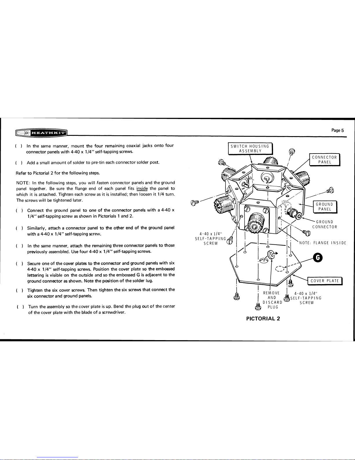
In the same manner, mount the four remaining coaxial jacks onto four
connector panelswith 4-40 x 114'' self-tapping screws.
(
)
Add a small amount of solder to pre-tineach connector solder post.
Refer to Pictorial
2
for the following steps.
NOTE:
In the following steps, you will .fastenconnector panels and the ground
panel together. Be sure the flange end of each panel fits wethe panel to
which it is attached. Tighten each screw as it is installed; then loosen it 114 turn.
The screws will be tightened later.
(
)
Connect the ground panel to one of the connector panels with a 4-40 x
114" self-tapping screw as shown in Pictorials
1
and
2.
(
)
Similarly, attach a connector panel to the other end of the ground panel
CONNEClOR
with
a
4-40 x 114" self-tapping screw.
SELF-TAPPING
( )
In the same manner, attach the remaining three connector panels tothose
NOTE. FLANGE
IhSI
DE
previously assembled. Use four 4-40x 1/4" self-tapping screws.
(
)
Secure one of the cover plates to the connector and ground panels with six
4-40 x 114" self-tapping screws. Position the cover plate so the embossed
lettering is visible on the outside and so the embossed
G
is adjacent tothe
ground connector as shown. Notethe positionof thesolder lug.
( )
Tighten the six cover screws. Then tighten the six screws that connect the
six connector and groundpanels.
( )
Turn the assembly so the cover plate is up. Bend the plug out of the center
of the cover plate with the blade of ascrewdriver.
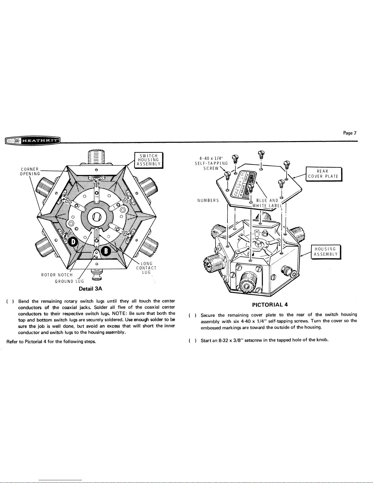
PICTORIAL
2

Page 6
Refer to Detail
3A
andtoPictorial
3
for thefollowing steps.
LOCKWASHER
UND
CONNECTOR
0
FLAT WASHER
6
PICTORIAL
3
NOTE:
Carefully study the rear of the rotary switch
as
shown inDetail
3A.
Note
that there is one long contact lug on the switch wafer at
B,
and also there is a
notch inthe rotary center portionof the switch.
(
)
Grasp the switch shaft with a pair of pliers and turnthe switch rotor until
the long contact lug and the rotor notch are positionedtogether as shown
in the Detail. Do not turn the rotor again until the knobhas been secured
tothe switch shaft.
(
)
Carefully bend each of the lugs so
it
is flat and straight out from the
surface.
(
)
Refer to the Pictorial and carefully insert the rotary switch intotheswitch
housing assembly; the switch lug will easily drop through the corner
openings in the assembly. Rotate theswitch and positionthe longcontact
lug nearthe ground luginside the housingas shown.
(
)
Place the control flat washer and the control nut on the switch shaft; do
nottighten the nut.
(
)
Reach inside the housing and turn the body of the switch until the long
contact lug is directly under the ground lug as shown in Detail
3A
Note
that one single lug on the front of the switch wafer will be under the
connector center conductor at
D.
The remaining pairs of switch lugs will
be in a position above and below each of the remaining four connector
center conductors.
(
)
Holdthe switch firmly inthis position and tighten thecontrol nut.
(
)
Bend the ground lug downward with the blade of a screwdriver until
it
touchesthe longswitch lug. Solder the two lugstogether.

Page
7
re*:w---=*-
GROUND
i'6~
Detail
3A
(
I
Bend the remaining rotary switch lugs until they all touch the center
conductors of the coaxial jacks. Solder all five of the coaxial center
PICTORIAL
4
conductors to their respective switch lugs. NOTE: Be sure that both the
(
,
Secure
the
remaining
cover
plate
to
the
rear
of
the
switch
housing
top and bottom switch lugsare securely soldered. Use enough solder to
be
assembly with six 4-40 x
114''
self-tapping screws. Turn the cover so the
sure the job is well done, but avoid an excess that will short the inner embossed markingsare toward the outside of the housing.
conductor and switch lugs tothe housing assembly.
Refer to Pictorial
4
for the followingsteps.
( )
Start an
8-32
x
318''
setscrew inthe tapped hole of the knob.

Page
8
rek*---=*:-~J
4-40
x
114"
FLAT HEAD
SCREW
BRACKET
/
- -
SETSCREW
Refer to Pictorial
5
for the following steps.
(
)
Place the knob on the switch shaft so the pointer is toward
@
.
Tighten
the setscrew in the knob securely. You may now rotate the switch as
desired.
NOTE: You may wish to hang the CoaxialSwitchon awall or on an equipment
enclosure. A mounting bracket has been furnished for this purpose. Any two of
the opposite screws holding the rear cover plate may be removed to install the
mounting bracket in the following step. Ifyou do notwish touse the mounting
bracket, skip the next step and also the third step (which tell you to installthe
mountingbracket).
(
)
Note the numbers on the top cover and remove the two screws opposite
the
"2"
and the "C".
( )
Place the blue and white label on the rear cover so the stamped numbers
are positioned
as
closetotwo adjacent screw heads
as
possible. Positioning
the label in this manner will permit you to read these numbers after the
mounting bracket is installed. NOTE: The Model Number and Production
Series Number of your kitare shown on this label. Refer tothese numbers
in any communicationsyou have with the Heath Company about this kit.
( )
Install the mounting bracket on the rear cover plate with two
4-40
x
114"
flat head screws as shown in the Pictorial.
This completes the "Step-by-step Assembly" of your Coaxial Switch. You will
be
instructedto apply the decals from your labelset during the "Installation and
Applications" sectionwhich follows.

C~=*:*-.L=*~@
Page
9
INSTALLATION AND APPLICATION
NOTE: There are many ways that your Coaxial Switch may be installed and
there are various applications for itsuse. One method for installingthe Switch is
outlined below, and two methods for its use will be covered. Your individual
needs will dictate your specific application.
INSTALLATION
Refer to Figure
1
for the following steps.
( )
Place the Switch against the wall or panel where
it
is to be installed. Mark
the tip of each keyhole slot in the mounting bracket on the selected
surface.
( )
Drill 3/32" holesat the marked locations.
(
)
Turn the two
k6
x 518" sheet metal screws intothe holes untilonly 1/8"
of the shank is showing. Hang the mounting bracket ontothe two screws;
then tighten the screws securely.
(
)
Loosen the thumbnut on the ground connection screw. Place the
earth-ground lead between the two flat washers; then tighten the
thumbnut securely.
BAR
Figure
1

Page
10
c-=-*---&J
APPLICATIONS
Refer to Figure
2
for the following steps.
Primary Method
( )
Connect adummy load to connector
#4.
Connect the transceiver (through
a reflected power meter, if one is used) to the C (common)connector.
Then connect from one to three antennas to connectors
#1
through
#3.
Alternate Method (requires two Coaxial switches)
Refer to Figure
3
for
the following steps.
(
)
Connect the C (common) connectors of two coaxial switches together
with a length of RG-8/U coaxial cable. Connect up to three transceiver
units to connectors
#1
through
#3
on one Coaxial Switch. Then connect
up to three antennas to connectors
#I
through
#3
of the other coaxial
switch.
(
i
1'
hen you have chosen the arrangementthat best suits your requirements,
select the appropriate decals in your label set. Removethose selected, one
at
a time, from the paper backing and press each into place over the
embossed circles on the front panel of the switch assembly, Position them
so they are vertically aligned as you look at them.
NOTE:
This step may
be omitted if desired.
TO
TRI
-BAND
AhTtNhA
TO
D
I
POLE
ANTEIUhA
TO
CAhTEhNA
DUMMY
LOAD
-LOAIIAL
CABLE
1
Figure
2
TO
TRANSCEIVER
[THROUGH
REFL.

Page
11
TRAhSCEI VER
LJ
TO TRIBAhD
ANTENNA
TO INVERTED
-V
ANTENNA
===+
RECEl VER
m
TO
CAN~ENNA
OR
DUh\MY
LOAD TO Dl
POLE
ANTEkI'.A
-=COAXIAL CABLE
This scan is not authorized to
be
sold on eBay. If you
-
=
G
R
0
U
ND
W
I R
E
boupht hsscanned manual on eBay, then
the
vendor you
bought
it
&om is a hef who sold you stolen
property.
Figure
3
Please file a complaint with eBay and demanda refund.

Page
12
@$b=**--4*5--3
OPERATION
Refer to Schematic Diagram, Figure
4.
ROTARY
SWITCH
m
REAR WAFER ,FRONT WAFER
I
When the switch knob
is
rotated to either the
@
or the
@
positions, all
output connectors are grounded except the C connector. WARNING: DO NOT
OPERATE THE TRANSMITTER INTO THE COAXIAL SWITCH WHEN THE
POINTER IS AT THE
@
OR THE
@
POSITION. When the Switch
is
in
either
of
these positions, the transmitter is connected to an open circuit.
I
t
I
I
Figure
4

Page
13
@@*:*---=*:.+a
IN
CASE
OF DIFFICULTY
There are only two possible difficulties that can be found inthe Coaxial Switch, Finally, check each of the coaxial jacks with an ohmmeter and make sure that
with the exception of parts failure. These would be either an open circuit or a they are properly grounded, or are connected through from input to output as
shorted circuit when the opposite should be the case. they should be.
In either event, remove the rear cover from the switch assembly and carefully
inspect each solder connection. Be sure that no solder has run from any of the
center conductors to the metal parts of the assembly. If acircuit is known to be
open, try moving the switch lugs where they touch the coaxial jack center It is suggested, if there still appears to be a problem, that you reheat each solder
conductors. Be sure both the upper and lower switch lugs not only make contact connection and melt a small additional amount of solder onto each connection.
with these center conductors, butthat they are well soldered and immovable. Then recheck the Switch for proper continuity with an ohmmeter once again.

Page
14
IF
%
w**:*d
SPECIFICATIONS
StandingWave Ratio (to250 MHz)
............
1.1
:1
maximum.
Power Capability
....................
1000watts (2000 watts PEP) maximum
The Heath Company reserves the right to discontinue instruments and tochange
specifications at any time without incurring any obligation to incorporate new
featuresin instruments previously sold.

THlS FORM IS FOR U.S. CUSTOMERS ONLY. OVERSEAS CUSTOMERS SEE YOUR DISTRIBUTOR.
EXPEDITED PARTS ORDER
FORM
(FOR REPAIR PARTS ONLY)
L
1
NAME
ADDRESS
CITY
STATE
ZIP
I
I
KITMODEL PURCHASE DATE INVOICE NUMBER LOCATION PURCHASED
PLEASE DO NOT WRITE IN
THIS SPACE
SEND
HEATH COMPANY
BENTON HARBOR,
MICHIGAN
49022
ATTN PARTS REPLACEMENT
DESCRIPTIONOFPART TOTAL
PRICE
I
QTY.
-
r
INSTRUCTIONS:
INCLUDE CHECK OR MONEY ORDER FOR TOTAL PARTS ORDERED ADD
10%
(MINIMUM
$0.25)
FOR INSURANCE, POSTAGE AND HANDLING.
AUTHORIZE PERMISSION FOR C.0 D. SHIPMENT (MINIMUM ORDER SHIPPED
C.0.D IS
$10.00).
MICHIGAN RESIDENTS ADD
4%
SALES TAX
rn
I
DESIRED METHOD
OF SHIPMENT
EDITORS INITIALS
HEATH
PART
NUMBER
I
C.O.D. AUTHORIZATION
SIGNED


Schlumberger
lii9
*
LIMO
IN
USA
Other manuals for Heathkit HD-1234
1
Table of contents
Other Heathkit Switch manuals
Popular Switch manuals by other brands

CAMBRIONIX
CAMBRIONIX SuperSync15 user manual

Weidmüller
Weidmüller IE-SW-SL28M manual

Perle
Perle IDS-306 Hardware installation guide

Allied Telesis
Allied Telesis AT-8000S/24POE datasheet

ASCO POWER TECHNOLOGIES
ASCO POWER TECHNOLOGIES Series 300 Operator's manual

Siemens
Siemens 3KC0 2ME00-0AA0 Series operating instructions