09/04 30484 Rev Q 3
MAXUS DIRECT VENT HEATER
A. LISTINGS AND CODE APPROVALS
1. U.S. and Canadian Certification
The Maxus Series Gas Appliance has been tested in
accordance with the ANSI standard Z21.88-1998, CSA
2.33-M98, and has been listed by UL for installation
and operation as described in these installation and
operating instructions. All components are AGA, CGA,
CSA or UL safety certified.
2. Local Codes
This installation must conform with local codes or, in
the absence of local codes, with the National Fuel
Gas Code, ANSI Z223.1-latest edition in the U.S.A.,
and the CAN/CGA B149-latest edition in Canada.
The Maxus Series gas appliance has been tested
and listed for use in manufactured housing (mobile
homes). These installation instructions conform with
the Manufactured Home Construction and Safety
Standard, Title 24 CFR, Part 3280, or when such a
standard is not applicable, the Standard for
Manufactured Home Installations, ANSI A225.1.
3. Glass Specifications/Certifications
Heatilator gas appliances manufactured with
tempered glass may be installed in hazardous
locations such as bathtub enclosures as defined by
the CPSC. The tempered glass has been tested and
certified to the requirements of ANSI Z97.1-1984 and
CPSC 16 CFR 1202. (Safety Glazing Certification
Council SGCC# 1595 and 1597. Architectural Testing,
Inc. Reports 02-31919.01 and 02-31917.01.)
This statement is in compliance with SPCS 16 CFR
Section 1201.5 “Certification and labeling
requirements” which refers to 15 USC 2063 stating,
“…Such certificate shall accompany the product or
shall otherwise be furnished to any distributor or
retailer to whom the product is delivered.”
Some local building codes require the use of tempered
glass with permanent marking in such locations.
Glass meeting this requirement is available from the
factory. Please contact your dealer or distributor to
order.
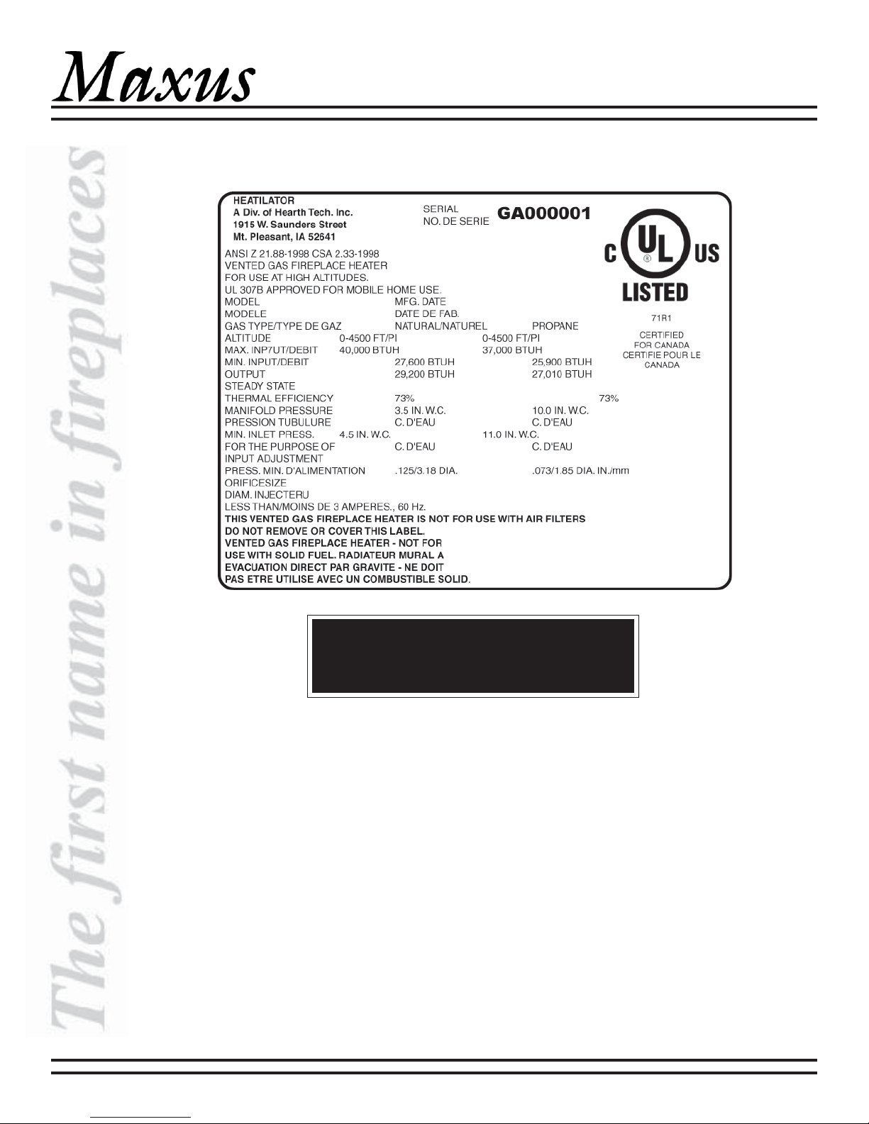
4. Efficiency
The efficiency rating of the appliance is a product
thermal efficiency rating determined under continuous
operating conditions and was determined
independently of any installed system.
If any assistance is required during installation please
contact your local dealer or contact the Heatilator
Technical Services Department, Hearth & Home
Technologies Inc., 1915 W. Saunders St., Mt. Pleasant,
IA 52641, 1-800-927-6841.
This appliance is approved for installation in
bedrooms and manufactured housing (mobile
homes) in the United States and Canada.
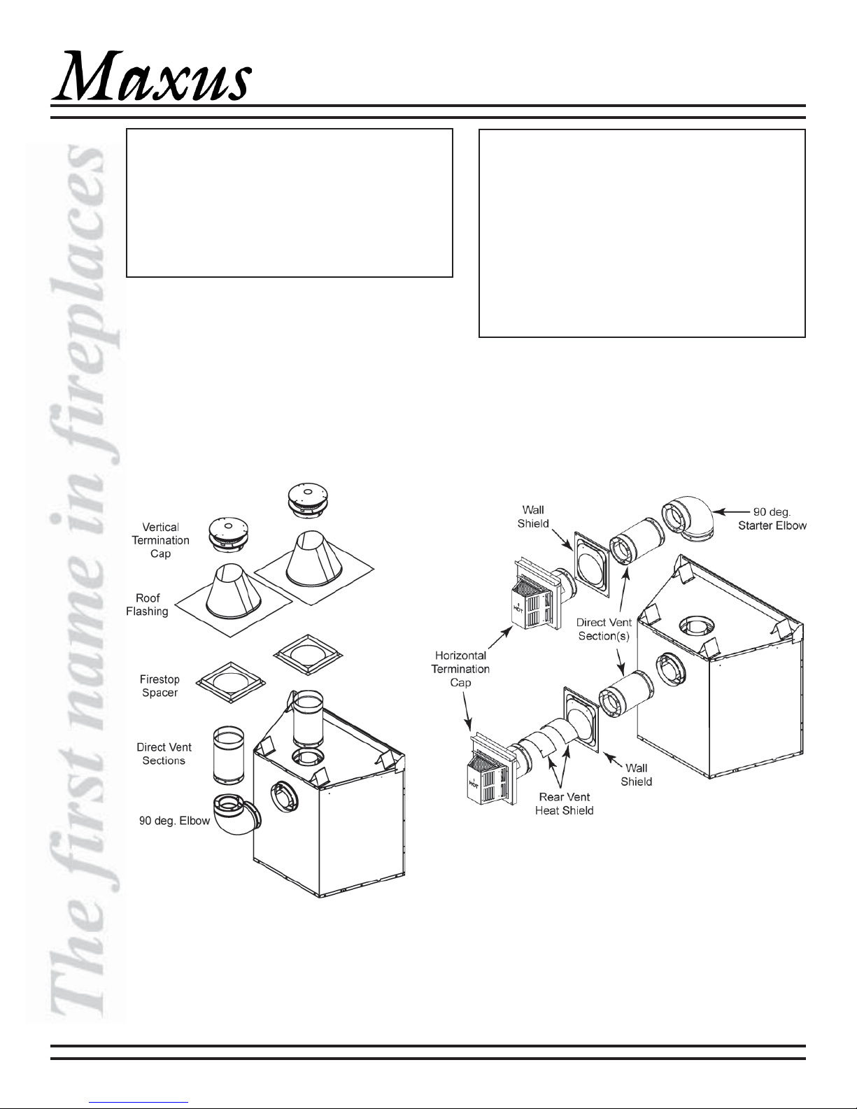
Note: Illustrations throughout these instructions reflect typical installations and are for design purposes only. Actual
installations may vary slightly due to individual design preferences. However, minimum and maximum clearances
must be maintained at all times.
The illustrations and diagrams used throughout these instructions are not drawn to scale.
WARNING!
This appliance is tested and listed for use only with the optional accessories listed in
these instructions. Use of optional accessories not specifically tested for this appliance
could void the warranty and/or result in a safety hazard.