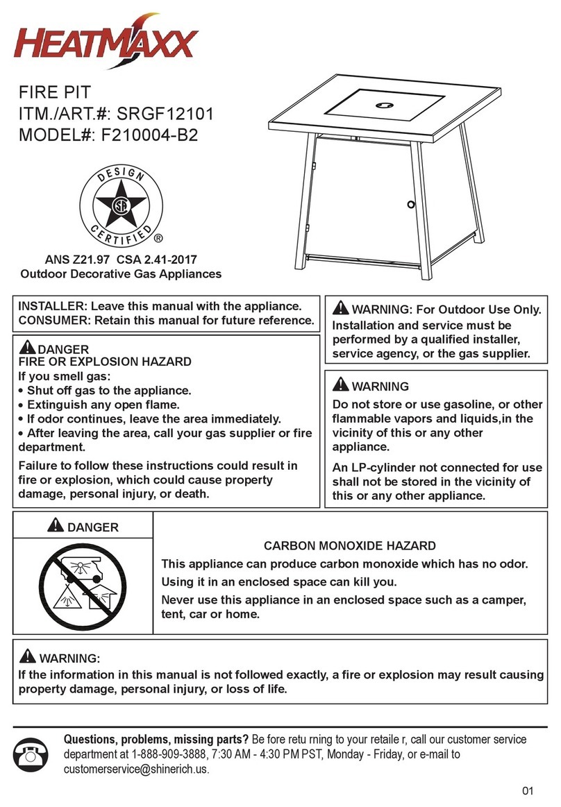
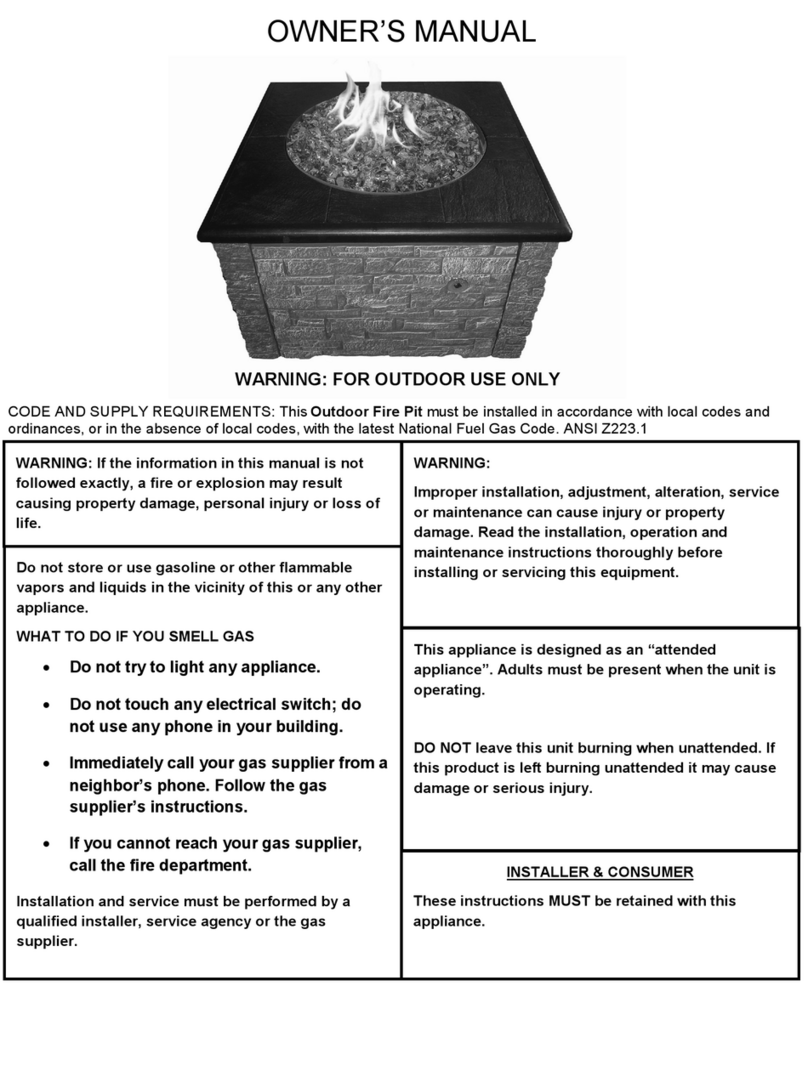
Heatmaxx SRGF11626 User manual

30" Gas Fire Pit
Questions, problems, missing parts? Be fore retu rning to your retaile r, call our
customer service department at 1-888-909-3888, 7
:00 AM 4:00 PM PST, Monday -
Friday, or e-mail to [email protected].
Model #: SRGF11626

2
WARNINGS AND CAUTIONS
Read the instructions before use. This appliance must be installed in accordance with such
regulations as are enforced.
sDo not try to light the appliance.
sDo not touch any electrical switch; do not use any phone in the vicinity of this product.
sImmediately call your gas supplier from a neighbor’s phone. Follow the gas supplier’s
instructions.
sIf you cannot reach your gas supplier, call the fire department.
WHAT TO DO IF YOU SMELL GAS?
Installation and service must be performed by a qualified installer, service agency or gas
supplier.
CARBON MONOXIDE HAZARD
This appliance can produce carbon monoxide which has
no odor.
Using it in an enclosed space can kill you.
Never use this appliance in an enclosed space such
as a camper, tent, car or home.
INSTALLER: Leave this manual with
the appliance.
CONSUMER: Retain this manual for
future reference.
FIRE OR EXPLOSION HAZARD
If you smell gas:
Shut off gas to the appliance.
Extinguish any open flame.
If odor continues, leave the area
immediately.
After leaving the area, call your gas
supplier or fire department.
Failure to follow these instructions
could result in fire or explosion,
which could cause property damage,
personal injury, or death.
DANGER
●
●
●
●
WARNING:For Outdoor Use Only.
Installation and service must be
performed by a qualified installer,
service agency, or the gas supplier.
Do not store or use gasoline or
other flammable vapors and liquids
in the vicinity of this or any other
appliance.
WARNING
An LP-cylinder not connected for use
shall not be stored in the vicinity of
this or any other appliance.
WARNING: If the information in this manual is not followed exactly, a fire or
explosion may result causing property damage, personal injury, or loss of life.

TABLE OF CONTENTS
Warnings and Cautions...................................................................2, 4-5
Table of Contents...................................................................................3
Tools and Parts...................................................................................6-7
Assembly Instructions.......................................................................8-15
Installation Instructions ........................................................................16
Operation.........................................................................................17-19
Locating Fire Pit For Use......................................................................20
Maintenance and Storage...............................................................21-22
Trouble Shooting..................................................................................23
Warranty Information............................................................................24
REMINDER
BEFORE ASSEMBLY
Verify that all parts are included with your gas fire pit BEFORE you begin assembly by checking the Parts and
Hardware List. For your convenience, some parts may be pre-assembled or attached to fire pit components.
If all parts are not included, do not attempt to assemble fire pit. Call the toll free number on the cover
page for replacement parts.
Leave hardware installed HALF-TIGHTENED on the gas fire pit during assembly until unit is completely
assembled, then finish tightening all hardware installed.
YOUR OWNER’S MANUAL
Keep and store this Owner’s Manual for future reference – it contains important instructions and
procedures for safety and maintenance.
3

4
IMPORTANT SAFETY INFORMATION
sThe installation must conform with local codes or, in the absence of local codes, with either the
Natural Gas and Propane Installation Code, CSA B149.1, or the Propane Storage and Handling
Code, CSA B 149.2.
sAlways place the appliance on a firm and level surface.
sDo not burn solid fuels in this gas appliance.
sUse the appliance outdoors in a well-ventilated space only, not in a building, garage, or any other
enclosed area.
sWhen using the appliance, keep the appliance area clear and at least 50 inches from combustible
materials, gasoline and other flammable liquid and vapors. Certain items or materials, when stored
under the appliance or nearby, will be subjected to radiant heat and could be seriously damaged.
s
Inspect the gas connections of appliance prior to each use. Do not operate the unit if there is gas leak.
s
Inspect the hose before each use of the appliance. The hose assembly must be replaced prior to the
appliance being put into operation if there is evidence of excessive abrasion or wear or if the hose is
damaged. The replacement hose assembly shall be that specified by the manufacturer.
A qualified service person should inspect the appliance annually.
sAlert children and adults to the hazards of high surface temperatures and keep them away
to avoid burns or clothing ignition.
sCarefully supervise children and pets when they are near the appliance.
sAny guard, barrier, or other protective device removed for servicing the appliance shall be
replaced prior to operating the appliance.
sDo not hang clothing or other flammable materials on or near the appliance.
sDo not use the appliance if any part has been under water. Immediately call a qualified service
technician to inspect the appliance and to replace any part of the control system and any gas
control which has been under water.
s
s
Use only a cylinder supply system arranged for vapor withdrawal, and the cylinder must include a
sThe LP-gas supply cylinder to be used must be: Constructed and marked in accordance with the
Specifications for LP-gas cylinders of the U.S. Department of Transportation (DOT); or the Standard
for Cylinders, Spheres and Tubes for Transportation of Dangerous Goods and Commission,
CAN/CSA-B339, as applicable;
The LP-gas supply cylinder to be used must be provided with a listed overfilling prevention device;
and provided with a cylinder connection device compatible with the connection for the appliance.
collar to protect the cylinder valve.
sThis appliance requires 20 lb (9 kg) LP gas supply cylinder.
sThe burner must be replaced prior to the appliance being put into operation if it is evident that the
burner is damaged. The replacement burner shall be that specified by the manufacturer.
sInstallation and repair should be done by a qualified service person. The appliance should
be inspected before use and at least annually by a qualified service person. More frequent
cleaning may be required as necessary. It is imperative that control compartment, burners,
and circulating air passageways of the appliance be kept clean.
WARNINGS AND CAUTIONS
5
This appliance is designed to operate with a standard 20 Ib propane cylinder with Approved
Cylinder Connection.
NOTE: PLEASE READ THE FOLLOWING SAFETY RULES:
Before beginning assembly of product, make sure all parts are present. If any part is missing or
damaged, do not attempt to assemble the product. Contact customer service for replacement parts.
Perform a leak test with a soapy solution:
1. To check gas connections.
2. After connecting a new cylinder.
3. Upon re-assembly after disassembly.
WARNINGS AND CAUTIONS
WARNING:
This product can expose you to chemicals including lead, which is known to the State of
California to cause cancer, and carbon monoxide, which is known to the State of California to
cause birth defects or other reproductive harm. For more information, go to:
www.P65Warnings.ca.gov.
!
SPECIFICATION
Certification CSA
Rated Heat Input 50, 000 Btu/h (14.65kW)
Fuel Propane
Gas Supply 20-lb. LP - gas cylinder
Manifold Pressure 11 in wc (2.74kPa).
Injector Size(diameter) 2.22mm
Min. gas supply for input adj. 25PSI (175kPa)
Max. gas supply 250PSI (1750kPa)

TOOLS NEEDED: (NOT INCLUDED)
Philips screwdriver
Estimated time for assembly: 30-45 minutes.
PACKAGE CONTENTS
6

Cylinder Locking Bolt
Cylinder Holder
Door Handle
Cylinder Holder Pole
Side Panel
PART DESCRIPTION QUANTITY PART DESCRIPTION QUANTITY
1A
3B
1C
3D
E
F
L
J
1
2
1
1
1
1
Cover Lid
Glass Chips
M
N
K
1
1
PACKAGE CONTENTS
Control Panel Assembly
Leg
Table Top Frame
HARDWARE CONTENTS (shown actual size)
M5 x 12 Bolt Assembly M5 x 12 Bolt M5 x 20 Bolt M6 x 12 Bolt ST4.2 x 9.5 Bolt
Qty. 4 Qty. 18 Qty. 4 Qty. 16 Qty. 4
AA CC DD EE
BB
7
Door
P
Q
Ceramic Tile
1
4
I
16
Leg With Door Magnet
Cushion Pad

Assembly Instructions
Choose a good, cleared assembly area and get a friend to help you put your gas fire pit together.
Lay cardboard down to protect gas fire pit finish and assembly area.
Step 1 Fig. 1
Hardware Used
AA M5 x 12 Bolt Assembly x 4
8
Position A
Position B
Position C
Thermocouple Position C
Thermocouple
Ground Wire
Position D
Ground Wire
Position D
Blade
Connector
Blade Connector Insulated Terminal
Insulated
Terminal
Then connect the electrode as position B,
B.1
B.2
B.3
connect the valve by
then
forcefully
to the
inserting the electrode
terminal into
comfirm therubbersleeve is placed on the
electrode wire wire
Then install the thermocouple as position C,
and install the ground wire as position D.
Place the table top frame (A) upside down
to the soft, level surface. Insert valve into
the injection pipe of burner as position A.
Attach control panel assembly (C) to the
table top frame (A) with (4) M5 x 12 bolt
assemblies (AA) as illustrated.
the valve terminal connector
B.2, finally,
connect the rubber
the valve as position B.3.
BladeConnector
Insulated
Terminal
Insulated
Blade Connector
Electrode Wire
Terminal
Electrode Wire
Rubber Sleeve
Rubber Sleeve
AA
electrode wire first as position B.1,
as position
sleeve to

Assembly Instructions
Step 2
Step 3
Fig. 2
Fig. 3
Attach side panel 1 (B) to two legs (D)
with (6) M5x12 bolts
Hardware Used
BB M5 x 12 Bolt x 6
Hardware Used
DD M6 x 12 Bolt x 12
9
(BB) as illustrated.
Attach a leg with door magnet (E) and
three legs (D) to the table top frame (A)
with (12) M6x12 bolts (DD) as illustrated.

Assembly Instructions
Step 5
Fig. 4
Fig. 5
Step 4
Attach cylinder holder pole (F) to two
legs (D) with (2) M5x20 bolts (CC) as
illustrated.
Hardware Used
CC M5 x 20 Bolt x 2
Attach side panel 2 (B) to two legs (D)
with (6) M5x12 bolts
Hardware Used
BB M5 x 12 Bolt x 6
10
(BB) as illutrated.
Note: The side with arrow sticker assemble
to the leg at front side.

Assembly Instructions
Step 6
Step 7
Fig.6
Attach side panel 3 (B) to a leg (D) and
leg with door magnet (E) with (6) M5x12
Hardware Used
BB M5 x 12 Bolt x 6
Attach another cylinder holder pole (F)
to a leg (D) and leg with door magnet (E)
with (2) M5x20 bolts (CC) as illustrated.
Hardware Used
CC M5 x 20 Bolt x 2
11
bolts (BB) as illustrated.
Fig.7
Note: The side with arrow sticker assemble
to the leg with door magnet (E).

AssembO\Instructions
Step 8
Step 9
Fig. 8
Fig.9
Screw cylinder locking bolt (L) to cylinder
holder (K) as illustrated.
12
Attach cylinder holder (K) to cylinder hold
poles (F) with (4) M6x12 bolts (DD) as
illustrated.
Hardware Used
DD M6 x 12 Bolt x 4
DD
DD

Assembly Instructions
Step 10 Fig.10
13
Screw door handle (J) to door (I)
as illustrated.
Fig.11
Step 11
Note: With the help of a friend, turn the
gas fire pit into upright position after this
step finished.
Hardware Used
EE ST4.2 x 9.5 Bolt x 4
Attach door (I) to the leg (D) with (4)
ST4.2x9.5 bolts (EE) as illustrated.

Assembly Instructions
Step 12 Fig.12
14
Fig.13
Peel and stick the cushion pads (P) on
the table top frame (A) as illustrated, total
16 cushion pads.
Note: Before applying the adhesive
cushion pads, be sure to wipe down the
metal surface and make sure it is free of
any dust or debris.
Step 13
Put (4)elbatno)Q(selitcimarec
top frame (A) as illustrated.

Assembly Instructions
Step 14 Fig.14
Put the glass chips (N) into the .potelbatfoelddim,aeragninrub
Place the cover lid (M) onto the tabletop
when the gas fire pit not use.
Note: To avoid ignition failure, do not
cover the shield with glass chips.
15
WARNING: Failure to position the parts in
accordance with these diagrams or failure to
use only parts specifically approved with this
appliance may result in property damage or
personal injury.
shield

glass chips (max15.43 lb)
Open the door (I)
Attach regulator to clylinder and turn clockwise by hand.
5. Turn the cylinder locking bolt clockwise to secure the gas
cylinder. (Fig.17)
INSTALLATION INSTRUCTIONS
16
is facing
(Fig.15)
Fig.18
6. Hang up the regulator as Fig.18 when the gas
cylinder takes out.
Fig.16
4. Make leakage solution by mixing 1 part liquid dish soap and 3 parts
water. Please do the Leak Test with leakage solution before use.
(Fig. 16)
Fig.17
Make sure the valve outlet of cylinder
assembly.
outward.
Your gas fire pit has been checked at all connections at the factory
for leakage.
In transportation and handling some connections may have loosened.
Follow these steps to check the hose/regulator/cylinder connections:
1)Make leakage solution by mixing 1part liquid dish soap and 3parts
water.
2)Spoon or brush several drops (or use squirt bottle) of thesolution
onto hose/regulator/cylinder connection.
3)Turn on gas cylinder. Inspect the connections and look forbubbles.
4)If no bubbles appear, the connection is safe.
5)If bubbles appear, there is leakage. Loosen and re-tighten this
connection. If there is still a leak, please please call our customer
service department at 1-888-909-3888 or e-mail to
Note:
1)The cylinder supply system must be arranged for vapor withdrawal.
2)The cylinder used must include a collar to protect the cylinder valve.
The hose assembly must be replaced prior to the appliance being put
into operation if there is evidence of excessive abrasion or wear, or if
the hose is damaged.
At least once a year, a complete inspection of the entire gas path
components should be performed.
If there is need to replace parts, proceed to leak test after reassembly
(These procedures should be performed by a profes-sional technician).
Check for the leaks
Check for
the leaks
II
Fig. 15

WARNING: DO NOT ATTEMPT TO OPERATE THE APPLIANCE UNTIL YOU HAVE READ AND
UNDERSTAND ALL PRECAUTIONS. FAILURE TO DO SO CAN RESULT IN PROPERTY
DAMAGE, SERIOUS INJURY, OR DEATH.
WARNING
WARNING
WARNING
FOR YOUR SAFETY:
DO NOT touch or move gas appliance
for at least 45 minutes after use.
Lighting operations should comply
with Lighting Instruction section.
Improper lighting operations will
cause serious injury and explosion.
Before turning gas supply ON
Your
fire pit was designed and approved for OUTDOOR
USE ONLY. DO NOT use it inside a building or any other
enclosed area.
Make sure surrounding areas are free of combustible
materials, gasoline, and other flammable vapors or liquids.
Ensure that there is no obstruction to air ventilation.
Be sure all gas connections are tight and there are no leaks.
Be sure the access panel is clear of debris.
Be sure any component removed during assembly or
servicing is replaced and fastened prior to starting.
FOR YOUR SAFETY:
WARNING!!!
Do not use an open flame to check for leakage.
Do not smoke during testing.
Do not test indoors.
A leak check must be performed whenever the gas
cylinder is replaced.
NOTE:
U
se only the pressure regulator supplied with this fire pit.
Replace them with those specified by the manufacturer
only.
OPERATION
If at any time you are unable to
light burner and smell gas, wait 5
minutes to allow gas to dissipate
before attempting to light gas
appliance. If after 1 minute, you
are unable to light burner, wait 5
minutes and allow flammable
vapors to dissipate before
attempting to light gas appliance.
17

ATION
Before Lighting
The gas fire pit should be thoroughly inspected before each
use, and by a qualified service person at least annually.
If relighting a hot gas fire pit, always wait at least 5 minutes.
Lighting Instructions
1. Make sure control knob is in the “OFF” position.
2. Turn LP cylinder gas valve to fully open position.
3. Press down control knob and turn it counter clockwise
to "LOW" position, this will light the burner. (You will hear 1
clicking noise.)
4. If the burner is not lit immediately (within 5 seconds), press
down the control knob and turn clockwise to "OFF" position,
repeat from step 3 after 5 minutes.
5. When burner is lit, turn the control knob to desired heat output position between "LOW"
and "HIGH".
Flame Characteristic
Normally the burner flame is yellow.
If the burner flame is blue and very small, please check the
gas cylinder, as it may be low gas pressure or empty. If there
is enough gas in the cylinder, please contact customer service
to change the burner of the gas fire pit.
If flames lift away from burner or backfire happens, or produce
thick black smoke, the fire pit should be turned off immediately.
The fire pit should not be operated again until the unit is serviced
and/or repaired by a qualified service technician.
WARNING: DO NOT ATTEMPT TO OPERATE THE APPLIANCE UNTIL YOU HAVE READ AND
UNDERSTAND ALL PRECAUTIONS. FAILURE TO DO SO CAN RESULT IN PROPERTY
DAMAGE, SERIOUS INJURY, OR DEATH.
OPERATION
18
P
u
s
h
t
o
t
u
r
n
OFF
HIGH
LOW

CAUTION: AVOID INHALING FUMES EMITTED FROM THE GAS APPLIANCE'S FIRST USE.
SMOKE AND ODOR FROM THE BURNING OF OILS USED IN MANUFACTURING WILL
APPEAR. BOTH SMOKE AND ODOR WILL DISSIPATE AFTER APPROXIMATELY 30
MINUTES. THE GAS APPLIANCE SHOULD NOT PRODUCE THICK BLACK SMOKE.
NOTE:
The burner may be noisy when initially turned on. To eliminate
excessive noise from the burner, turn the control knob to the
“LOW” position. Then, turn the knob to the level of heat desired.
Operation pressure checked:
If the flame is very small, this is because the supply
pressure is not enough. Please refill gas cylinder.
Re-light:
.noitisop "FFO" ot bonk lortnoc eht nruT)1
2)
3) Repeat steps beginning with step 3 of the lighting
instruction.
Shut down instructions:
1) Push in and turn control knob clockwise to "OFF"
position.
2)
2) Turn LP cylinder valve to "OFF" position.
The Event of Gas Leakage:
1) Turn the control knob to "OFF" position.
3) Wait 5 minutes to allow gas to dissipate.
4) If odor continues, immediately call gas supplier.
WARNING : Gas appliance will be hot after use.
Handle with extreme care.
Wait five (5) minutes before attempting to relight appliance.
Turn LP cylinder gas valve clockwise to "OFF" position
when appliance is not in use.
OPERATION
19
P
u
s
h
t
o
t
u
r
n
OFF
HIGH
LOW
P
u
s
h
t
o
t
u
r
n
OFF
HIGH
LOW

CAUTION: WHEN CERTAIN MATERIALS OR ITEMS ARE LEFT ABOVE, BESIDE OR UNDER
THIS APPLICANCE WHILE IN USE, THEY WILL BE SUBJECT TO RADIANT HEAT AND
COULD BE SERIOUSLY DAMAGED.
This gas fire pit is primarily used for the heating
of outdoor patios, decks, spas, pools and open
working areas.
Always make sure that adequate fresh air
ventilation is provided. Follow the
spacing tolerances shown in Fig. 19 at all times.
This gas fire pit must be placed on level, firm
ground.
Fig. 19
Never operate in an explosive atmosphere.
Keep away from areas where gasoline or other
flammable liquids or vapors are stored or used.
LOCATING FIRE PIT FOR USE
20
Table of contents
Other Heatmaxx Outdoor Fireplace manuals
Popular Outdoor Fireplace manuals by other brands

MODENO
MODENO OFG 141 owner's manual

Heat-N-Glo
Heat-N-Glo DAKOTA Installation & operating instructions

Uniflame
Uniflame 009 04 0500 owner's manual

Crawford & Burke
Crawford & Burke 9565TFP owner's manual

HPC
HPC 24SS50HWI?TRGH Installation & operation instructions

tropitone
tropitone Fire Pit Riser Assembly instructions

dellonda
dellonda DG190 manual

Sunnydaze Decor
Sunnydaze Decor WAR-962 owner's manual

MODENO
MODENO OFG308LP owner's manual

Blumfeldt
Blumfeldt Augustus manual

Endless Summer
Endless Summer GAD15021M owner's manual

Regency Fireplace Products
Regency Fireplace Products Plateau PTO50 Owners & installation manual