Heatmister DT-ETS WiFi User manual

1Model: DT-ETS WiFi
Model: DT-ETS WiFi

Model: DT-ETS WiFi
2Model: DT-ETS WiFi
WiFi Series Model: DT-ETS WiFi
Table Of Contents
2
1
1
2
3-4
5-6
7-8
9-11
11-12
13
13
14
15
Product Image
Table of Contents
What is a Room Thermostat?
Installation Procedure
LCD Display
WiFi Setup
Security Types and Compatibility
Remote Access Via App
Remote Access Via Web Browser
Temperature Display
Clean Screen
15
16
17
18
19-20
21
22
23
24
25-26
Locking the Keypad
Temperature Control
Frost Protection
Heating ON/OFF
Optional Features Explained
Adjusting the Optional Settings
Optional Settings - Features Table
Re-calibrating the Thermostat
Factory Reset
Wiring Diagrams

43 WiFi Series Model: DT-ETS WiFi
What is a Room Thermostat?
A room thermostat simply switches the heating system on and o as necessary.
It works by sensing the air temperature, switching on the heating when the air
temperature falls below the thermostat setting, and switching it o once this set
temperature has been reached.
Setting a room thermostat to a higher temperature will not make the room heat up
any faster. How quickly the room heats up, depends on the design & size of the heating
system.
Similarly reducing the temperature setting does not aect how quickly the room cools
down. Setting a room thermostat to a lower temperature will result in the room being
controlled at a lower temperature, and saves energy.
The way to set and use your room thermostat is to nd the lowest temperature settings
that you are comfortable with, and then leave it alone to do its job.
The best way to do this is to set the room thermostat to a low temperature – say 18°C ,
and then turn it up by 1°C each day until you are comfortable with the temperature. You
won’t have to adjust the thermostat further.
Any adjustment above this setting will waste energy and cost you more money.
Room thermostats need a free ow of air to sense the temperature, so they must not
be covered by curtains or blocked by furniture. Nearby electric res, televisions, wall or
table lamps may also prevent the thermostat from working properly.
This model DT-ETS thermostat has been specically designed to operate with electric
underoor heating systems.
Model DT-ETS is also equipped with dierent temperature sensor options to control
the electric underoor heating system. The thermostat’s built in sensor measures the
air temperature at the thermostat position within the room and uses measured values
to control the electric underoor heating system. Alternatively, optional remote air and
oor sensors can be connected with DT-ETS and remote temperature measurements
can be used instead to control the electric underoor heating system. The thermostat
enables easy switching between sensor modes providing a remote air sensor is
connected.
Please read the instructions fully to understand all of the features of this DT-ETS
thermostat.
65 WiFi Series Model: DT-ETS WiFi
1 2
3 4
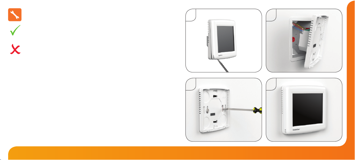
Installation Procedure
This WiFi Series thermostat is designed to be ush mounted and requires a back
box of 35mm (minimum depth) to be sunk into the wall prior to installation.
Step 1
Carefully separate the front half of the thermostat from the back plate by placing a
small at head terminal driver into the slots on the bottom face of the thermostat.
Step 2
Place the thermostat front somewhere safe.
Terminate the thermostat as shown in the diagrams on pages 25-26 of this booklet.
Step 3
Screw the thermostat back plate securely into the back box.
Step 4
Clip the front of the thermostat back onto the thermostat back plate.
Do
Mount the thermostat at eye level.
Read the instructions fully so you get the best from our product.
Don’t
Do not install near to a direct heat source as this will aect functionality.
Do not push hard on the LCD screen as this may cause irreparable damage.

87 WiFi Series Model: DT-ETS WiFi
1 2 3
15
14
13
1. Floor Temp Achieved Icon - Displayed when the oor set point temperature is reached.
2. Frost Icon - Displayed when the thermostat is in frost protection mode.
3. OFF Key - Single press to enable/disable frost protection or press and hold to turn
o display.
4. Flame Icon - Displayed when the thermostat is calling for heat.
5. Keypad Lock Icon - Displayed when the keypad is locked.
6. WiFi Icon - Flashes when the thermostat communicates with the receiver.
7. Battery Icon - Indicates current battery charge level.
8. Room Temp - Indicates the current temperature sensor mode.
9. Set - Displayed when the target temperature is adjusted.
10. Clean Screen - Freezes screen temporarily to enable cleaning.
11. Cancel - Used to exit setup/program operations.
12. Setup/Programming Keys - Used to navigate setup options.
13. Up/Down Keys - Increase or decrease values shown on bottom digit group.
14. Current Temp - Indicates the current sensor temperature.
15. Units of Temperature - Degrees Celsius or Fahrenheit.
LCD Display
7
6
9
11
12
45
8
10

109 WiFi Series Model: DT-ETS WiFi
Setting Up Your WiFi Thermostat
Step 1:
Download and install the WiFi thermostat setup utility from our web site:
www.heatmiser.co.uk/wi
Step 2:
Connect the thermostat to your PC with the USB cable provided. This will power the
thermostat through the USB port and will allow you to test the WiFi connection.
Open the setup utility and press Read to view the current thermostat conguration.
Step 3:
Enter the SSID, Security Type and Security Code of your wireless network.
These settings can usually be found on the underside of your wireless router.
For more information please consult your router manual.
See page 11 for additional information on security types and compatibility.
Step 4:
Enter a xed IP address for your WiFi thermostat outside of the router DHCP range.
It is likely that your network will be congured to operate on a DHCP basis.
This means your router automatically issues an IP address to a device that
successfully connects to the network.
Your WiFi thermostat needs a xed IP address in order for local and remote access
to operate and you must set this up manually.
Log into your wireless router and navigate to the LAN settings page.
Find and select the DHCP setup details.
This should dene the IP range that can be assigned to devices connecting to
the network.
As an example, you may have an IP starting range 192.168.1.1 and ending
192.168.1.99. This means you can safely provide your WiFi thermostat the IP
address 192.168.1.100 as no other devices will be assigned this address by the
router.
If your DHCP range is from 192.168.1.1 to 192.168.1.253 you cannot use 254 or
above.
You need to change the DHCP range, taking care not to change any of the rst
3 numbers.
Tip! When setting up an IP address, the rst three sets of numbers must be the
same as the router IP address and the fourth set must not be used elsewhere on the
network.
Step 5:
Enter the Subnet mask for the network.
This information can usually be found on the underside of your wireless router.
Step 6:
Enter the IP address of your gateway and DNS. In most cases, this is the IP
address of your wireless router.
If you have a multi-zone system and are using the Multi-Link, the Gateway of
the thermostat will need to be congured as the IP address of the Multi-Link.

1211 WiFi Series Model: DT-ETS WiFi
Step 7:
Create a unique username and password that will be used to access your thermostat
from a web browser.
Default Username: admin Default Password: admin
Change these settings to your personal preference and record for future use.
A 4 digit access PIN is required to use the smartphone/tablet app and also helps to
secure your system.
Step 8:
When you have entered the details of your WiFi network press Apply and disconnect
the USB cable, (the thermostat LCD should go blank).
Reconnect the USB cable to the WiFi thermostat, when the thermostat has rebooted it
will attempt to connect to your network. This process takes approximately one minute
and is complete when the WiFi symbol is displayed on screen.
Security Types and Compatibility
The WiFi Thermostats operate on the 802.11b standard.
If your router is a G model, you must ensure it is setup to work in B&G mode.
You will not be able to connect to your thermostat without changing this setting on
G model routers.
There are currently 4 common methods of securing your wireless connection:
OPEN/DISABLED (not recommended)
W.E.P. (lowest security level)
Your choice of security settings in the thermostat must match the setting in your
router. Often you will nd WPA and WPA2 are a single option in the router.
This is perfectly normal as the router automatically selects the correct security level
and you can set the thermostat up using either one of these settings.
Passwords can be up to 63 characters in length including spaces _. / \ characters.
The W.E.P. option is not so simple. Some routers generate a hidden password from
a pass phrase whilst others require a 10 or 26 digit hex password and won’t accept
anything else. Your thermostat utility can deal with both options but the following
restrictions may apply:
A hex password can only be made up of the numbers 0 to 9 and the letters a to f
(lower case only).
Hex passwords can only be 10 characters or 26 characters in length.
If a passphrase is used it must be either 5 or 13 characters in length but can be any
letter or number.
Your thermostat will automatically calculate the same hidden password your router
creates from the same phrase.
These restrictions are common to most routers but you should refer to the router
manual for specic restrictions that apply to your model.
W.P.A. (medium security)
W.P.A.2. (highest security)

Room Temperature SET Temperature
Temperature Display
The temperature display information is driven by two dierent inputs; the sensor
measurement and the target temperature you have set.
This is the current room temperature. This is the temperature you are trying to
achieve in your home.
When the thermostat is in air and oor sensing mode, the thermostat will display a
FLOOR button. Pressing this allows you to view the current oor temperature.
Pressing FLOOR again will return the thermostat to the room temperature display.
1413 WiFi Series Model: DT-ETS WiFi
To remotely connect to your WiFi Thermostat you must forward a port within your
router to your WiFi Thermostat.
As all routers are setup dierently, you should consult your user manual or the
manufacturer’s website for more information.
Generally you should create a new service within your router. Within this service
you must open TCP port 8068.
Use the port forwarding function to forward the new service to the IP address of
your WiFi thermostat.
Remote Access via App
To remotely access your WiFi Thermostat via a web browser you must rst open
port 80 and forward this to the IP address of your WiFi Thermostat.
Remote Access via Web Browser
To connect to your thermostat, open your preferred browser and enter the IP
address that you gave the thermostat during setup and press enter.
You will be asked to enter a password and username.
These are both set to“admin” as default.
We recommend you change these settings to ensure the security of your system.
For further information, click the help link within the browser.

1615 WiFi Series Model: DT-ETS WiFi
Locking the Keypad
The thermostat has a keypad lock facility.
• To activate the lock press the bottom right corner of the display and hold for 10s.
• When activated, you will see the Keypad Lock symbol.
• To cancel, press the bottom right corner of the display again for 10 secs.
Clean Screen
Pressing will disable all keys, providing you 15 seconds to wipe the screen
clean before the keys are re-activated.
Keypad Lock Indicator
The keys under the temperature display allow you to adjust the
set temperature.
When you press either of these keys, you will see the temperature and
the word SET appear on screen.
Select the desired temperature and press to conrm and exit.
Temperature Control
Set Temperature
Set Icon
1817 WiFi Series Model: DT-ETS WiFi
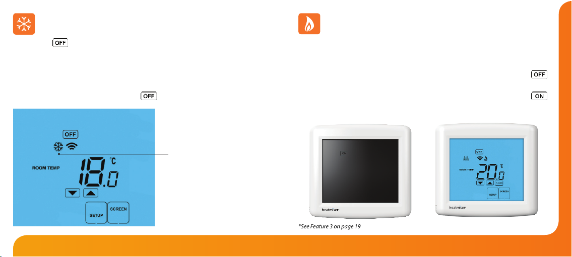
Heating On/O
Thermostat completely OFF Thermostat powered ON
*See Feature 3 on page 19
Pressing the key once will place the thermostat in frost protect mode.
In this mode, the thermostat will display the frost icon and will only turn the heating on
should the room temperature drop below the set frost temperature (see page 19).
Should the heating be turned on whilst in frost mode, the ame symbol will be
displayed.
To cancel the frost protect mode, press the key once.
Frost Mode
Frost Protection Mode Enabled
The heating is indicated ON when the ame icon is displayed.
When the ame icon is absent, there is no requirement for heating to achieve the set
temperature but the thermostat remains active.
To turn the thermostat OFF completely, press and hold the OFF key .......................
The display and heating output will be turned o completely.*
To turn the thermostat back ON, press the ON key once ...............................................

2019 WiFi Series Model: DT-ETS WiFi
THE FOLLOWING SETTINGS ARE OPTIONAL AND IN MOST CASES
NEED NOT BE ADJUSTED
Feature 01 – Temperature Format: This function allows you to select between °C or °F.
Feature 02 - Switching Dierential: This function allows you to increase the switching
dierential of the thermostat. The default is 1°C which means the thermostat will
switch the heating on 1°C below the set temperature and will turn it o when the set
temperature is achieved. With a 2°C dierential, the heating will switch on 2°C below the
set temperature and will switch o when the set temperature is achieved.
Feature 03 - Frost Protect: You can set whether the thermostat will maintain the frost
temperature when the thermostat display is turned o. As a default, this is enabled.
Feature 04 – Frost Protect Temperature: This is the temperature maintained when the
thermostat is in frost mode. The range is 07-17°C. The default is 12°C and is suitable for
most applications.
Feature 05 – Output Delay: To prevent rapid switching, an output delay can be entered.
This can be set from 00 - 15 minutes. The default is 00 which means there is no delay.
Optional Features Explained Feature 06 – Not used on this model.
Feature 07 – Temperature Up/Down Limit: This function allows you to limit the use
of the up and down keys. This limit is also applicable when the thermostat is locked
and so allows you to give others limited control over the heating system.
Feature 08 – Sensor Selection: This thermostat oers 5 sensor modes.
00 = Built in air sensor. In this mode, the thermostat will maintain the set
temperature by monitoring the built in air sensor.
Note: Built in air sensor only MUST NOT be used to control electric under-oor heating.
Floor sensor only or built in air & oor sensor together must be used.
01 = Remote air sensor. In this mode, the thermostat will maintain the set
temperature by monitoring the remote air sensor.
02 = Floor sensor. In this mode, the thermostat will maintain the set temperature by
monitoring the remote oor temperature.
03 = Floor sensor and built in air sensor. In this mode, the thermostat will maintain
the set temperature by monitoring the built in air sensor and will also ensure the
oor surface doesn’t overheat by monitoring the remote oor sensor.
04 = Floor sensor and remote air sensor. In this mode, the thermostat will maintain
the set temperature by monitoring the remote air sensor and will also ensure the
oor surface doesn’t overheat by monitoring the remote oor sensor.
Feature 09 – Floor Limit Temperature: This function allows you to set a maximum
oor temperature in order to protect the oor surface from overheating. This
function works for Sensor Modes 03 & 04 (see above) The default setting is 28°C.

2221 WiFi Series Model: DT-ETS WiFi
To adjust the optional settings, follow these steps.
• Press SETUP ..................................................................................................................
• Use the Up/Down keys at the top of the screen to select the feature
number (shown on page 22) and then use the Up/Down keys in the
center to adjust the setting ....................................................................................
• Press DONE to conrm settings and exit ...........................................................
Adjusting the Optional Settings
Feature Number
Setting Value
01
02
03
04
05
06
07
08
09
FEATURE
Temperature Format
Switching Dierential
Frost Protect
Frost Protection Temperature
Output Delay
Not used on this model
Up/Down Temperature Limit
Sensor Selection
Floor Temperature Limit
DESCRIPTION
00 = oC
01 = oF
(°C = Default)
0.5o- 3.0oC (1.0oC = Default)
00 = Disabled
01 = Enabled
(01 = Default)
07o- 17oC (12oC = Default)
Enter Value: 00 - 15 Minutes (00 = Default)
00o- 10oC (00oC = Default)
00 = Built in Air Sensor
01 = Remote Air Sensor
02 = Floor Sensor
03 = Floor Sensor and Built in Air Sensor
04 = Floor Sensor and Remote Air Sensor
20-45oC (28oC = Default)
SETTING
Optional Settings - Feature Table

2423 WiFi Series Model: DT-ETS WiFi
Calibration Temperature Setting
Set Icon
If you need to re-calibrate the thermostat, follow these steps.
• Press and hold the OFF key to turn the thermostat o .................................................
• Press and hold the ON key until the temperature appears on the screen .............
• Use the Up/Down keys to congure the new temperature ...............................
• Press DONE to conrm the new temperature ..................................................................
• Press the ON key once to turn the thermostat back on ................................................
Re-calibrating the Thermostat
All icons displayed simultaneously. Factory reset is complete.
The thermostat has a reset function to restore all settings to their factory defaults.
To perform a factory reset, follow these steps.
• Turn the thermostat OFF by pressing and holding the Power key.
Press and hold the bottom left corner of the LCD for 10 seconds .........................
• All of the screen icons will appear for 2 seconds and then disappear.
• Press the ON key once to turn the thermostat back on ............................................
Factory Reset
2625 WiFi Series Model: DT-ETS WiFi
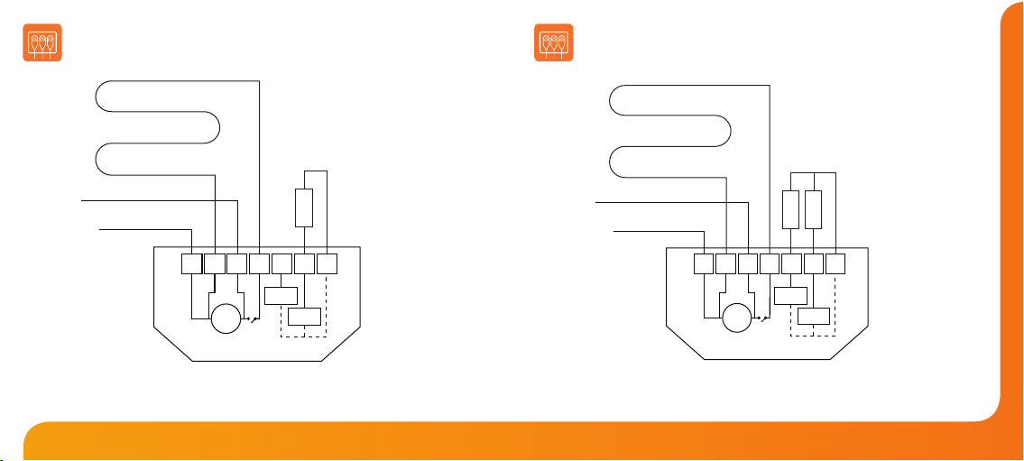
Wiring Diagram - DT-ETS WiFi
Wired with Remote Floor Probe
N.B. The mains supply must be properly protected and fused.
DT-ETS WiFi with remote oor and air probes for use in wet areas.
Remote
Probes
MATTING OR WIRE
Neutral
Live
Supply in
85V - 230V AC
Maximum load
16A AC resistive
DT-ETS WiFi
N N LOAD
LRT2 RT1 -
230VAC
Room
Sensor
Floor
Sensor
Floor
Air
MATTING OR WIRE
DT-ETS WiFi wired with remote oor probe used for normal
‘dry’ zones or where direct control of the oor is needed.
Neutral
Live
Supply in
85V - 230V AC
Maximum load
16A AC resistive
DT-ETS WiFi
N N LOAD
LRT2 RT1 -
230VAC
Room
Sensor
Floor
Sensor
Floor
Remote
Probe
Wiring Diagram - DT-ETS WiFi
Wired with Remote Floor and Air Probes

27 WiFi Series
Twitter: heatmiseruk
Facebook: facebook.com/thermostats
Want More Information?
Call our support team on: +44 (0)1254 669090
Or view technical specications directly on our website:
www.heatmiser.com
PDF FAQ
Heating Professionals:
Request a copy of our product
installation guide containing
detailed technical specications
for our complete product range:
www.heatmiser.com/guide
Table of contents
Other Heatmister Thermostat manuals


