CLIMASET Prossimo Series User manual
INSTRUCTION MANUAL
®
CLIMASET
Prossimo™ Series

Interactive controllers
®
CLIMASET
®
Climaset is under continuous development. Both the described products and document contents
may be changed or withdrawn without any previous notice. The scope of the warranty and
® ®
responsibility of Climaset applies to the device only. Under no circumstances shall Climaset be
responsible for any special, incidental, consequential, or indirect damages, howsoever caused.

Contents
®
Enjoying your Climaset safely ................................................................. 4
®
Introducing your Climaset ...................................................................... 6
Indicators on the screen and adjustments.................................................. 6
Smartikeys™: adjusting all settings with a single touch ............................ 10
Summary of steps to adjust your thermostat ............................................. 11
Installing the device easily ...................................................................... 13
Appendix A. Miniature circuit breaker (MCB) selection guide ....................... 16
Appendix B. Thermostat selection guide and wiring diagrams ............ 17
Appendix C. Extra settings ....................................................................... 43
Appendix D. Troubleshooting .................................................................... 46
Appendix E. Technical specifications ......................................................... 48

4
Enjoying your Climaset safely
®
®
The instructions below have been prepared to help you enjoy using your Climaset
safely for many years. Please read it thoroughly before starting to use the device.
Ÿ Each air conditioning device should be protected by its own miniature circuit
breaker (MCB).
Ÿ Each thermostat is intended to control a single air conditioning unit. We do not
recommend control of multiple units with a single thermostat.
Ÿ If you ever encounter device malfunction, switch the respective MCB off and
contact customer service.
Ÿ Should you notice that your air conditioner is not protected by an MCB, ask your
electrician to add one for you. You may find proper recommended MCB specifications
in Appendix A.
Ÿ The MCB rating should be selected according to the required current for the normal
operation of your air conditioner. Using higher ratings, protection is not assured.
®
Ÿ Your Climaset also protects itself as well as your air conditioner with a fuse. In case
of a burnt fuse, please check for malfunction of your air conditioner and thermostat,
incorrect wiring, or short circuit. It may also indicate that the thermostat cannot
supply the necessary current for the air conditioner. You may need to add a relay
®
Enjoying your Climaset safely

5
between the thermostat and the air conditioner. Refer to Appendix B.
Ÿ Always replace the fuse with one of the same type. Fuses have several
specifications other than their current rating. Check Appendix E for the proper type of
fuse. Contact your local customer service if an extra fuse is necessary.
Ÿ Never bridge the fuse with a wire or replace it with one of a higher rating.
Ÿ Before screwing the wires to the device terminals, use the wire ferrules supplied
with the device. This will avoid the possibility of a short circuit. We recommend using
AWG 16 (1.5 mm) cables.
Ÿ Never use detergent to clean the thermostat surface. It may leave undesirable
marks on the surface of the thermostat, especially on the screen. Always use a soft,
moist tissue to clean the device.
Ÿ Should liquid crystal leak from the screen, avoid all contact with the eyes, mouth,
and skin.
Ÿ The device is not designed to work in places with condensing humidity.
Ÿ Strong electromagnetic fields, such as powerful radio transmissions, can distort the
screen content or cause device malfunction.
Ÿ Never try to fix the device yourself. Replacement of the parts may affect the safe
®
usage of the device. Always contact your local Climaset service center for repair.
®
Enjoying your Climaset safely

6
®
Introducing your Climaset
® TM
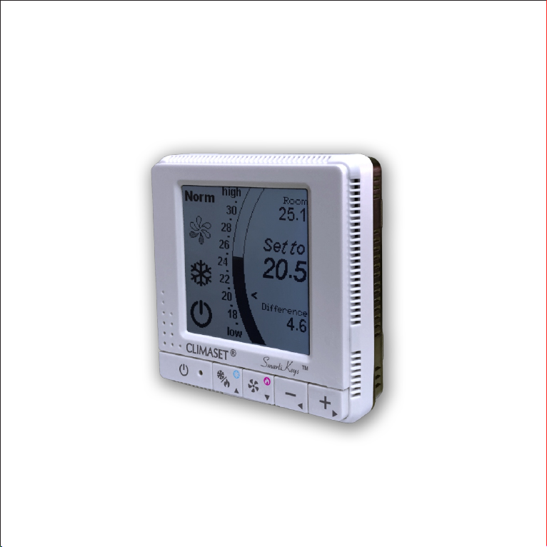
The Climaset Prossimo series is the most compact, ultra-slim wall-mount
thermostat ever designed. With its large screen and multi-function keys, it is a new
frontier in functionality standards in the thermostat industry.
TM
The Smartykeys one-touch automatic adjustment is easy to operate even for those
who find it difficult to work with digital thermostats. Now, there is a single assigned
key for the frequently used adjustments, such as fan speed, desired temperature,
and heat/cool selection. Even advanced adjustments in the “Extra settings” screen
tm
are easy in the Prossimo series because of the existing navigation-based system of
the keys.
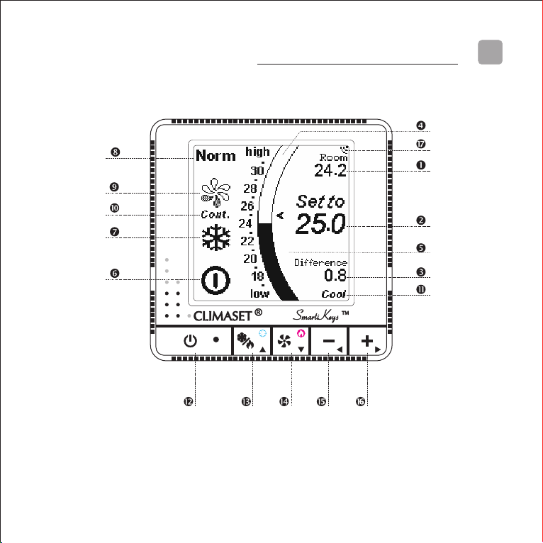
Indicators on the screen and adjustments
The figure on the next page shows the display indicators and adjustments. The
following section describes in detail the role of each indicator on the screen and how
to manually adjust them.
ΠRoom temperature: Indicates the existing room temperature.
Set to: Your desired room temperature. Use the “+” key to increase or the“-” key to
decrease the set temperature.
?The adjustment steps for setting the temperature have been reduced to 0.5°C in
this new model to satisfy the most discriminating demands.
? Pressing the “+” or “-” key for a while speeds up the increase or decrease of the set
temperature.
®
Introducing your Climaset
7
Ž Difference reading: Room temperature variation from the desired temperature,
set in .
Temperature bar graph: The room temperature is shown graphically by the curved
bar graph. It is updated every few seconds and remains unchanged until the next
reading.
Indicators on the screen and adjustments

8
Graphical temperature setting indicator: An arrow on the right side of the
temperature bar graph shows the desired room temperature graphically, set in .
‘ Power status: This shows the power status of the device. It may display one of the
following indicators:
The device is in standby mode. In this mode, the thermostat displays your setting
along with the room temperature, but the air conditioner is not turned on until you
switch back to the operational mode. This mode is useful if you do not use your air
conditioner for a long period, such as in the spring or autumn, when you are on a trip,
or in rooms that are used rarely.
The device is in operational mode. The air conditioner will be switched on or off
automatically according to your settings.
Use the power key ( ) to switch between operational and standby mode.
’ Heating/cooling operation mode: This indicator specifies whether the device is
operating in heating, cooling, or, if the device supports it, automatic heat/cool
changeover or fan-only mode. Use the heat/cool changeover key ( ) to switch
between these modes.
? “Automatic heat/cool changeover mode” means the device may automatically
change between heating or cooling based on the setting and the room temperature.
This mode may not be supported by all air conditioners and accordingly may not be
available in all thermostat models.
? The fan-only mode is useful if you need the air conditioner to just blow air without
heating or cooling. In this mode, the thermostat does not switch the air conditioner
off unless the power off key is pressed. This mode is not supported by all air
conditioners and thermostat models and should be enabled in “Extra Settings” as
described in Appendix C.
?Not adjusting this setting correctly will cause the malfunction of your air conditioner.
Indicators on the screen and adjustments

9
Indicators on the screen and adjustments
Choose fo r cooling, for heating, or, if your device supports it, for automatic
heat/cool or for fan-only mode.
“ Fan operation modes: The following fan operation modes are available:
ŸNormal fan operation mode: The air conditioner runs with the adjusted fan speed
whenever the thermostat restarts the air conditioner.
Ÿ Automatic fan speed changeover mode: The fan speed is proportional to the
temperature difference between the room and the set point. As the room
temperature approaches to the set point, the fan speed drops. You will benefit from
the maximum capability of your air conditioner whenever it is required, in the hottest
hours of the day, and you will enjoy quiet fan operation whenever possible
throughout the rest of the day, and you will save a considerable amount of energy.
” Fan speed: This displays the adjusted fan speed. The number of blades is
proportional to the determined fan speed.
? The icon displays the determined fan speed. The device may be on or off because
of the difference between the room and the desired temperatures or the power
status setting. In such a case, the fan speed icon is shaded gray to indicate that the
air conditioner apparatus is actually off.
Use the fan speed key ( ) to change the fan speed. If the fan speed is high and you
press the fan speed key again, the automatic fan speed changeover mode will be
selected and the thermostat determines the fan speed based on the difference as
indicated in section Ž of the screen. A greater difference results in a higher fan
speed, reducing the time needed to reach to the desired set point. Pressing the fan
speed key ( ) again exits the automatic fan speed changeover mode and returns to
the normal mode. The minimum fan speed will be selected again accordingly.
Continuous fan operation: If your air conditioner is capable of performing in
continuous fan operation mode and your thermostat model supports this option, you

10 Smartikeys™: adjusting all settings with a single touch
may enable the continuous fan operation mode as described in Appendix C. In this
mode, the fan never switches off, but the thermostat controls the room temperature
by switching on or off components other than the fan, such as a compressor, an
electric valve, etc. If this mode is selected, a “Cont.” sign appears as shown in the
figure.
Heat/cool activation indicator: If the thermostat controls components other than
the fan, it indicates their status. “Heat” or “Cool” means that the thermostat
commands heating or cooling. If two stages of heating and cooling are available for
your air conditioner and thermostat, they may be displayed as “Cool1” or “Heat1” for
the first stage and “Cool2” or “Heat2” for the second stage. Also, if the thermostat
directly controls a compressor for heating as a heat pump or cooling, a 3-minute
restart delay is necessary to equalize the pressure on the compressor to prevent
overload on its electro motor during startup. During these 3 minutes, a recycle delay
warning is indicated on the screen.
Beep sound indicator: This indicates whether the key press beep is enabled or not.
Press for 5 seconds to turn it on or off. and hold the power key ( )
? This has no effect on the confirmation beep sound for remote controller
commands.
Smartikeys™: adjusting all settings with a single touch
Determine whether you need to adjust the thermostat for cooling or heating. To
adjust the device for cooling, just press the key with the blue snowflake sign ( ) for 5
seconds; to adjust it for heating, press the key with the red flame sign ( )for 5
seconds. The device will respond with a long beep. This means all the necessary
11
settings have been made. You do not need to press any more keys. These default
settings have been optimized for most people and most environments.
? If the difference indicated on the display (Ž) is below 1°C, the device may not turn
on immediately. This means that the current room condition is at a comfortable level.
The device will switch on as the temperature difference increases.
Summary of steps to adjust your thermostat
If you are not going to use the air conditioner for a while, switch the thermostat to
standby mode. The display should indicate standby ( ) (‘). If it is not, just press the
power key ( ). The standby icon will appear. Otherwise, if you are going to use your
air conditioner, the operational mode indicator ( ) should appear on the display. If it
does not, just press the power key ( ). The operational mode indicator will show up
there.
‚ Use the heat/cool operation mode key to select heating or cooling. A flame
indicator on the screen (’) indicates that the device has been adjusted for heating,
while a snowflake represents cooling. A combined heat/cool indicator, if available,
shows that the device may automatically change between heating and cooling based
on the set temperature and the room temperature. A blow sign indicates that the fan-
only mode has been selected, and the air conditioner will continue to blow without
heating or cooling the air. The last two modes may not be supported by all air
conditioner types and accordingly may not be available in all thermostat models.
ƒ Adjust your desired fan speed using the fan speed key ( ). If the highest fan speed
Summary of steps to adjust your thermostat

12
is selected and the fan speed key ( ) is pressed again, the device enters the
automatic fan speed changeover mode, which determines the most desirable fan
speed automatically. To select the fan speed manually again, press the fan speed key.
The device will exit this mode and the lowest fan speed will be selected.
„ Use the “+” ( ) Or “-” ( ) key to increase or decrease the set temperature. 25°C is
normally suitable for most people and environments.
®
Enjoy using your Climaset .
Summary of steps to adjust your thermostat
13
Installing the device easily
The instructions below have been prepared to assist you in the installation of the
device. Please read the instructions throughly and carefully before installing the
device. Following all the steps as described guarantees your safety and the
functionality and endurance of the thermostat and air conditioner.
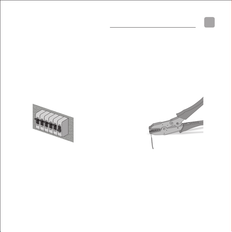
Installing the device easily
Turn off the respective circuit
breaker. Do not try to install the
device while the circuit breaker is on.
It may not only put your safety at risk
but also the sparks produced while
securing the wires may shorten the
life of some components within the
device.
‚ Use a crimping tool to secure the
wire ferrules supplied with the device
on the wires to prepare them to be
screwed into the terminals. The best
wire size is AWG16 (1.5 mm
diameter), but wires up to AWG12
(2.5 mm diameter) can also be used
in the thermostat terminals.

14
latches
latches
3 to 5 mm tip
Installing the device easily
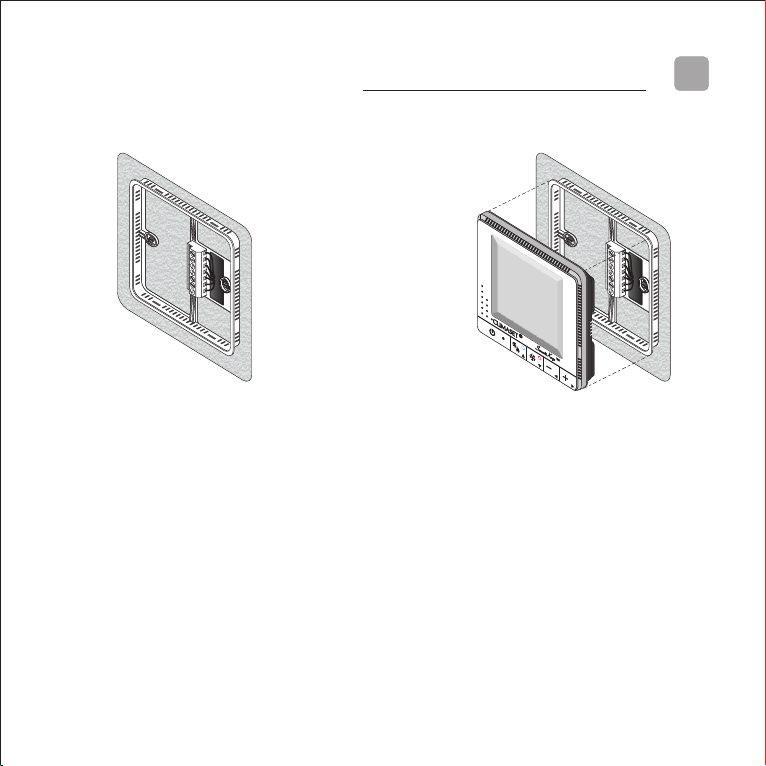
ƒ Release the back wall mounting
plate. There are four latches, as
illustrated in the figure, two at the top
and two at the bottom of the
thermostat. Use a screwdriver with a
tip between 3 and 5 mm to gently
release them. After releasing each of
the latches, pull the respective device
corner a little to keep the latch from
snapping in again. Pull the device
straight out from the back mounting
plate after releasing all four latches.
„ Position the mounting plate on the
wall. Use a pencil to mark the
mounting holes. Remove the plate
from the wall and drill 3/16” holes in
the wall. Tap anchors into the drilled
holes. Reposition the plate and
loosely insert two mounting screws in
the holes. Level the plate for
appearance. Tighten the mounting
screws.
? You may also use it over a standard
60x60x40 mm conduit box. The screw
holes match the holes of the conduit box
and cover the box completely.
15
… Wiring techniques: The function of
the wires and their respective
positions in the thermostat terminals
vary based on type of air conditioner
and thermostat. The proper wiring of
the device is es sentia l in its
functionality. You may find proper
wiring techniques for several types of
air conditioners and thermostats in
Appendix B. Please match the
thermostat carefully with your air
conditioner and follow the wiring
instructions as illustrated.
† Mounting the unit: Hold the
thermostat face parallel to the wall
surface. Do not incline the thermostat
face. Match the needles on the back
of the thermostat with the holes on
the terminals of the mounting plate.
push the thermostat gently over the
needles until the latches snap closed.
‡ Turn on the circuit breaker. The
device will be operational.
Installing the device easily
16
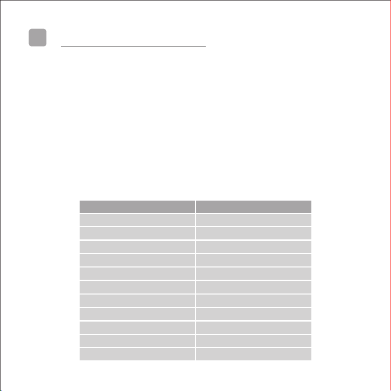
Appendix A. Miniature circuit breaker (MCB) selection guide
The following table provides a guideline to select the proper type of miniature circuit
breaker to protect your air conditioner and therefore your thermostat. The nominal
rating of the proper circuit breaker has been estimated based on the air handling
capacity of the air conditioner. If the specified type of circuit breaker in the air
conditioner catalogue differs from what is specified here, it overrules the following
table. The specified type of circuit breaker proposed by the air conditioner
manufacturer should be used.
? Always use Type C miniature circuit breakers. Type C has been assigned for
inductive loads, such as the load of an electro motor.
Air handling capacity (CFM)
Nominal rating (A)
200
1
300
1
400
1
600
1
800
2
1000
2
1200
3
1400
3
1600
4
1800
4
2000
4
Appendix A.
17
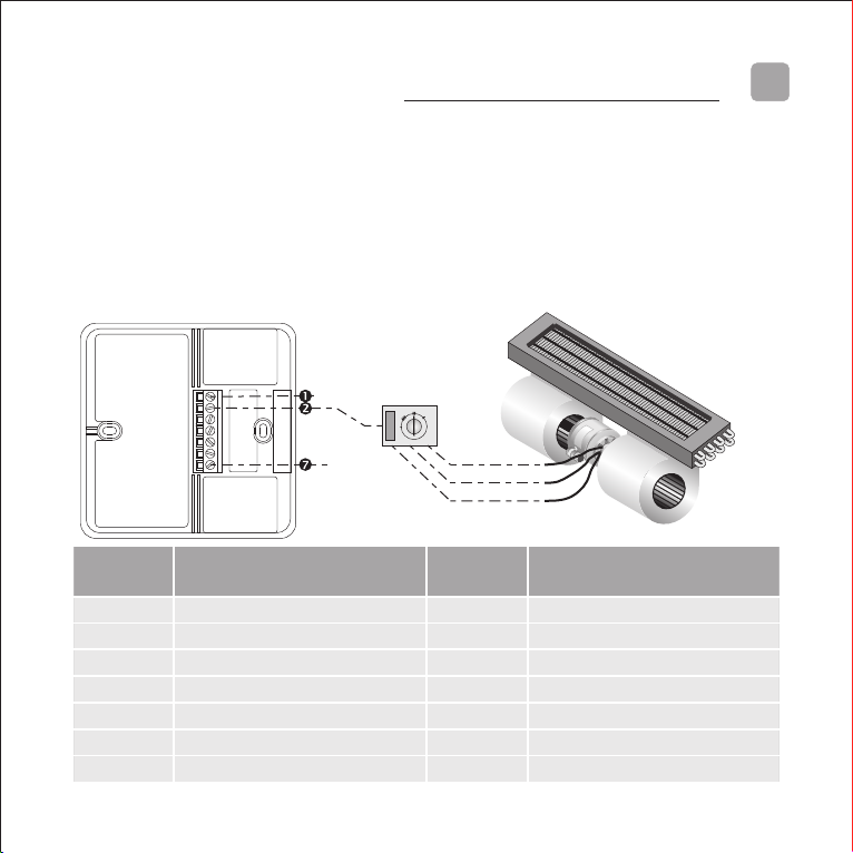
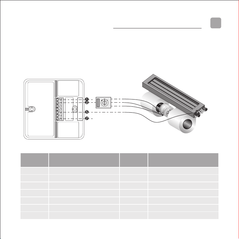
Appendix B. Thermostat selection guide and wiring diagrams
Air conditioner type: Vertical room fan coil
Appropriate thermostat: Prossimo 3100
OFF
Null
Fan
Line High
Medium
Low
Appendix B.
Terminal
number
Description
Input/
Output
Electrical characteristics
1
Null
Input
AC 220V / 24V 50Hz
2
To fan speed selector
Output
AC 220V / 24V 50Hz
3
Do not connect
-
-
4
Do not connect
-
-
5
Do not connect
-
-
6
Do not connect
-
-
7
Line
Input
AC 220V / 24V 50Hz
18
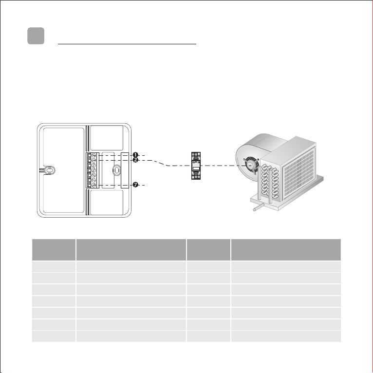
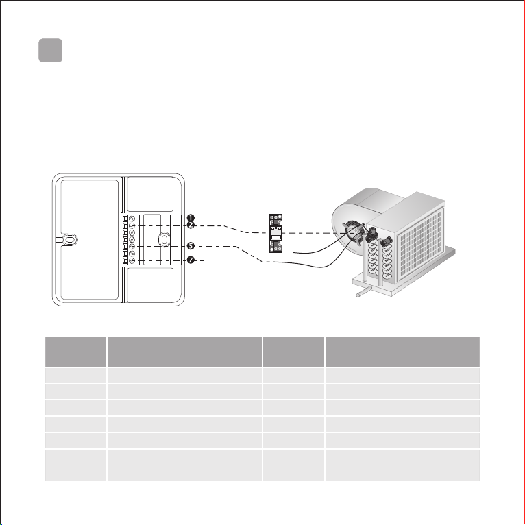
Air conditioner type: Single-speed ducted fan coil
Appropriate thermostat: Prossimo 3100
Relay
Null
Fan
Line
Appendix B.
Terminal
number
Description
Input/
Output
Electrical characteristics
1
Null
Input
AC 220V / 24V 50Hz
2
To fan speed selector
Output
AC 220V / 24V 50Hz
3
Do not connect
-
-
4
Do not connect
-
-
5
Do not connect
-
-
6
Do not connect
-
-
7
Line
Input
AC 220V / 24V 50Hz
19
Air conditioner type: Two-pipe vertical room fan coil with on/off normally closed
valve
Appropriate thermostat: Prossimo 3110A
Terminal
number
Description
Input/
Output
Electrical characteristics
1
Null
Input
AC 220V / 24V 50Hz
2
To fan speed selector
Output
AC 220V / 24V 50Hz
3
Do not connect
-
-
4
Do not connect
-
-
5
To normally closed valve
Output
AC 220V / 24V 50Hz
6
Do not connect
-
-
7
Line
Input
AC 220V / 24V 50Hz
OFF
High
Medium
Low
Null
Fan
NC Valve
Line
Appendix B.
20
Air conditioner type: Single-speed, two-pipe ducted fan coil with on/off normally
closed valve
Appropriate thermostat: Prossimo 3110A
Relay
Null
Null
Fan
Line
Terminal
number
Description
Input/
Output
Electrical characteristics
1
Null
Input
AC 220V / 24V 50Hz
2
To fan speed selector
Output
AC 220V / 24V 50Hz
3
Do not connect
-
-
4
Do not connect
-
-
5
To normally closed valve
Output
AC 220V / 24V 50Hz
6
Do not connect
-
-
7
Line
Input
AC 220V / 24V 50Hz
NC Valve
Appendix B.
Other manuals for Prossimo Series
1
This manual suits for next models
16
Table of contents
Other CLIMASET Thermostat manuals


