Heatrae Sadia Carousel Guide

1
ELECTRIC SHOWER
INSTALLATION and USER INSTRUCTIONS
ref. 3600 5640 issue 4
PLEASE READ AND UNDERSTAND THESE INSTRUCTIONS BEFORE
COMMENCING INSTALLATION
PLEASE LEAVE THESE INSTRUCTIONS WITH THE USER
CarouselCarousel
CarouselCarousel
Carousel
The quality name in water heating
HIGH
LOW
START
STOP
LOW FLOW

2
Figure 1 Internal components
Fixing Lugs
Thermal cutout
Pressure
Switches
Front cover
Heat
exchanger
Water control
valve
Outlet pipe
Pressure relief device
Removable
bottom
section
Inlet spigot
Fixing lug
Alignment
post
Drain slot
L & N
terminal
block
Earth
terminal
block
Back plate
Low flow neon
Power selector
switch
Solenoid
valve
Neon Board
CONTENTS
Internal components .......................... p2
Wiring diagrams ................................ p3
TECHNICAL SPECIFICATIONS ........ p4
IMPORTANT INFORMATION ............ p4
How an instant electric shower works p6
SITING AND PLUMBING .................. p6
Things you must do ........................... p6
Things you must not do ..................... p8
ELECTRICAL INSTALLATION........... p8
CONNECTING TO SERVICES ......... p9
Preparation ........................................ p9
Cable entry ...................................... p10
Pipe entry ........................................ p10
Plumbing ......................................... p10
Electrics ........................................... p11
Fitting the front cover ....................... p12
Commissioning ................................ p12
USER INFORMATION ..................... p12
Maintenance .................................... p13
Inspection ........................................ p14
FAULT FINDING ..................... p15 - p17
GUARANTEE & SERVICE POLICY p17
ENVIRONMENTAL INFORMATION p17
Approved Spares Stockists .............. p20
Address and phone numbers........... p20
CAROUSEL
Rating Label
Stop/Start
switch

3
Cut
Out
NL
Terminal
block
Solenoid
1
2
High
Low
Start
Stop
Low flow
red
red
red
blue
white
black
red
white
black
violet
green/yellow
MID
LH
black
brown
red
brown
red
blue
Power setting
switch
Pressure
switches
black
RH
3
red
red
Stop/Start switch
Heat
exchanger
Figure 2 Wiring diagram 7.2 & 8.5kW
Cut
Out
NL
Terminal
block
Solenoid
1
2
Heat
exchanger
High
Low
Start
Stop
Low flow
red
red
red
blue
white
black
red
white
black
violet
green/yellow
RH
LH
black
brown
red
brown
red
blue
Power setting
switch
Pressure
switches
black
Stop/Start switch
Figure 3 Wiring diagram 9.8 & 10.8kW

4
2 IMPORTANT INFORMATION
2.1 Your shower is designed and tested
to the very highest standards and complies
fully with all of the relevant national/
international standards for safety and
reliability. The shower is manufactured in
a BS EN ISO 9001:2000 -registered
factory - your assurance of a quality
product.
2.2 To ensure correct use and
maintenance of the shower, please read
and adhere to the following warnings and
guidelines.
FOR INSTALLERS
2.3 The Installation must comply with the
Building Regulations Part P and the Water
Regulations. Where there is a new
installation, or a replacement product is
not identical to the one being replaced, the
cable sizes, circuit protective devices,
bonding and other requirements of the
Building Regulations must be assessed
by a (registered) qualified and competent
electrician, who should carry out the
installation taking into account the site
conditions.
2.4 WARNING: THIS APPLIANCE
MUST BE EARTHED.
2.5 Before removing your shower heater
cover always ensure your shower heater
is isolated from the electrical mains.
2.6 This product is splash-proof and is
approved for use in shower cubicles and
over baths. However, do not install the
shower heater in a position where the
handset, in its normally-parked
position, will consistently direct the
spray over it.
2.7 To comply with the Water
Regulations a servicing valve must be
1 TECHNICAL SPECIFICATIONS
1.1 CONNECTIONS
Inlet connection -15mm ext. diameter
spigot for
compression fitting.
Water entry point - Top, bottom, rear and
right hand side.
Cable entry point - Top, bottom and rear.
1.2 ELECTRICAL
Nominal Power Rating
1.3 MATERIALS
Backplate, cover
and control knob - ABS
Elements - Copper sheathed rod
type
1.4 DIMENSIONS
Height - 262mm
Width - 185mm
Depth - 107mm
1.5 STANDARDS AND APPROVALS
Complies with the requirements of
EN 60335-2-35.
British Electrotechnical Approvals Board
(BEAB) approved.
Complies with European Community
Directives (CE).
edoC.dorP gnitarrewoP
V042@
gnitarrewoP
V032@
89512059)A03(Wk2.7)A92(Wk6.6
93612059)A53(Wk5.8)A43(Wk8.7
54512059)
A14(Wk8.9)A93(Wk0.9
64512059)A54(Wk8.01)A34(Wk9.9

5
fitted in the pipework to the shower, in an
accessible place. This will be of great
benefit if any maintenance work or
complete replacement of the shower is
required later on.
2.8 This shower is designed for domestic
use and is not vandal-resistant. If it is
installed in an institutional or commercial
situation, frequent inspection may be
necessary, and our guarantee may be
affected.
FOR USERS
2.9 If water emerges from anywhere
other than the spray head outlets, do not
use your shower, TURN OFF
ELECTRICITY and refer to the Fault
Finding section.
2.10 IT IS IMPORTANT TO CLEAN THE
SPRAY PLATE REGULARLY, particularly
in hard water areas, where this may be
necessary as often as once a week.
Failure to do so will affect the
performance of the shower and in
extreme cases may cause the pressure
relief device (PRD) to operate - see Fig.
1 and Fault Finding (p15-17).
Refer to the handset user instructions for
handset maintenance information.
2.11 The shower heater outlet, hose
and handset act as a vent. They must
not be blocked, obstructed, or have
connected to them any fitting not
approved by the manufacturers. The
use of unapproved accessories may
invalidate the guarantee and affect the
performance and safety of the unit.
2.12 WARNING! DO NOT USE the
shower if the HOSE IS DAMAGED in any
way; for instance if the outer covering has
parted to reveal the inner tube.
A damaged hose can suddenly restrict the
flow and result in extremely hot water
being emitted from the spray head.
A damaged hose could completely block
the outlet of the shower; the resulting
increase in pressure could burst a
weakened or damaged hose.
2.13 Do not install the shower in a situation
where the water in it could freeze. Any
damage caused by freezing will not be
covered by the guarantee.
WARNING. If you suspect your shower
is frozen, DO NOT SWITCH ON. If you
have switched on, SWITCH OFF
IMMEDIATELY. Refer to Fault Finding
(p15-17).
2.14 Do not leave the infirm, disabled
users, or young children unattended in the
shower.
2.15 Before stepping into the shower,
always test the temperature of the spray
with your hand.
2.16 Switch off at the isolating switch after
use. This is a safety procedure
recommended with ALL electrical
appliances.
2.17 As with all electrical appliances, it is
advisable to have your shower and
installation checked at least every two
years by a competent electrician, to
ensure that there is no deterioration due
to age and usage.
2.18 Shampoo and shower gel should be
stored using the gel hook and soap dish
(where provided) and must not be placed
on top of the shower unit.

6
3 SITING AND PLUMBING
3.1 Spend some time planning exactly
where to site the shower heater and riser
rail. Bear in mind the height of people who
will be using it.
THINGS YOU MUST DO
3.2 Check that the water pressure to
the shower is adequate. If in doubt,
consult a competent plumber.
Maximum and minimum pressures are:-
Maximum - 1 MPa
Minimum
- up to and including 9.5kW: 0.09 MPa
- over 9.5kW: 0.11 MPa
Running pressure with at least 5 l/min
flow rate
The use of other services connected to
the water pipe supplying the shower heater
may cause the water pressure to drop
below the minimum. Therefore this should
be taken into account.
The following conversions may be useful:
1 bar = 14.5 lbf/in²
= 33.3 ft head of water.
= 10m head of water
= 0.1 MPa
1 lbf/in² = 2.3 ft head.
3.3 Electric shower heaters are normally
plumbed into the mains water (except for
special low pressure versions). However,
the shower heater may be fed from a
storage tank as long as there is a sufficient
head of water.
3.4 Mount the shower heater on a flat
vertical wall with the outlet, to which the
hose is connected, pointing downwards,
using three suitable wall plugs and screws.
3.5 DO NOT place the shower heater
where it will be in the direct spray from a
normally-parked handset.
Heating
element
ON
Pressure switch
on/off
switch
Cold
water
inlet
Flow
control
lectrical
Terminals
Power selector switch
HOW AN INSTANT ELECTRIC
SHOWER WORKS
2.19 When the user starts the shower by
pressing the stop/start button, the flow
control lets in the water. If there is
sufficient water pressure, the pressure
switch will turn on the heating elements.
2.20 The element in the heat exchanger
will start to heat the water and this takes
typically 10-20 seconds.
2.21 By controlling the flow rate of water
over the heating elements, it will be
warmed up to the correct temperature.
Reducing the flow rate will increase the
water temperature and vice versa.
2.22 The shower has high and low settings
that give further control of temperature.
2.23 The temperature of the incoming
water varies, mains water can be as low
as 5°C in the winter and as high as 20°C
in the summer. This affects the output
temperature of the shower which is only
able to raise the temperature of the water
by a given amount, depending upon the
flow rate and power setting.
Figure 4 Schematic of typical electric shower

7
Figure 5 Siting of riser rail and heater
25mm minimum
Lowest possible
handset position
Bath/Shower Tray
610mm (24)
Highest Position
Riser rail
Hose-retaining ring
Lowest position
Shower
heater
305mm (12)
3.6 Allow room around the shower heater
for removal of the front cover.
3.7 Position the riser rail close to the
heater, not necessarily on the same wall
(but bear in mind paragraph 3.5) so that
in its highest parked position, the handset
is not more than 610mm (24”) above the
bottom of the heater, and in its lowest
position it is no lower than 305mm (12”)
below the heater - see Fig. 5.
3.8 If the handset can reach to within
25mm (1”) of the spillover level of the bath,
shower tray, wash basin, WC or bidet, then
to prevent the possibility of back-
siphonage of used water (Water
Regulations Guide G15.14/R15.14) you
must either:-
1. Fit a hose-restraining ring - see Fig. 5.
2. Fit a double-check valve in the
pipework to the shower.
3.9 Decide from which direction your inlet
pipe will enter the shower heater. There
is a choice of entry from top, bottom, right
hand side or rear - see Fig. 10.
3.10 Ensure there are no services such
as gas, water pipes, electrical or telephone
cables beneath the surface of the wall
before drilling.
3.11 The water connection to the shower
heater should be made using standard
15mm outside diameter copper pipe or a
stainless steel pipe. The ends of the pipe
should be cut square and be free from
internal and external burrs and deep
scratches.
3.12 Cut all necessary pipework to length
with a pipe cutter and not a hacksaw, to
minimise swarf - see Fig. 6.
Figure 6 Cutting pipes
Figure 7 Flushing the pipework

8
Figure 8 Schematic of typical electrical layout
Double pole isolating switch:
pull cord or wall mounted in accordance
with IEE regulations
Shower unit
(use rear entry when it is possible)
RCD (can be part of the
consumer unit)
Meter
80A or 100A main switch
Consumer unit
Meter ‘tails’
4 ELECTRICAL INSTALLATION
WARNING
4.1 This appliance must be earthed.
4.2 The installation must comply with the
Building Regulations Part P. Where there
is a new installation, or a replacement
product is not identical to the one being
replaced, the cable sizes, circuit protective
devices, bonding and other requirements
of the Building Regulations must be
assessed by a (registered) qualified and
competent electrician, who should carry
out the installation taking into account the
site conditions.
The following notes are for guidance only:
4.3 The shower heater must only be
connected to a 230/240V ac supply.
3.13 Before making the final water
connections to the shower heater, the
pipework MUST BE FLUSHED
THOROUGHLY to remove brick dust,
swarf etc. which could severely damage
the shower itself - see Fig. 7.
3.14 A Water Regulations Advisory
Service listed servicing valve should be
fitted in the water supply pipe to the
shower. This is to allow the shower heater
to be serviced without turning off the water
supply to other appliances.
THINGS YOU MUST NOT DO
3.15 DO NOT use plumber’s paste on any
joints as this may damage the shower.
3.16 DO NOT use a blow-torch or other
form of heat close to the shower heater
as this may damage the nonmetallic parts.
3.17 DO NOT use excessive force, but do
ensure adequate support, when making
connections.
4.4 Before making any electrical
connections within the installation,
make sure that no terminal is live. If in
doubt, SWITCH OFF the whole installation
at the consumer unit or switch fuse (where
fitted).
4.5 It is strongly recommended that a
30mA rcd is incorporated in the circuit,
even if it is not required to comply with BS
7671.
4.6 A double-pole isolating switch with a
contact separation of at least 3mm in each
pole, must be incorporated in the circuit.
This must have a mechanical indicator
showing when the switch is in the OFF
position. A neon lamp alone is not
sufficient.

9
5 CONNECTING TO SERVICES
PREPARATION
5.1 Remove the three fixing screws
which hold the front cover onto the
backplate. Note that the lower screw is
longer than the upper two.
5.2 Carefully remove the cover which
holds the control knob by pulling directly
away from the backplate.
Bottom
section
Figure 9 Removing cover
5.3 Carefully take out the removable
bottom section of the backplate by lifting
its sockets clear of the pegs on the
backplate. This allows greater access for
installing the cable and pipe. Keep it safe,
as it could easily be damaged.
5.4 Decide which entry points you will use
for cable and water pipe - see Fig. 9.
5.5 Decide where to mount the shower,
refer to Section Three for guidance.
Ensure that you leave enough room
around the shower for removal of the front
cover for inspection or servicing at a later
date.
5.6 It is best to mount the shower on top
of any tiling, so that it can be replaced
easily in the future without requiring
re-tiling. If you must tile around the
shower, DO NOT grout right up to the
shower backplate as this makes
subsequent removal difficult. Do not seal
the shower to the wall using bath sealant,
as the shower will not be harmed by water
dripping behind it.
5.7 When the cable and pipe entry points
have been decided, remove the relevant
areas of the backplate and/or removable
bottom section using a sharp knife and a
round file.
CAUTION. These are not knock-outs.
Figure 10 Backplate dimensions (mm)

10
there would not be enough room within
the pipe channel in the shower to
manoeuvre the elbow onto the spigot.
5.14 Side Entry. You must use a straight
connector with an overall length (including
nuts and olives) of less than 42mm.
PLUMBING
5.15 Decide where to connect to the water
mains for your feed to the shower. Ensure
that the pipe you have selected is not a
gas pipe (they can look similar) or a hot
water pipe or from a cold water storage
tank (unless you have sufficient head - see
3.2 & 3.3).
5.16 Cut the necessary pipework to
length, assemble and offer up to the
installation before making any soldered
joints. Ensure that the pipe is the correct
length, as shortening it can be difficult
once joints have been made.
CABLE ENTRY
5.8 Available entry points:- top, bottom
and rear (rear is generally the easiest).
Side entry is not possible. The thinned
areas in the backplate and bottom section
are suitable for a cable size up to 16mm².
5.9 For rear entry, cable must emerge
from the wall only in the areas specified in
Fig. 9. You will need at least 280mm of
cable to emerge from the wall to allow
connection to the terminal block.
PIPE ENTRY
5.10 Available entry points:- top, bottom,
rear and right hand side (bottom is
generally the easiest). The inlet spigot is
smooth, 15mm diameter and is designed
to accept a 15mm compression fitting.
This must be an elbow for top, bottom and
rear entry, and a straight connector for side
entry. You should use compression rings
(olives) made of copper rather than brass,
as copper will crush down better onto the
plastic spigot. Push-fit connectors cannot
be used.
5.11 Rear Entry. If the pipework is to
enter from the rear, you must cut away
the wall from around the pipe to allow room
for the nut on the compression elbow to
be recessed into the wall - see Fig. 11.
The pipework must be connected to the
elbow BEFORE the shower is fitted to the
wall; if you were to fix the pipe in place
first, you would not be able to get a
spanner onto the compression nut.
5.12 Depending on the type of
compression elbow used, you may need
to remove a small part of the bottom
section of the backplate in order for it to fit
over the elbow nut.
5.13 Top Entry. You must connect the
ELBOW to the INLET SPIGOT first; if you
were to connect the elbow to the pipe first,
Figure 12 Connecting pipe - bottom, top & RH
Bottom Top Right hand
Use compression fitting
Figure 11 Connecting pipe - rear entry

11
5.17 Carry out any cutting with pipe cutters
in preference to a hacksaw, to minimise
swarf. Use 15mm compression fittings,
preferably with copper compression rings
(olives), for the connection to the shower
heater.
5.18 Remember to incorporate a servicing
valve and, if required, a double-check
valve - see 3.8 & 3.14.
5.19 Locate your stop cock and turn off
the water supply. Check that the pipe
you intend tapping into no longer carries
water, by opening a tap that the pipe
supplies.
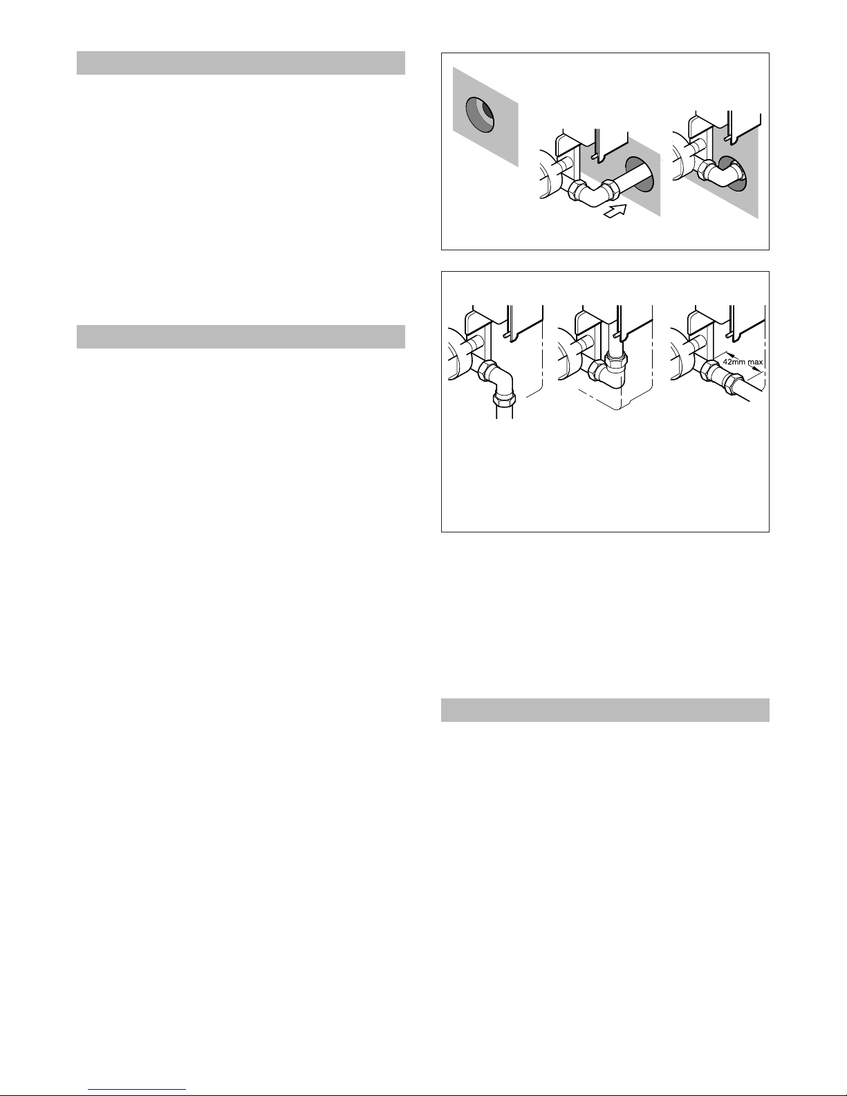
5.20 Make your connection to the pipe. If it
is on a low-lying loop there may be some
water left in the pipe, so be prepared for
some flow of water. Make all joints except
that to the shower heater before flushing.
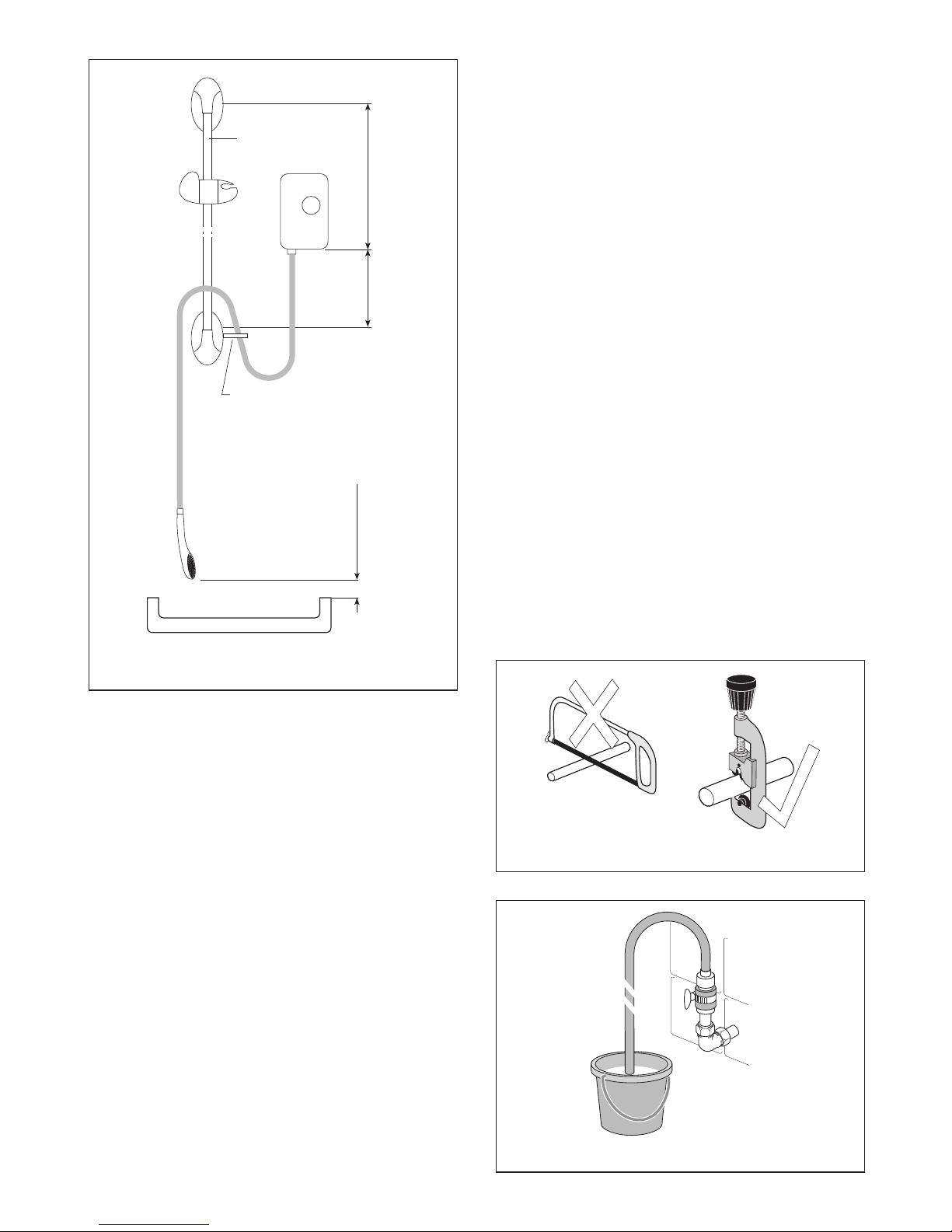
5.21 It is essential to flush the system
in order to clear debris, particles of
solder and swarf which could enter and
damage components within the
shower heater, prior to connecting to
the shower - see Fig. 7. It may be best
to take the shower off the wall to do this.
5.22 Turn the water off after flushing,
either at the stop cock or by using your
servicing valve.
5.23 Remount the shower firmly and make
the final water connection to it. Turn the
water on again.
5.24 No water will flow from the shower
outlet until the electrics are connected, as
the shower incorporates a solenoid valve.
5.25 Check for leaks in all pipework, and
rectify as necessary.
5.26 When the shower fitting is complete
the riser rail and accessories can be fitted,
please refer to separate instructions in
accessory box.
ELECTRICS
5.27 Design your system as outlined in
Section Three. Lay the cable in your
chosen route, ensuring that you have
ample length.
5.28 Leave the connection to the
consumer unit or switch-fuse until last.
5.29 Remember, when working on
electrical components, ensure they are
not live. If in any doubt, switch off at your
main switch at the fuse board or consumer
unit.
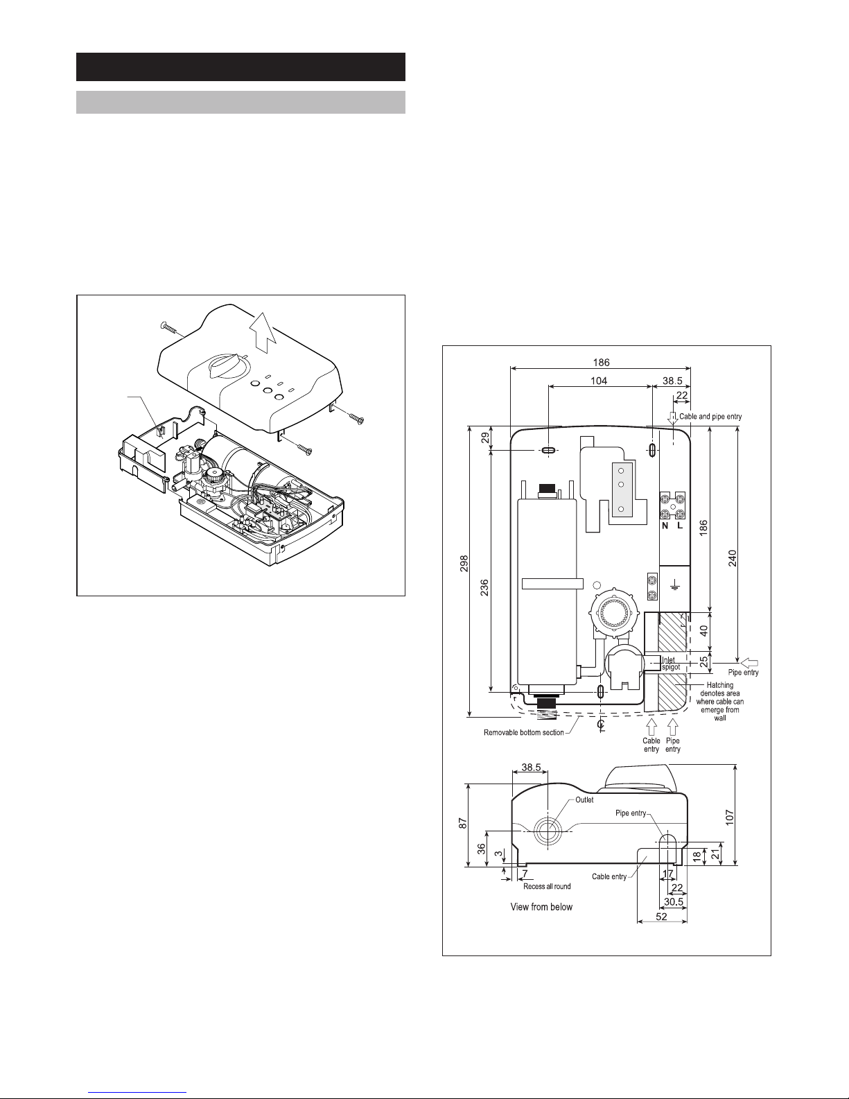
5.30 If you find it necessary to increase
access for fitting the cable, the shower can
be unplumbed at its inlet pipe and
temporarily removed from the wall.
5.31 Feed the cable through the opening
in the backplate below the terminal block.
5.32 Make sure that you route the cable
so that the bottom section of the backplate
will fit in place.
5.33 Ensure that all three screws hold the
shower backplate to the wall firmly.
5.34 Strip the outer insulation sheath back
as required.
5.35 Strip the insulation from the cores and
make connections to the LIVE (L) (brown
or red), NEUTRAL (N) (blue or black) and
EARTH terminal block. The earth wire
must be sleeved green/yellow. Make sure
that the cores of the cable lie tidily and do
not touch any metallic part of the shower.
They must not be under strain. There is no
cable clamp.
5.36 Ensure that the cable does not foul
the area above the bottom removable
section, where the knob gear will fit when
the front cover is fitted into place.

12
6 USER INFORMATION
6.1 To turn on and set temperature:
1. Turn the shower isolating switch to
ON.
2. Press the ‘Low’ button. (‘High’ may
be selected once flow and
temperature have been established.)
3. Turn the water control knob
anticlockwise. Water will flow from the
handset, power light will come ON.
4. Select either ‘High’ or ‘Low’ and adjust
the water control knob to achieve
preferred shower temperature.
WARMER
DECREASE FLOW:-
Turn water control knob clockwise
and/or select ‘High’ power setting.
COOLER
INCREASE FLOW:-
Turn water control knob anticlockwise
and/or select ‘Low’ power setting.
5. Make adjustments carefully. Give the
shower a few seconds after each
adjustment to stabilise, then check the
temperature by hand before stepping
into the shower.
5.37 Make sure that all the terminal block
screws are tightened very firmly. Replace
the bottom section of the backplate.
FITTING THE FRONT COVER
5.38 Turn the valve fully clockwise (open).
Turn the water control knob in the cover
so that the pointer is at the 7 o’clock
position.
5.39 Carefully fit the cover to the backplate,
ensuring that the lugs slide into their
sockets. You may have to adjust the water
control knob slightly to enable its gear to
mesh with that of the control valve.
NOTE: The alignment post on the
underside of the cover fits into the recess
in the centre of the valve gear to aid the
fitting of the cover.
5.40 Fit the cover fixing screws. The
longer one is for the lower fixing point. You
may have to push the front cover firmly
against the backplate seal, to enable the
screws to locate properly.
COMMISSIONING
Once the installation of the shower is
complete, the following tests should be
carried out to ensure the installation
instructions have been correctly adhered
to and the shower is functioning as it
should.
5.41 Secure the handset on the riser rail
where it can spray safely. Press ‘Low’
button.
5.42 Turn the water control knob fully
clockwise.
5.43 Turn the shower mains isolating
switch to ON. Turn on water isolating valve
(if applicable).
5.44 Press the ‘Start Stop’ button, the ‘Start
Stop’ and the ‘low flow’ lights should come on.
5:45 Slowly turn the water control knob
anticlockwise. There may be gurgling
noises as water fills the heat exchanger,
then water will start to flow from the
handset. Press the ‘High’ button.
5.46 Turn the water control knob further
anticlockwise until the ‘low flow’ light goes
out. The elements are now heating.
5.47 The temperature of the spray should
now increase.
5.48 Adjust the water control knob to give
the desired temperature.

13
6. The ‘LOW’ power setting uses less
power and can be used in the warmer
periods when incoming water
temperature is higher. They can also
be used to obtain a cooler spray
without adjusting the water control
knob.
7. If ‘low flow’ light comes on it indicates
the shower is not heating; turn the
water control valve anticlockwise.
A cold shower cannot be obtained.
6.2 To turn off the shower:
1. Press the Start Stop button.
2. Turn the shower isolating switch to
‘Off’.
6.3 Indicator Lights
1. ‘START STOP’
ON when shower is operating.
OFF before ‘Start Stop’ is pressed.
2. ‘LOW FLOW’
HIGH
LOW
START
STOP
LOW FLOW
Figure 13 External features of shower
High setting button & light
Water Control Knob
Low flow light
Low setting button & light
Start stop button & light
ON when the water control knob is turned
too far clockwise, the pressure switch
turns off the heating element. The shower
is not heating.
OFFwhen shower is heating. Normal
condition.
3. ‘HIGH’
ON when high setting is selected.
4. ‘LOW’
ON when low setting is selected.
Please note that this shower is
not
thermostatic, it will not keep spray
temperature constant whatever the
change in external influence.
MAINTENANCE
Cleaning the Handset
Also refer to instructions supplied with
handset.
6.4 To obtain the best performance from
your shower, the handset must be cleaned

14
regularly, maybe as often as once a week
in hard water areas.
6.5 This is because the fine outlet holes
can become blocked with scale and this
will affect the pattern of the spray and
cause the heater to perform poorly.
6.6 The easiest and most effective
method of cleaning your handset,
regardless of which type you have with
your shower, is to soak it in a proprietary
descalant. For best results the handset
should be left to soak overnight.
6.7 The handset with rubber spray outlets
can be cleaned by simply rubbing one’s
hand over them firmly to dislodge the
scale.
INSPECTION
6.8 We recommend that in the interests
of safety the shower and its electrical
installation is checked by a qualified
electrician at least every two years.

15
SYMPTOM
1. No flow or not
enough flow.
2. Flow adequate
but water too
cold.
POSSIBLE CAUSE
A. Electrical power to
shower heater off.
B. Water control knob is
turned fully clockwise.
C. Water turned off at
mains or servicing
valve.
D. SHOWER HEATER
SUSPECTED OF
BEING FROZEN.
E. There may be an
outlet blockage.
F. Cover/knob fitted
incorrectly, limiting
knob movement.
A. Shower heater is on
the ‘LOW’ power
setting.
REMEDY
A. Ensure that the electricity supply to the shower is
switched on, and ‘Start Stop’ light is lit.
B. Turn water control knob anticlockwise.
C. Ensure water is fully turned on at the mains and at
servicing valve in circuit.
D. If so, DO NOT USE.
1. Switch off immediately at isolating switch.
2. Turn water off at servicing valve (if fitted) or at stop cock.
3. Contact our Service Department.
E. Disconnect handset from hose and run the shower.
1. If water flows, then handset is blocked with scale or
debris. Remember that disturbances to plumbing
elsewhere in your house, or in the street, can dislodge
debris which can find its way to the shower. Clean the
handset and spray rings/plate thoroughly. See
Maintenance, Section 6.
2. If the water does not flow, remove hose from the
shower outlet.
2a If the water flows then the hose is blocked. This could
be due to damage, severe kinking or even an
obstruction. Replace with a new hose.
2b If the water does not flow, there is a blockage in the
plumbing to the shower, or the shower itself. Contact
our Service Department if the shower is considered to
be the problem.
F. Switch off at isolating switch. Remove front cover and
refit as in paragraph 5.38, taking care to position the
knob correctly.
A. Ensure that the shower is on ‘HIGH’ setting, where
applicable.
7 FAULT FINDING
In the unlikely event of a problem, consult the trouble shooting chart below.
For your particular symptom follow the suggested remedies in the order given. If you are
unable to remedy the problem, CONTACT YOUR INSTALLER IN THE FIRST INSTANCE.
Do not attempt any electrical or plumbing work unless you are competent to do so.

16
SYMPTOM
2. Flow adequate
but water too
cold
(continued)
3. Water too hot.
4. Water runs from
around hose.
Pressure relief
device (PRD)
has operated
due to excess
pressure build-
up.
5. Temperature
varies while
showering,
cycling hot/
cold.
POSSIBLE CAUSE
B. Water flow too high.
A. Water flow too low.
B. Sprayplate blocked
with scale and debris.
C. Water pressure too low.
D. Cover/knob fitted
incorrectly, limiting
knob movement.
A. Handset Blocked.
B. Hose damaged or
kinked.
A. Thermal cut-out is
operating, normally
making a ‘click’ as it
does so.
B. Input pressure is below
the minimum required
(see 3.2). Flow is
unstable.
REMEDY
B. Reduce the flow by turning the water control knob
clockwise slowly. NOTE: If the knob is turned too far
clockwise, the safety pressure switch inside the
shower will turn off the heating elements. This is
apparent when the indicator light on the shower goes
out and/or the ‘low flow’/’reduce temp’ light (where
applicable) comes on. If this happens, turn the knob
anticlockwise until the light(s) revert to their original
state.
A. Increase the flow by turning the water control knob
anticlockwise slowly.
B. Clean the handset sprayplate.
C. Switch to ‘low’ setting, if applicable.
D. Switch off at isolating switch. Remove front cover and
refit as in paragraph 5.38, taking care to position the
knob correctly.
Turn off isolating switch and servicing valve.
A. Clean out the sprayplate as in ‘Maintenance’ Section 6.
Call a service engineer to remove the front cover and
reset the PRD by removing the bent bracket, pushing
the black outlet boss back into the heat exchanger, and
refitting a new bracket.
If the fault occurs again without the hose being
damaged or the handset blocked, contact our Service
Department.
B. Replace kinked or damaged hose and reset as in ‘A’.
If the fault occurs again without the hose being
damaged or the handset blocked, contact our Service
Department.
A. Increase the flow by turning the water control knob
anticlockwise. Clean the handset and sprayplate.
B. Ensure that your stop cock and servicing valve are fully
open. If they are, ask your installer or the local water
company to check that the running pressure is above
the minimum required (see 3.2).

17
7 FAULT FINDING
continued
Where a fault cannot be corrected by
either yourself or your installer, contact our
Service Department, (address and phone
number on back page), who will try to help
over the phone. If necessary, they can
arrange a visit by one of our service
engineers. We find that the vast majority
of problems can be solved by reference
to these fitting instructions or by discussion
over the phone. In the event that our
engineer is called and finds that the fault
is caused by faulty installation or usage,
or lack of reasonable maintenance, a call-
out charge will be made.
8 GUARANTEE & SERVICE POLICY
This product is guaranteed against faulty
materials and manufacture for a period of
2 years from the date of purchase
provided that:-
8.1 The unit has been installed in
accordance with the Installation and User
Instructions and all relevant Codes of
Practice and Regulations in force at the
time of installation and that all necessary
controls and safety valves have been fitted
correctly.
8.2 Any valves and controls are of
SYMPTOM
6. No flow. ‘Start
Stop’ indicator
not lit. Isolating
switch ‘On’ but
its neon not lit.
POSSIBLE CAUSE
A. Cartridge fuse or
miniature circuit
breaker (mcb) has
operated in your
fusebox (or consumer
unit) or switch fuse.
B. Residual current device
(rcd) (or earth leakage
circuit breaker) has
operated.
REMEDY
A. Switch off power and isolating switch. Renew fuse or
reset mcb. If they operate a second time, contact a
qualified electrician.
B. Follow the same procedure as above. If this has
happened with a ‘split load’ consumer unit on initial
installation, check that the neutral core of the shower
feed cable is connected to the ‘protected’ neutral bar of
the unit.
Heatrae Sadia recommended type and
specification.
8.3 The unit has not been modified or
tampered with in any way and has been
regularly maintained as detailed in the
Installation and User Instructions.
8.4 The unit has been used only for
heating potable water.
The unit is not guaranteed against
damage by frost and the inner container
with integral heating element is not
guaranteed against excessive scale build-
up.
This guarantee in no way affects the
statutory rights of the consumer.
The policy of Heatrae Sadia is one of
continuous product development and, as
such, we reserve the right to change
specifications without notice.
9 ENVIRONMENTAL INFORMATION
Heatrae Sadia products are manufactured
from many recyclable materials. At the
end of their useful life they should be
disposed of at a Local Authority Recycling
Centre in order to realise the full
environmental benefits.

18
Notes

19
Notes

20
Heatrae Sadia
Hurricane Way,
Norwich,
Norfolk NR6 6EA.
www.heatraesadia.com
Due to continuous improvement and updating, specifications may be altered without prior notice.
Service
Tel: (01603) 420330
Fax: (01603) 420349
email: [email protected]
Sales
Tel: (01603) 420110
Fax: (01603) 420149
email:[email protected]
The quality name in water heating
APPROVED SPARES STOCKISTS
Electric Water Heating Co.,
2 Horsecroft Place, Pinnacles,
Harlow, Essex CM19 5BT
Tel: 0845 0553811
E-mail: [email protected]
Eyre & Elliston
Unit 9 & 10, Chantry Gate Business Centre,
Springfield Road, Hayes,
Middlesex
Tel: 020 8573 0574
Parts Center
Network 65 Business Park, Bentley Wood Way,
Burnley, Lancashire BB11 5ST
Tel: 01282 834403
www.partscenter.co.uk
Newey & Eyre
Specialists Products Division
Please contact your local branch.
UK Spares Ltd.,
Tower Lane, Warmley,
Bristol BS30 8XT
Tel: 0117 961 6670
William Wilson Ltd.,
Unit 3A, 780 South Street,
Whiteinch, Glasgow G14 0SY
Tel: 0141 4341530
Table of contents
Other Heatrae Sadia Plumbing Product manuals
Popular Plumbing Product manuals by other brands

Moen
Moen SHOW HOUSE S658 Series manual

Hans Grohe
Hans Grohe AXOR Carlton 17454XX1 Installation instructions / warranty

Spectrum Brands
Spectrum Brands Pfister Jaida F-042-JD Quick installation guide

BELLOSTA
BELLOSTA mose 8801/2/A installation instructions

Roca
Roca AQUAKIT COMFORT-S installation instructions

Officine Gullo
Officine Gullo ACUTAOG05 L Instructions for installation and use