Heatwagon P900 Manual
Electric
Construction
Heaters
Installation and Maintenance Manual
Please retain this manual for future reference.
For Indoor Use Only
Not For Use Outdoors
342 N. Co. Rd. 400 East
Va paraiso, IN 46383
219-464-8818 • Fax 219-462-7985
www.heatwagon.com
Revision 8-17
For your safety: Do not use this heater in
a space where gaso ine or other iquids
having f ammab e vapors are stored.

IM ORTANT INSTRUCTIONS
READ ALL INSTRUCTIONS BEFORE USING THIS HEATER
1. This heater is hot when in use. To avoid burns, do not let bare skin touch hot surfaces. Use
handle when moving this heater. Keep combustible materials at least 6 feet (2 meter) from the
front of the heater and keep them away from sides and rear
2. Extreme caution is necessary when the heater is used near children or invalids and whenever
the heater is left unattended
3. Always unplug the heater when not in use
4. Do not operate any heater with a damaged cord or plug or after the heater malfunctions, has
been dropped or damaged in any manner. Return heater to authorized service facility for
examination, electrical or mechanical adjustment or repair
5. Do not use outdoors
6. This heater is not intended for use in bathrooms, laundry areas and similar indoor locations.
Never locate the heater where it may fall into a bathtub or other liquid container
7. Do not run cord under carpeting. Do not cover cord with throw rugs, runners, or the like.
Arrange cord away from traffic area and where it will not be tripped over
8. TO DISCONNECT HEATER, reduce ambient thermostat to zero. Fan will continue to run
(P1800,4000,6000) until unit cools and shuts down automatically, turn switches off,
disconnect power. For P600, P900 let fan run one minute then after cooldown, turn switch off,
disconnect power.
9. Connect to properly grounded outlets only
10. Do not insert or allow foreign objects to enter any ventilation or exhaust opening as this may
cause an electric shock or fire, or damage the heater
11. To prevent a possible fire, do not block air intakes or exhaust in any manner. Do not use on
soft surfaces, where openings may become blocked
12. A heater has hot and arcing or sparking parts inside. Do not use in areas where gasoline, paint
or flammable liquids are used or stored
13. Do not point to flammable materials
14. Use heater only as described in this manual. Any other use not recommended by the
manufacturer may cause fire, electric shock or injury to persons
15. Always plug heaters directly into a wall outlet/receptacle. Never use with an extension cord or
relocatable power tap (outlet/power strip)
16. SAVE THESE INSTRUCTIONS

Table of Contents: age
Specifications . . . . . . . . . . . . . . . . . . . . . . . . . . . . . . . . . . . . . . . . . . . . . . .3
Principal of Operation . . . . . . . . . . . . . . . . . . . . . . . . . . . . . . . . . . . . . . . .4
Set Up and Operation Instructions . . . . . . . . . . . . . . . . . . . . . . . . . . . . . .5
Maintenance and Storage . . . . . . . . . . . . . . . . . . . . . . . . . . . . . . . . . . . . .6
Parts Breakdowns . . . . . . . . . . . . . . . . . . . . . . . . . . . . . . . . . . . . . . . . .9 -16
Electrical Diagrams . . . . . . . . . . . . . . . . . . . . . . . . . . . . .10, 12, 14, 17-19
Troubleshooting . . . . . . . . . . . . . . . . . . . . . . . . . . . . . . . . . . . . . . . . . . . .20
Installation and Maintenance Manual
Models P600, P900, P1800-1,
P1800-3, P1800D, P4000 and P6000
Construction Heaters
342 N. Co. Rd. 400 East • Val araiso, IN 46383
219-464-8818 • 888-432-8924 • Fax 800-255-7985
www.heatwagon.com
WARRANTY
All new Heat Wagon and Sure Flame heaters and fans are guaranteed against defective materials and work-
manship for one (1) year from invoice date.
Warranty repairs may be made only by an authorized, trained and certified Heat Wagon dealer. Warranty
repairs by other entities will not be considered. Warranty claims must include model number and serial
number.
LIMITATIONS
Evidence of improper electric power, misapplication or evidence of abuse may be cause for rejection of
warranty claims.
Travel time, mileage and shipping charges will not be allowed. Minor adjustments of heaters are dealers’
responsibility. Defective parts must be tagged and held for possible return to the factory for 60 days from
date of repair. The factory will provide a return goods authorization, (RGA) for defective parts to be
returned.
No warranty will be allowed for parts not purchased from Heat Wagon.
Heater is not intended for use in pest remediation.

P600 P900 P1800-1 P1800-3 P1800D P4000 P6000
Heat Output (Max BTU's) 20,500 30,700 65,000 65,000 65,000 136,000 204,700
(First Stage) 20,500 30,700 41,000 41,000 41,000 51,200 81,864
(Second Stage) N/A N/A 65,000 65,000 65,000 102,400 163,728
(Third Stage) N/A N/A N/A N/A N/A 136,500 204,606
Watts (Max) 6,000 9,000 18,000 18,000 18,000 40,000 60,000
(First Stage) N/A 9,000 12,000 12,000 12,000 16,000 24,000
(Second Stage) N/A N/A 18,000 18,000 18,000 32,000 48,000
(Third Stage) N/A N/A N/A N/A N/A 40,000 60,000
Electrical Rating 240V 60Hz 1Ø 240V 60Hz 1Ø 240V 60Hz 1Ø 240V 60Hz 3Ø 240V 60Hz 3Ø 480V 60Hz 3Ø 480V 60Hz 3Ø
Min. Voltage at Heater 208 208 208 208 208 440 440
Amp Draw (Max) 25 38.0 75 50 50 50 75
(First Stage) 25 38.0 50 34 34 20 24
(Second Stage) N/A N/A 75 50 50 40 48
(Third Stage) N/A N/A N/A N/A N/A 50 75
Air Flow 250 CFM 350 CFM 590 CFM 590 CFM 940 CFM 1,800 CFM 1,800 CFM
(425 Cu. m/hr) (600 Cu. m/hr) (1,000 Cu. m/hr) (1,000 Cu. m/hr) (3,000 Cu. m/hr) (3,000 Cu. m/hr)
Ambient Thermostat 32 to 100°F 32 to 100°F 32 to 100°F 32 to 100°F 32 to 100°F 32 to 100°F 32 to 100°F
Weight 32.9 lbs 48 lbs 62 lbs 62 lbs 62 lbs 130 lbs 142 lbs
Ducting (Max) N/A N/A N/A N/A 12" x 50' (straight) 14" x 50' (straight) 14" x 50' (straight)
Duct PN-WD1225 Duct PN-WD1425 Duct PN-WD1425
12”x25’ Long 14”x25’ Long 14”x25’ Long
Temp Rise 100ºF 100ºF 100ºF 100ºF 100ºF 100ºF 100ºF
(from 0ºF ambient)
dB Noise 53 dB(A) 1m 55 dB(A) 1m 58 dB(A) 1m 58 dB(A) 1m 82 dB(A) 1m 82 dB(A) 1m
UL L sted Yes Yes Yes Yes Yes
Dimensions 20"L x 12"W x 17"H 23"L x 12"W x 18"H 30"L x 14"W x 20"H 30"L x 14"W x 20"H 30"L x 14"W x 20"H 46"L x 20"W x 25"H 46"L x 20"W x 25"H
S ECIFICATIONS
3

RINCI AL OF O ERATION
4000, 6000
STEE
HAND E
THERMOSTAT +
SWITCHES
POWER SE ECTOR
CONTACTORS
RUGGED GA VANIZED
STEE HOUSING OVERHEAT SENSORS
FU Y SEA ED, NON-
G OWING STAIN ESS
STEE HEATING E E-
MENT 15 PCS
SO ID P ASTIC
WHEE S
A UMINUM
FAN B ADES
E ECTRIC
FAN
MOTOR
AMBIENT THER-
MOSTAT SEN-
SOR TUBE
COO
AIR
IN
WARM
AIR
OUT
RINCI AL OF O ERATION
600, 900, 1800-1, 1800-3
2 PCS - P600
3 PCS - P900
9 PCS - P1800’s
4

O ERATION
REVIEW AND UNDERSTAND ALL WARNINGS IN THIS MANUAL. THEY ARE
ESSENTIAL FOR SAFE USE OF THE HEATER. FOLLOW ALL LOCAL CODES.
To start heating:
1. Place the heater on a stable, level surface. Make sure that no explosive or combustible fumes
or dust are present. See that the heater is not exposed to water spray, rain, or dripping water.
Minimum clearances from combustible materials:
Outlet: 6 feet, Sides: 1 foot, Top: 2 feet, Rear: 2 feet
Floor: combustible
2. Connect heater to proper power source. The P600 requires a 240V, 60Hz single phase 25 Amp
power source. The P900 requires a 240V, 60Hz single phase, 40 Amp power source. The
P1800-1 requires a 240V, 60 Hz single phase, 75 Amp power source. The P1800-3 requires a
240V, 60 Hz three phase, 50 Amp power source. The P4000 requires a 480V, 60 Hz three
phase, 50 Amp power source. The P6000 requires a 480V three phase, 75 Amp power source.
Also, ALL OWER SOURCES NEED TO BE EQUI ED WITH A CIRCUIT BREAKER!
Note: When power is first applied to unit, the heater fan may blow
air out of heater INLET. If this condition occurs, (after first
removing power from cord) reverse the first two hot wires at heater
terminal inlet block. (3 hase Models Only)
3. Set the remote thermostat to a temperature above the ambient room temperature by turning
the knob. NOTE: The heater will start only if the thermostat “calls for heat” meaning that it is
set to higher than prevailing ambient temperature.
4. Set the selector switch to the desired heating setting. For the P1800 series, the options are #1
for ventilation (fan only), #2 for low heat output of 12Kw (41,000 Btu’s), or #3 for high
output of 18Kw (65,000 Btu’s).
For the P4000, the switches are labeled S1 with a heat output of 16Kw (54,600 Btu’s), S1 and
S2 with a heat output of 32Kw (109,200 Btu’s) or S1, S2 and S3 with a heat output of 40Kw
(136,000 Btu’s).
For the P6000, the switches are labeled S1 with a heat output of 24Kw (81,900 Btu’s), S1 and
S2 with a heat output of 48Kw (163,800 Btu’s) or S1, S2 and S3 with a heat output of 60Kw
(204,700 Btu’s).
The heater will now operate automatically, controlled by the thermostat.
5

To Stop Heating: ( 1800, 4000, 6000)
1. Turn all switches to “Off”.
2. Allow fan to run until unit stops automatically, controlled by unit cooldown thermostat (fan
switch). Heater may cycle more than once.
3. Unplug the power supply cable after the fan has stopped cooling down the heater completely.
To Stop Heating: ( 600, 900)
1. Reduce ambient (room) thermostat to “Heat Off” position.
2. Allow fan to run for at least two minutes.
3. Flip switch to “Off” position.
4. Unplug heater.
NOTE: The heater is equipped with an overheat limit switch which may cause the heater to
stop. Check and remove the cause for overheating before re-starting.
Never disconnect supply plug to stop the heater while in operation!!
MAINTENANCE
Never service heater while it is plugged in, running or hot. Severe bodily injury or electric
shock may occur.
Only qualified persons are allowed to open heater for service.
1. Keep heater clean (ex. dry wall dust). Use pressurized air to blow fan blades clean.
NOTE: Use moderate pressure to avoid damage to fan blades.
2. Inspect heater before and after each use.
3. The bearings of the fan motor are permanently lubricated and sealed No additional lubrication
is needed.
6

7
GENERAL ELECTRIC HEATER SIZING ISSUES
When running Heat Wagon electric heaters from a generator, it is extremely important to make sure
that the generator selected for your heater is not undersized. The single largest service issue with
Heat Wagon electric heaters is improper set up relating to inadequate voltage due to too small of an
electric source and/or too small of a power cord.
Generator Selection for Heat Wagon Electric Heaters
The chart below will help you when it comes to selecting the correct generator required for your
Heat Wagon heater:
So, by reviewing the above chart, a P1800-1 would require a minimum 18,000 Watt (18KW),
240 volt single phase generator that can provide 75 amps of continuous power.
Heating Coil Ohm Readings
P600 - 20
P900 - 20
P1800’s - 26
P4000 - 85
P6000 - 54
Model Watts Phase BTU'S Volts Amps CFM Recommendations
P1500 1,500 1 Phase 5,100 120 15 120 3KW
P600 6,000 1 Phase 20,500 240 25 250 10KW
P900 9,000 1 Phase 30,700 240 38 350 15KW
P1800-1 18,000 1 Phase 64,000/41,000 240 75 590 25KW
P1800-3 18,000 3 Phase 64,000/41,000 240 50 590 25KW
P1800D 18,000 3 Phase 64,000/41,000 240 50 950 25KW
P4000 40,000 3 Phase 136,000/109,200/54,600 480 50 1,800 50KW
P6000 60,000 3 Phase 204,700/163,800/81,900 480 70 1,800 75KW

8
ELECTRICAL CORD SELECTION FOR HEAT WAGON ELECTRIC HEATERS
Once you have established that you have enough power to properly run a Heat Wagon Electric
Heater, you still need to deliver the power to the heater adequately. You will need to do a Voltage
Drop Formula. The Voltage Drop Formula is amps (source), times resistance (cord’s wire size)
equals voltage drop. A cords wire size resistance chart is below:
Wire Size Resistance Chart
#4 0.000308 Resistance per Foot
#6 0.000403 Resistance per Foot
#8 0.000641 Resistance per Foot
#10 0.00102 Resistance per Foot
#12 0.00162 Resistance per Foot
#14 0.00258 Resistance per Foot
#16 0.00409 Resistance per Foot
#18 0.00651 Resistance per Foot
A sample formula is listed below:
Example: P1800-1 phase 75 amp
Minimum Voltage Required=208V
150 ft. x 12 gauge wire (0.00162) = .24
75 amps x .24 = 18.0 volt drop
220v (at source) – 18v = 202 volts
Conclusion: Heater will not run, wire too small or cord too long.
Options to Correct the Situation:
1. Increase gauge of wire: If you increased your wire 6 gauge wire, then your
formula would be as follows:
Example: P1800-1 phase 75 amp
Minimum Voltage Required=208V
150 ft. x 6 gauge wire (0.000403) = 0.0605
75 amps x 0.0605 = 4.53 volt drop
220 volts (at source) –4.53 volts= 215.46 volts
Now, your heater will run properly.
2. Run a shorter cord. If by chance you could use a 50ft cord instead of a 150ft
cord, then your formula would be as follows:
Example: P1800-1 phase 75 amp
Minimum Voltage Required=208V
50ft. x 12 gauge wire (0.00162) = .08
75 amps x .08= 6 volt drop
220 volts (at source) –6 volts= 214 volts
Now, your heater will run properly

600 ARTS BREAKDOWN
Key # Description Part#
1 Bottom Plate HWP 4027013
2 Rear Panel HWP 4027011
3 Front Panel HWP 4027012
4 nner Mantle HWP 4027014
- Air Guide Ring, nner Mantle HWP 4027020
(not shown)
5 Outer Mantle HWP 4027010
6 Room Thermostat HWP 20220
(Ambient)
7 Fan Motor HWP 14145
8 Hub, Fan Motor HWP 17907
9 Fan Blade HWP 16109
10 Handle HWP 80100
11 Heating Element (2) HWP 42800
12 Wire Bushing (Guard Ring) HWP 36809
13 Toggle Switch HWP 26900 (400021)
15 Plastic Bracket for Bulb (2) HWP 37910
Key # Description Part#
16 Bracket for nner Mantle HWP 4027015
17 Terminal Block HWP 36704
18 Bracket for Terminal Block HWP 4027016
19 Strain Reliever HWP 36922
20 Locking Nut, Strain Reliever HWP 36923
21 Power Cord ACC 30A10
22 Plug, Handle (2 pcs) HWP 80110
23 Contactor HWP 22570
24 Overheat Limit Switch HWP 21201
25 Limiter, Air Outlet HWP 21206
26 Plug Only HWP 00275-00T
28 Knob, Room Thermostat HWP 20577
29 Bracket for Limiter HWP 4027017
30 Ground Lug Not ncluded
9

600 WIRING DIAGRAM
Key # Description Part#
C Contactor HWP 22570
M Fan Motor HWP 14145
R1-R2 Heating Element HWP 42800
S1 Toggle Switch HWP 26900 (40021)
S2 Room Thermostat HWP 20220
S3 Overheat Limit Switch HWP 21201
S4 Limiter, Air Outlet HWP 21206
X1 Terminal Block HWP 36704
X2 Grounding Lug Not ncluded
X3 Power Cord & Plug ACC 30A10
Assembly
10

900 ARTS BREAKDOWN
Key # Description Part#
1 Bottom Plate HWP 40081001
2 Rear Panel HWP 40081002
3 Front Panel HWP 40081003
4 nner Mantle HWP 40081004
5 Outer Mantle HWP 40081005
6 Bracket, nner Mantle HWP 40081006
7 Bracket, Terminal Block HWP 40081007
8 Overheat Limit Switch HWP 21200
9 Plastic Bracket for Thermostat HWP 37910
11 Ambient Thermostat HWP 20220
12 Knob for Thermostat HWP 20577
13 Fan Motor HWP 180014 (14201)
14 Fan Hub, Plastic HWP 17907
15 Fan Blade HWP 16110
16 Handle HWP 80100
Key # Description Part#
17 Heating Element HWP 42800 (Qty. 3)
18 Plug for Handle (2PK) HWP 80110
19 Plug HWP 00275-00T
20 Strain Reliever HWP 36922
21 Toggle Switch For S/N A0001-A120 - HWP 400021
For S/N B0121-B0270 - HWP 26901
For S/N B0270-Greater - HWP 26902
22 Contactor HWP 22570
23 Power Cord Assembly ACC 50A10
24 Guard Ring / Wire Bushnig HWP 36809
25 Terminal Block HWP 36704
26 Jam Nut HWP 36923
11
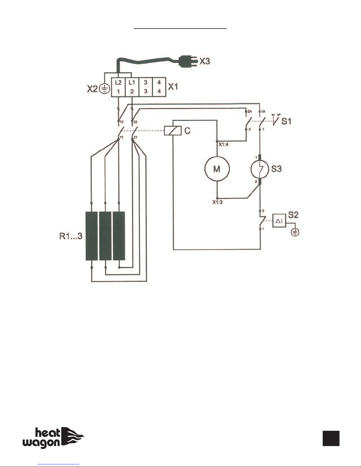
900 WIRING DIAGRAM
Key # Description Part#
C Contactor HWP 22570
M Fan Motor HWP 14201 (180014)
R1-R3 Heating Element HWP 42800
S1 Toggle Switch See Key #21 on page 11
S2 Ambient Thermostat HWP 20220
S3 Overheat Limit Switch HWP 21200
X1 Terminal Block HWP 36704
X2 Grounding Lug Not ncluded
X3 Power Cord & Plug ACC 50A10
Assembly
R1 R2 R3
12

1800-1, 1800-3, 1800D ARTS BREAKDOWN
13A
Key # Part# Description
1 HWP 180007 Bottom Plate
2 HWP 180006 Front Panel (P1800D - HWP 1800037)
3 HWP 180015 Rear Panel
4 HWP 180002 Hood* (No Hatch)
HWP 180032 Hood with Connection Hatch*
5 HWP 180032A Connection Hatch*
6 HWP 180003 nner Mantle ( ncluding Air Cone)
7 HWP 180009 Bracket
8 HWP 180019 Rear Grill (P1800D - HWP 1800035)
9 HWP 180005 Front Grill
10 HWP 180026 Heating Element (9 per Heater)
11 HWP 180022 Contactor
12 HWP 180021 Main Switch Assembly
13 HWP 180008 Overheat Limit Switch (Outer)
13A HWP 180024 Overheat Limit Switch ( nner)
14 HWP 180025 Unit Cooldown Switch
15 HWP 400018 Thermostat Knob
15 HWP 20577 Thermostat Knob
For P1800-1, S/N 1036 & Beyond
For P1800-3, S/N 3509 & Beyond
For P1800D, S/N 0031 & Beyond
16 HWP 37910 Plastic Bracket
17 HWP 180017 Ambient Thermostat
17 HWP 20220 Ambient Thermostat
For P1800-1, S/N 1036 & Beyond
For P1800-3, S/N 3509 & Beyond
For P1800D, S/N 0031 & Beyond
Key # Part# Description
18 HWP 82760 Plate Nut
19 HWP 36809 Guard Ring
20 HWP 401604 Gasket for Connection Hatch*
21 HWP 180014 Fan Motor (P1800D - 14350, ncludes Blade)
22 HWP 180033 Fan Hub (7mm Shaft) P1800-1, P1800-3 only
23 HWP 180012 Fan Blade P1800-1, P1800-3 only
24 HWP 180027 Circuit Breakers (P1800-1 Only)
25 HWP 180001 Handle
26 SFP S1500-105 Bracket for Terminal Block (P1800-1 Only)
28 HWP 180004 Gasket
29 HWP 36615 Terminal Block (P1800-1 Only) (Qty. 3)
30 HWP 36616 Locking Clamp (P1800-1 Only) (Qty. 2)
32 HWP 36703 Terminal Block (P1800-3 Only)
(HWP 180023B)
33 HWP 180011 Fan Hub Cap & Bolt
*Similar Equipped Models Only
Not Shown
ACC WD1225 Duct for P1800D (12”x25’ long)
HWP 1800036 Capacitor for #21, P1800D
HWP 1800038 Capacitor Holder
13
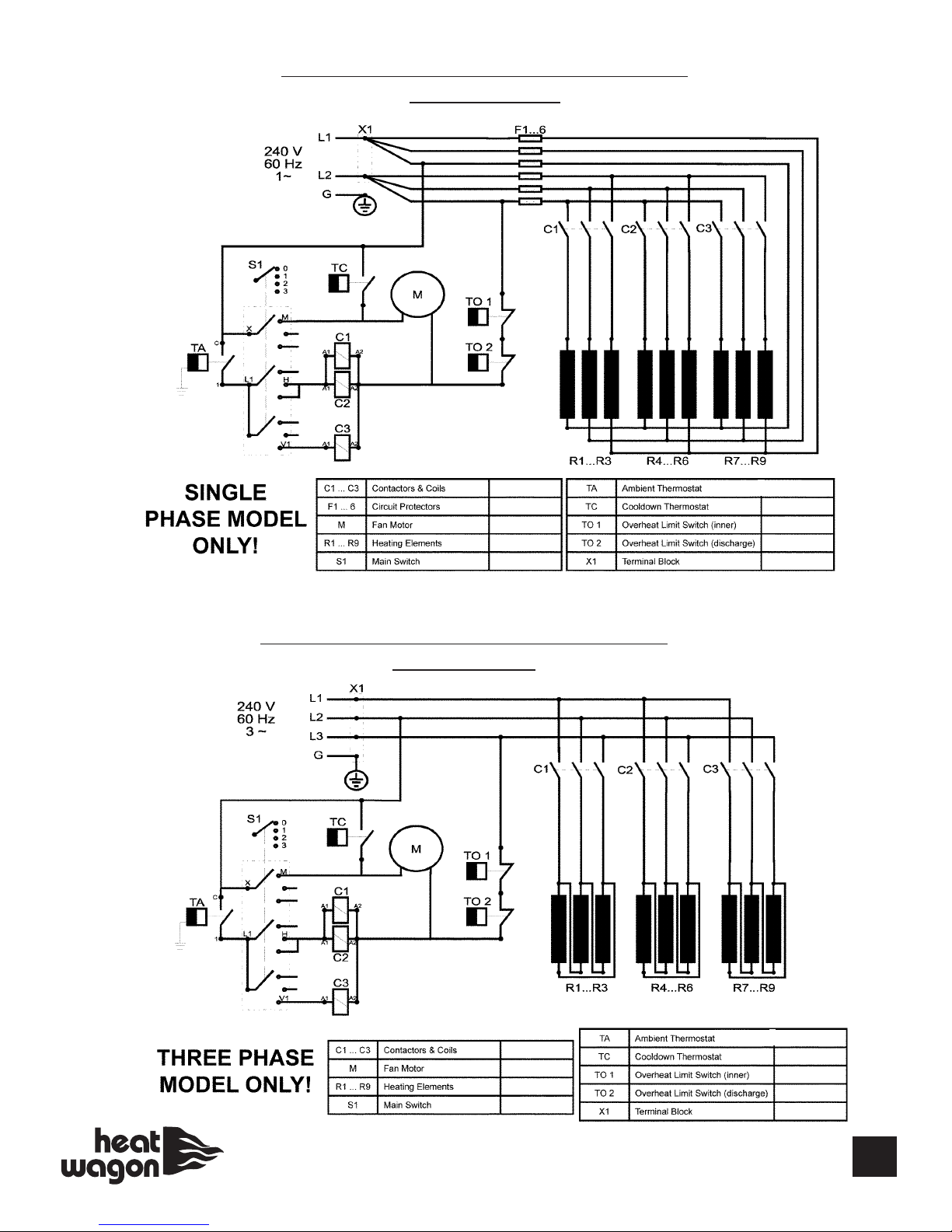
WIRING DIAGRAM HEAT WAGON 1800
THREE HASE
WIRING DIAGRAM HEAT WAGON 1800
SINGLE HASE
14
HWP 180022
HWP 180027
HWP 180014
HWP 180026
HWP 180021
HWP 180022
HWP 180014
HWP 180026
HWP 180021
See Part #17, P. 13
HWP 180025
HWP 180024
HWP 180008
HWP 36615
See Part #17, P. 13
HWP 180025
HWP 180024
HWP 180008
HWP 180023B

4000 - 6000 ARTS BREAKDOWN
15

4000 - 6000 ARTS BREAKDOWN
Key # Part# Description
1 HWP 400003 Heat Exchanger Chamber
4 HWP 400002 Hood ( ncluding Connection Hatch)
5HWP 400027 Connection Hatch Only
6 HWP 400001 Handle
7 HWP 400006 Front Panel
8 HWP 400008 Duct Adapter
9 HWP 400007 Bottom Frame
10 HWP 400011 Support Leg
11 HWP 400005 Wheel Shaft
13 HWP 180024 Overheat Limit Switch ( nner)
14 HWP 180025 Cooldown Thermostat
17 HWP 400004 Wheel
18 HWP 74600 Locking Washer
20 HWP 400026 Heating Element (15 Per Heater, P4000)
HWP 600026 Heating Element (15 Per Heater, P6000)
24 HWP 400015 Rear Panel
25 HWP 400009 Partition Panel / Bracket
26 HWP 400010 Contactor Mounting Plate
29 HWP 400019 Fan Guard Grill
30 HWP 400020 Bushing, Medium
31 HWP 400016 Bushing, large
33 HWP 400022 Contactor (4 Per Heater)
34 HWP 180016 Strain Reliever
35 HWP 400021 Toggle Switch
36 HWP 38110 Fuse Holder
36A HWP PEF1 Fuse
37 HWP 36615 Terminal Block (Qty. 3)
38 HWP 28400 Transformer (PETR)
39 HWP 36616 Locking Clamp + End Plate
40 HWP 37910 Plastic Bracket
41 HWP 180017 Ambient Thermostat
41 HWP 20220 Ambient Thermostat
For P4000, S/N 2022 & Beyond
For P6000, S/N 0531 & Beyond
42 HWP 400018 Thermostat Knob
42 HWP 20577 Thermostat Knob
For P4000, S/N 2022 & Beyond
For P6000, S/N 0531 & Beyond
45 HWP 400014 Fan Motor
47 HWP 400012 Fan Blade
48 HWP 36802 Bushing, Small
Not Shown
ACC WD1425 Duct for P4000, P6000 (14”x25’ long)
HWP 20550 Outlet Air Thermostat (PETE)
SFP S1500-105 Bracket for Terminal Block
16

17
4000 - 6000 CONTROL BOX
Item Part No. Description
1 See Part #41, P.16 AMB ENT THERMOSTAT
2 HWP 400022 CONTACTORS
3 HWP 400021 SW TCH
4 HWP 20550 OUTLET A R THERMOSTAT (PETE)
5 HWP 36615 TERM NAL BLOCK
6 HWP 28400 TRANSFORMER (PETR)
Item Part No. Description
7 HWP PEF1 FUSE
8 HWP 400026 HEAT NG ELEMENT - P4000
8 HWP 600026 HEAT NG ELEMENT - P6000
9 HWP 180024 OVERHEAT L M T SW TCH ( NNER)
10 HWP 180025 UN T COOLDOWN T-STAT
11 HWP 400014 FAN MOTOR
11
2
4
6
5
2
2
2
1
3
3
3
7
8
9
10
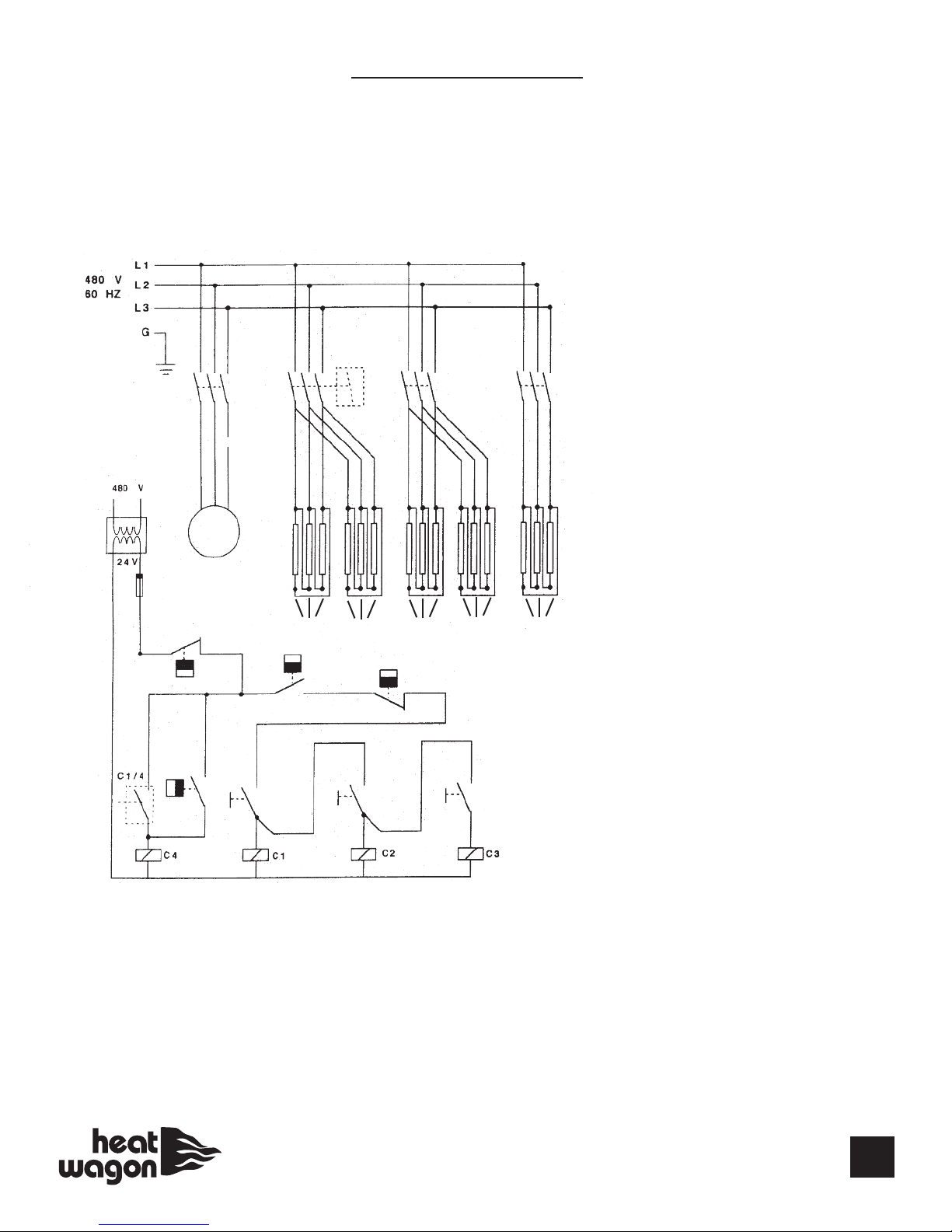
480 Volt 60 Hz 3 H
18
1
2
3
4
56
7
8910
11 12 13
14
15
16 16 16 16 16
Key # Part# Description
1 HWP 28400 Transformer
2 HWP PEF1 Fuse
3 HWP 400014 Fan Motor
4 HWP 180024 Overheat Limit Switch
5 HWP 180017 Ambient Thermostat
6 HWP 20550 (PETE) Limit Switch - Outer
7 HWP 180025 Unit Cooldown Switch
8 HWP 400021 Control Switch (for output 16KW)
9 HWP 400021 Control Switch (for output + 16KW)
10 HWP 400021 Control Switch (for output + 8KW)
11 HWP 400022 Contactor & Coil (for output 16KW)
12 HWP 400022 Contactor & Coil (for output + 16KW)
13 HWP 400022 Contactor & Coil (for output + 8KW)
14 HWP 400022 Fan Contractor
15 HWP 400022 Pole 4 of Contactor C1
16 HWP 400026 Heating Elements, 2.7KW each for P4000
16 HWP 600026 Heating Elements, 4.0KW each for P6000
4000 - 6000 WIRING

19
4000 - 6000 WIRING
This manual suits for next models
6
Table of contents
Other Heatwagon Electric Heater manuals

Popular Electric Heater manuals by other brands

Baxi
Baxi IVORY PEBBLE 800 Installer and owner guide

Frico
Frico Gliese Original instructions

Pahlen
Pahlen Aqua Compact Standart installation instructions

BN Thermic
BN Thermic WHE Series Installation and operating instructions

Varmebaronen
Varmebaronen EK 15 E Installation and Maintenance

Balboa Water Group
Balboa Water Group PERMAHEAT WHIRLPOOL BATH HEATER Information


