10
Värmebaronen EK 15E
Operation and maintenance
Before starting, check that the installation is in a
fullysatisfactory condition.
Ask the installation engineer to demonstrate
the controland functions so that you know how
thesystemworks and must be maintained.
Check:
• Boiler and heating system are filled with water,
ventedand that the pressure is correct.
• That all necessary valves are open.
• That any safety valves are working.
• That any external safety equipment is working
asintended.
• That the circulation pump is working and
theflowdirection is correct.
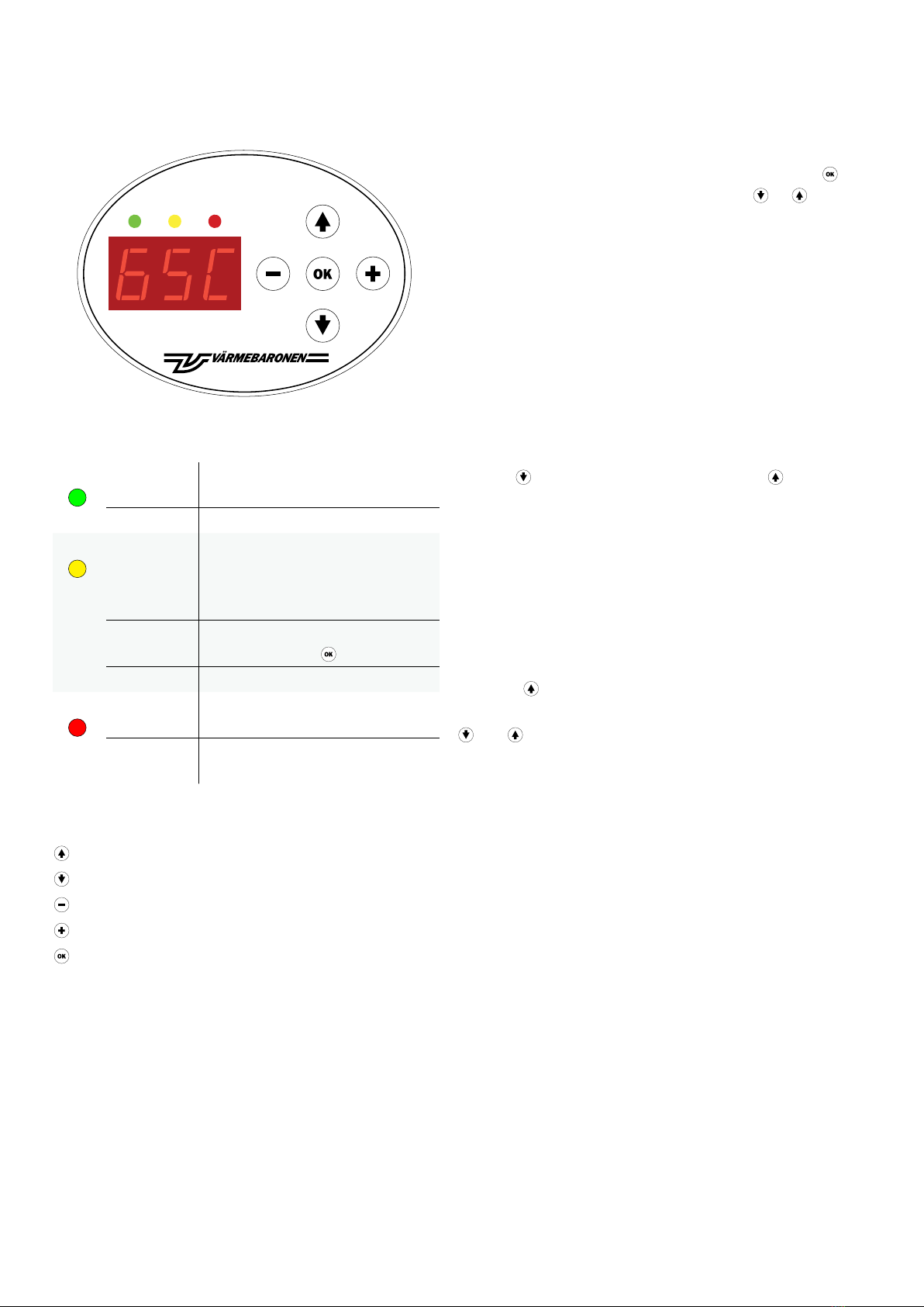
Start
Energised electric flow heater, the display illuminates
alongwith a green indicator.
A number of parameters are shown below that should
beconsidered when starting:
For installation/ configuration, see "Menu-
Management"!
• Stage restriction; "Service level" row 5.
• Load guard; "Service level" row 3.
• Circulation pump; "Advanced Service level"
rows20and23.
• External control/ Output control; "Advanced Service level"
row 13.
• ECO-mode; "User level" row 12.
Depending on whether the electric flow heater will be
controlled by a fixed or outdoor-compensated, UTK, setpoint.
For the UTK function, the electric flow heater must be
supplemented with an outdoor temperature sensor, optional.
• Desired boiler temperature; "User level" row 1.
• UTK; "Advanced service level" rows 5, 6, 7, 8 and 9
and"Service level" rows 6, 7 and 8.
• Room unit; "User level" rows 10 and 11 and
"Servicelevel"row 8.
The room unit is an option and requires that the
UTKfunction is activated.
Depending on the selected connection delay upon restart
after power failure, a connection delay can be applied for
output connection over 6kW, see "Advanced Service Level"
line 14.
For testing and service, the connection delay and
outputconnect/ disconnect can be temporarily sped up,
see"Service level" rows 1 and 2.
The electric flow heater should now step in the number
ofoutput stages needed until the temperature conforms
tothe set value.
Connection delay
According to the recommendations, a maximum of 6kW
ofthe output should be connected immediately after
avoltage loss.
See "Advanced Service level" row 14.
Circulation pump
Operating modes for circulation pump, see "Advanced
Service level" rows 20 and 23.
Load guard
The load guard protects the main fuses against overload
byreducing the electric flow heater's output. When the
overload ceases, the output is reconnected stage by stage.
See "Service level" row 3.
Stage restriction
The flow heater can be stage restricted in 1-7 stages.
Thenumber of stages selected corresponds to the installed
output. See "Service level" row 5.
Output limitation/ Output control, 0-10V
Output restriction; the electric flow heater's temperature
control is superior; the setpoint must be set slightly higher
than the required temperature.
Output control, only the overtemperature limit restricts. Used
together with another unit with its own temperature control.
See "Advanced Service level" row 13.
Desired boiler temperature
Desired boiler temperature, setpoint, see "User level" row 1.
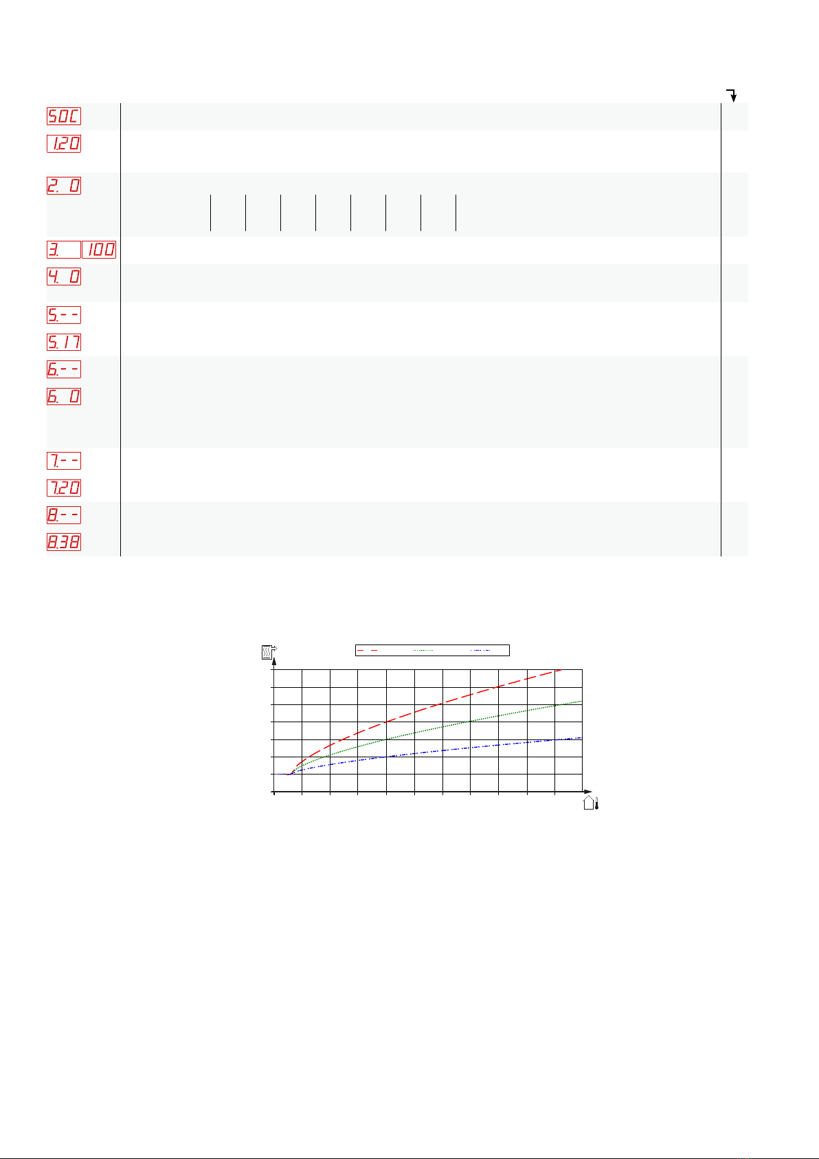
Outdoor temperature compensator setpoints, UTK
The Elomax electric flow heater must be supplemented with
an outdoor temperature sensor-option. This function must
beactivated in the menu system.
See "Advanced level" rows 5, 6, 7, 8 and 9 and "Service
level" rows 6, 7 and 8.
Alternative temperature
This function requires that the UTK function is activated and
an external contact. Can be used for night-time reduction,
holiday mode or similar, see "User level" rows 6 and 9.