Heckert Solar NeMo 4.1 80 M User manual
Installation and operating manual
PV-Module NeMo 4.1 80 M
www.heckert-solar.com
Status 08/2022
Standard 11 years
product warranty
Produced with
green energy
Made in Germany

www.heckert-solar.com
Version dated 07/2022
Installation and operating manual
This operating manual is addressed to suppliers, installers and operators of PV systems with monocrystalline high-
performance solar modules manufactured by Heckert Solar GmbH. It aims to ensure that the installed PV systems
produce optimum yields through the entire running time. Non-compliance may render the warranty invalid. Please read
the following instruction manual thoroughly.
Heckert Solar brand modules may only be installed by qualified specialist companies. Please observe the relevant
standards and regulations for the installation and operation of photovoltaic plants, such as VDE requirements, DIN
standards, the VDEW Guideline, the Technical Connection Conditions of the relevant network operators, as well as the
rules of the employers' liability insurance associations on accident prevention, in particular IEC 62446 on operation and
maintenance. Non-compliance may result in considerable personal injuries and material damage. The standards and
laws applicable in Germany form the basis of the information contained in this installation and operating manual.
This installation manual should form part of the plant documentation, and should be available to the plant operator at
any given time.
Heckert Solar reserves the right to amend the present document at any time without prior notice. Please use the most
current copy, which can be found on our homepage at
https://www.heckertsolar.com/service/
This installation and operating manual is in accordance with IEC 61730-1:2016.
Overview
1. Risks & safety precautions
2. General information on PV plants
3. Delivery & handling of the modules
4. Information on the module
5. Module installation
6. Connecting the modules
7. Returns & recycling
8. Product and service warranty
9. Disclaimer
1. Risks & safety precautions
Solar modules generate electricity as soon as they are exposed to light. It is hazardous to touch a module with a voltage
of 30 volts or more. Each serial or parallel connection of modules increases the voltage or current. By connecting more
than two solar modules in series, hazardous voltages may occur!
Danger of death due to electric shock!
Although touch protection is provided in the form of the fully insulated plug contacts, please ensure that when handling
the solar modules
no electrically conductive parts are inserted into the plugs or sockets!
solar modules and cables are not installed with wet plugs and sockets!
all works on the cables are undertaken with extreme caution!
high contact voltages may still be present inside the inverter even when the unit is switched off!
as a rule, caution is exercised when performing any work on the inverter and cables!
Heckert Solar brand modules correspond with Class II.
2
Risk of death by electric arc!
A deadly electric arc can result when opening a closed section (e.g. when separating the DC cable from the inverter
under load):
Never separate the solar generator from the invertor if the latter is connected to the grid!
Working on the roof
Please observe the applicable accident prevention regulations. Do not carry out installation work when there are strong
winds. Secure yourself and other persons from falling down. Prevent objects from potentially falling down. Secure the
work area so that no other persons can be injured.
2. General information on PV plants
Orientation
The solar module achieves the highest yield when oriented to the south (towards the north when in the southern
hemisphere). The optimum angle of inclination outside the tropics can be estimated using the following equation:
Angle of inclination = latitude of the installation site - 20°
Deviations from the optimum orientation and inclination of the modules lead to a reduction in yield.
The minimum inclination is 3°.
Angle of inclination >75° may lead to regional restrictions.
Location
The area planned for the installation should be as free as possible from shade of any kind (houses, trees, branches,
chimneys, dormers, antennas, satellite dishes, cables, etc.), because shade can significantly reduce the efficiency of the
solar modules. Core shadows should be avoided. Even partial shading will lead to a significant reduction in yield. A
module is considered “shade-free” when the entire surface is shade-free all year round and, even on the most
unfavourable days of the year when the sun is low, receives unobstructed sunlight for several hours.
Rear ventilation
The output of solar modules decreases considerably as the modules heat up. Rear ventilation avoids yield-impairing
heat accumulation. The so-called “chimney effect” (draught behind the modules) should not be impeded if possible
(e.g. roof windows, collectors).
Cleaning/Maintenance
With a sufficient inclination of the modules (>20°), there is a self-cleaning effect from rain and snow. Cleaning the
modules is generally unnecessary. In the case of a smaller inclination, the self-cleaning effect is only limited.
However, the soiling of the modules is strongly dependent on the surrounding environment and should be checked once
a year. In case of heavy soiling, it is recommended that the modules be cleaned after cooling down (e.g. in the morning)
using plenty of lukewarm, de-mineralised water and a gentle cleaning device, as sharp-edged items might lead to
scratches on the surface or to destruction of the anti-reflective (AR) coating. Clean, lint-free cotton, microfibre cloths
or paper towels should be used for cleaning. Fatty or oily deposits can be removed with isopropyl or isopropyl/water
mixtures. You should also refrain from using strong acids, alkalis, benzine-based cleaning agents or hot cleaning agents,
as well as cleaning agents containing silicone oil, fluorides or wax, polishes, alkaline cleaning agents and cleaning agents
with abrasive chemical products or high-pressure cleaners. Any methods, means or conditions which can exchange Na
ions from the glass surface are unsuitable for cleaning glass. All abrasive cleaning agents and utensils are also
unsuitable. Please note that too great differences in temperature can lead to tension in the glass, which may damage
the module.
If other cleaning methods or means are used, the anti-reflective coating may be damaged or become dirty down to the
pores, which can lead to visual changes and/or a loss of performance.
3
Please make sure that the earthing is not interrupted or destroyed when carrying out
cleaning and maintenance work!
3. Delivery & handling of the modules
The goods must be checked immediately upon delivery to ensure completeness and integrity. Only damages which are
noted on the driver’s delivery receipt and are immediately communicated in written form to Heckert Solar can be
recognised as transport damages.
In general, our brand modules are packed upright on a one-way pallet of up to 30 or max. 19 modules. Take care when
unpacking, transporting and storing the modules. We recommend keeping the modules in their packaging until ready
for installation. Always set the pallets on a reinforced level ground and do not stack them under any circumstances.
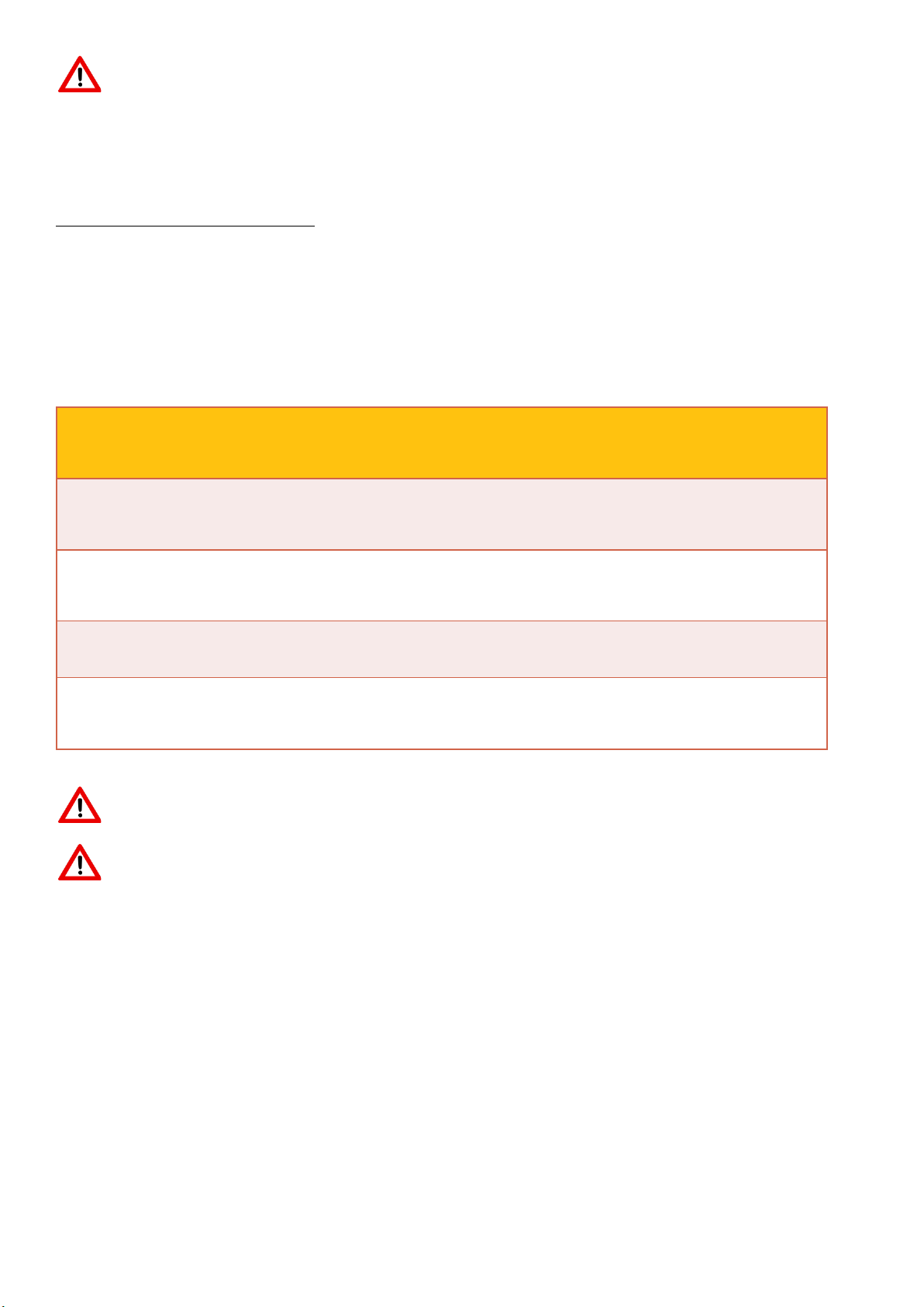
Standard
packaging
Picking
packaging
Number of modules/
pallets
20-30
1-19
External dimensions
(W x L x H)
1.2 m x 1.16 m x 1.94 m
1.2 m x 1.16 m x 1.94 m
Weight of full pallet
660 kg
430 kg
Quantity per truck
22 pallets * 30 modules = 660 pcs.
22 pallets * 19 modules = 18 pcs.
The packaging is not film-wrapped and is therefore not resistant to rain!
Please be sure to observe the unpacking instructions on the packaging! Never remove
the rear retaining strap from pallets with 30 modules!

4
Figure 1: Standard packaging: Pallet with 30 modules
Figure 2: Picking packaging: Pallet with 19 modules or fewer
Exercise caution when working with the modules!
Carry the modules with both hands. Do not use the connection sockets or cables(s) as a handle. During the
transport and installation, take care that no pressure or tension is exerted on connection sockets and cables.
Protect the modules from any hard knocks! Do not set the modules down roughly on hard ground. Do not set
the modules down on their corners. Do not place the modules on top of each other unprotected. Do not place
any objects on the modules. Never stand on the modules! Do not allow the modules to fall or use hard or
pointed objects on them.
Special care must be taken to connect the modules in accordance with the instructions and should not be
forced. Keep all electrical contacts clean and dry.
A dry, well-ventilated room should be used to store the modules.
For the system documentation, it is advisable to make a note of the serial number and address of the place of
installation on the installation plan.
Do not install any damaged modules.

5
Please observe the specific instructions for handling solar modules with AR glass.
Compared with non-coated glass, the surface of AR glass has a similar resistance to mechanical influences. The
resistance to corrosion and chemical influences is considerably higher than with non-coated glass. The AR layer should
be handled with the same care to avoid any damage to it. Due to its special reflective properties, light soiling is more
noticeable than on non-coated glass. In particular, fats/oils are visible even in small amounts and change the reflection
and thus also the appearance of the module. In order to avoid these marks, the modules should only be touched with
clean gloves or suction cups with covers.
4. Information on the module
Certification and Performance Data
For the performance data and instructions on certificates for our brand modules, please refer to the datasheets for
the respective series.
Use
Please observe the following points in particular for the use of our brand modules:
Installation or operation of the solar modules is permissible up to an altitude of max. 2000 m above sea level.
The function of the modules is tested at an ambient temperature of -40 to +40°C or an operating temperature
of -40 to +85°C. This area should be adhered to.
The solar module is not suitable for use in seawater.
When installing in salty air, functional earthing must be provided.
The module must not be subjected to unusual chemical loads (e.g. emissions from manufacturing plants).
Do not immerse the solar module in liquid.
Do not install the module in the immediate vicinity of air-conditioning units.
Do not use any lenses or mirrors to concentrate light (risk of overheating).
Avoid damage to the module from using carbide or diamonds.
Protect solar modules from overvoltage, e.g. voltage peaks from battery-charging devices, generators or
alternators etc. (Please ask your specialist retailer in case of any doubt).
If solar modules are connected to energy-storage devices, the safety instructions of the respective manufacturer
must be followed.
Keep children away from solar modules.
In southern regions, a PV module can supply greater power and/or a higher voltage than stated for the standardised
test conditions (standard test conditions). Therefore, to determine the voltage ratings of components, current ratings
of conductors, sizes of fuses connected to the output of PV modules, the values of Isc and Uos indicated on the module
should be multiplied by a factor of 1,25. The highest rated value for overcurrent protection (reverse current resistance)
is 20 A.
5. Module installation
General instructions on module installation
All modules can be fitted both horizontally and vertically independent of the connector sockets.
The modules must not be subject to stress during installation. The modules cannot be used as a rigid linking or fixing
element.
Please be advised that the holes in the frame and in the corners must remain free in order to allow condensed water
to flow out.
Load on the modules
The load capacity of standard solar modules is independent of the installation situation and the system used. Please
observe the installation situations in the following table and the resulting maximum load capacity of the modules.
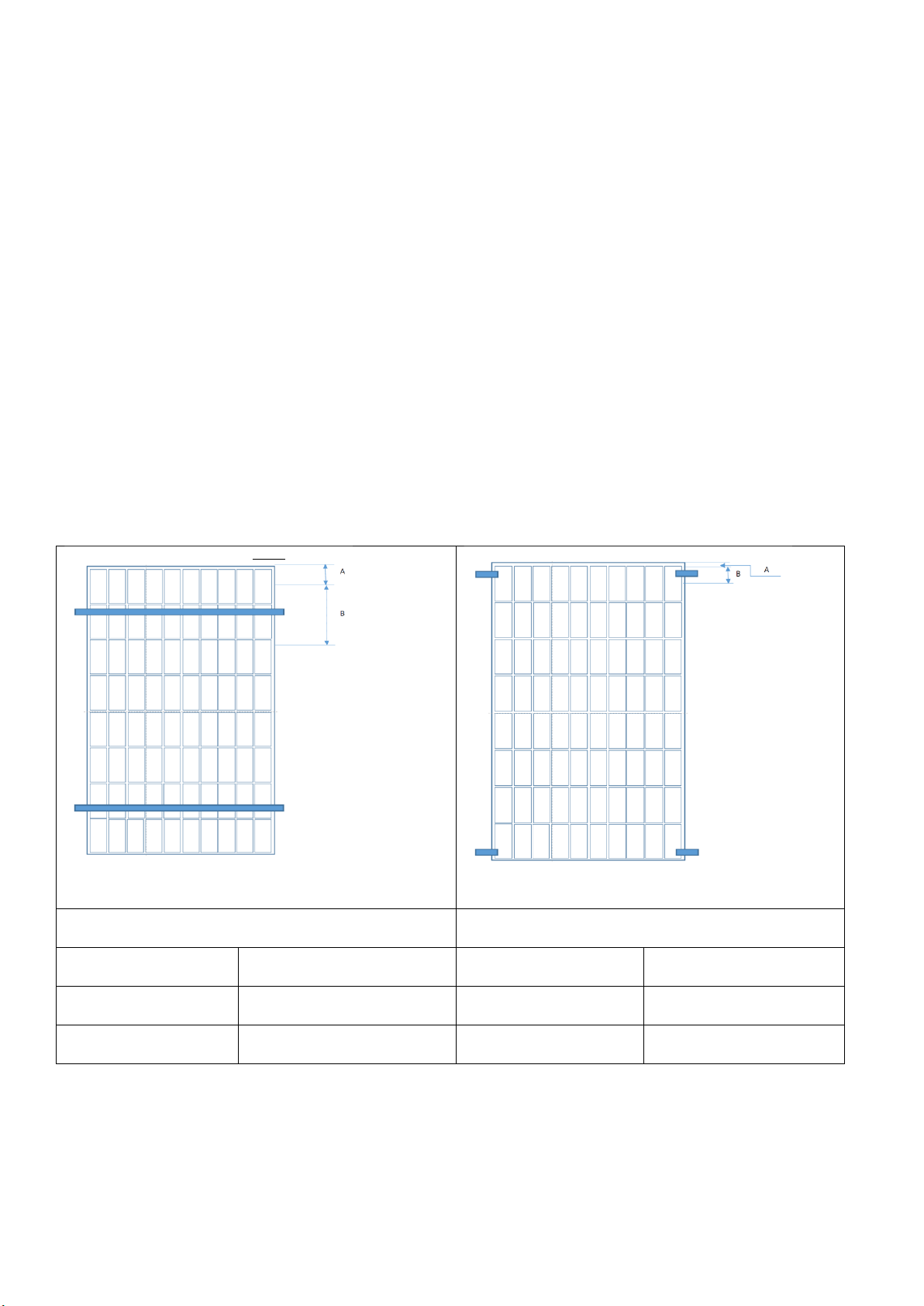
The values shown (Fig. 3) correspond to the design load in accordance with IEC 61215: 2016. The cyclical load test is
carried out according to the standard of a 1.5 times higher test load.
6
Default situation for continuous mounting rails
Please note that the module can bend under high loads and can strike the mounting rails. Ensure that the mounting rail
displays a sufficient stability and the fixing points are set with sufficient frequency to prevent the mounting rail from
bending. (tested with Heckert Solar rails and a support spacing of max. 1m)
Ensure that the maximum mechanical load is not exceeded, in particular while also taking into account the site-
dependent loads, e.g. wind and snow (DIN 1055-4/5).
Do not use any fixing material that might damage the module e.g. due to pointed, sharp or uneven structures. Please
note that the module bends under load and can strike the supporting surface/ mounting rails. Ensure that the connector
sockets and cables, when necessary, are not damaged or exert pressure on the cells.
The total snow load on the ground sk in kN/m² results from the respective snow load zone, the building site and the
ground height above sea level. The total wind load for the project site must be determined from the wind zone map,
which takes into account the site situation as well as wind zones. For buildings up to a height of 25 m, the total wind
load may be determined through a simplified procedure. Independent of building heights, the wind load is specified as
velocity pressure q in kN/m2.
2 continuous rails under module 4 fixing points
A = 250; B = 150
4 fixing points in the corners (internal clearance)
A = 10; B = 200
Test load
Design load
Test load
Design load
Pressure 6000 Pa
Pressure 4000 Pa
Pressure 2400 Pa
Pressure 1600 Pa
Suction 2400 Pa
Suction 1600 Pa
Suction 2400 Pa
Suction 1600 Pa

7
Positioned linearly on the long side
High load capacity with 3rd rail
A = 315; B = 868
The middle rail must run above the connector sockets,
cables go in the other direction
Test load
Design load
Test load
Design load
Pressure 3600 Pa
Pressure 2400 Pa
Pressure 8100 Pa
Pressure 5400 Pa
Suction 2400 Pa
Suction 1600 Pa
Suction 2400 Pa
Suction 1600 Pa
Clamp short side
A = 150; B = 150
4 fixing points in the corners (internal clearance)
A = 10; B = 200
Test load
Design load
Test load
Design load
Pressure 5400 Pa
Pressure 3600 Pa
Pressure 2400 Pa
Pressure 1600 Pa
Suction 2400 Pa
Suction 1600 Pa
Suction 2400 Pa
Suction 1600 Pa
Figure 3: Load capacity depending on the installation situation
8
The maximum load capacity of the modules can only be achieved by clamping the
specified area and complying with all conditions!
Please note that the planning and execution of the project is the sole responsibility of
the installation company, and in some cases, it is necessary to prepare property statics!
Load restraints
To prevent the modules from slipping on sloped surfaces during installation and to facilitate installation, our module
frames are fitted with holes for load restraints. Screws with hexagon socket head caps are fixed in these holes in the
module frame. The screws are fastened with a washer and nut or using a self-locking nut. An M5x10 VA screw and the
corresponding toothed washer and nut is recommended for the load restraints.
6. Connecting the modules
The solar modules from Heckert Solar are equipped with Original MC4 connectors (Stäubli –MultiContact)
Only connectors in accordance with DIN EN 62852 (VDE 0126-300) may be used.
Please note that only the proper tool may be used for the crimping of connectors.
Defective crimped connections may cause significant damage to the modules and could even cause the plant to burn
down.
The modules are connected to the strings in series. This adds the voltage of the modules to the string. Please note that
the permissible system voltage of 1000V may not be exceeded even at very low temperatures.
Please note that it is imperative to avoid tensile force on the connection cables.
Please note that only the manufacturer’s connectors may be connected. Even
“compatible” connectors can loosen the connection and cause an electric arc. This is
especially important to consider when using power optimizers!
Please ensure that the connectors are not in water for prolonged periods of time (cable
ducts, roof surfaces)!
Any change in the connector socket can lead to the warranty being rendered null and
void, and therefore may only be carried out by trained and skilled personnel.
No damaged modules may be installed!
Both connector sockets are fitted with a cable (900 mm in length) and connectors. The socket (+) is located on the
right-hand side, and the plug on the left-hand side (-) (Fig. 4). The connectors are each designed in such a way as not
to create confusion.

9
Figure 4: Configuration of the connector sockets
The individual solar modules in a string can be interconnected effortlessly.
Please ensure the correct connection of the plugs and sockets!
Figure 5: Connected MC4 modules
The string cables are connected to the MC4 connectors on the first or last module in the string.
The connectors comply with IEC 62852.
Please be sure to observe the requirements set out in DIN VDE 0298-3 for cable routing, in particular the smallest
permissible bending radii (Figure 6; R>5 x cable Ø) and the guidelines for cable fastening and routing.
Figure 6: Bending radii
10
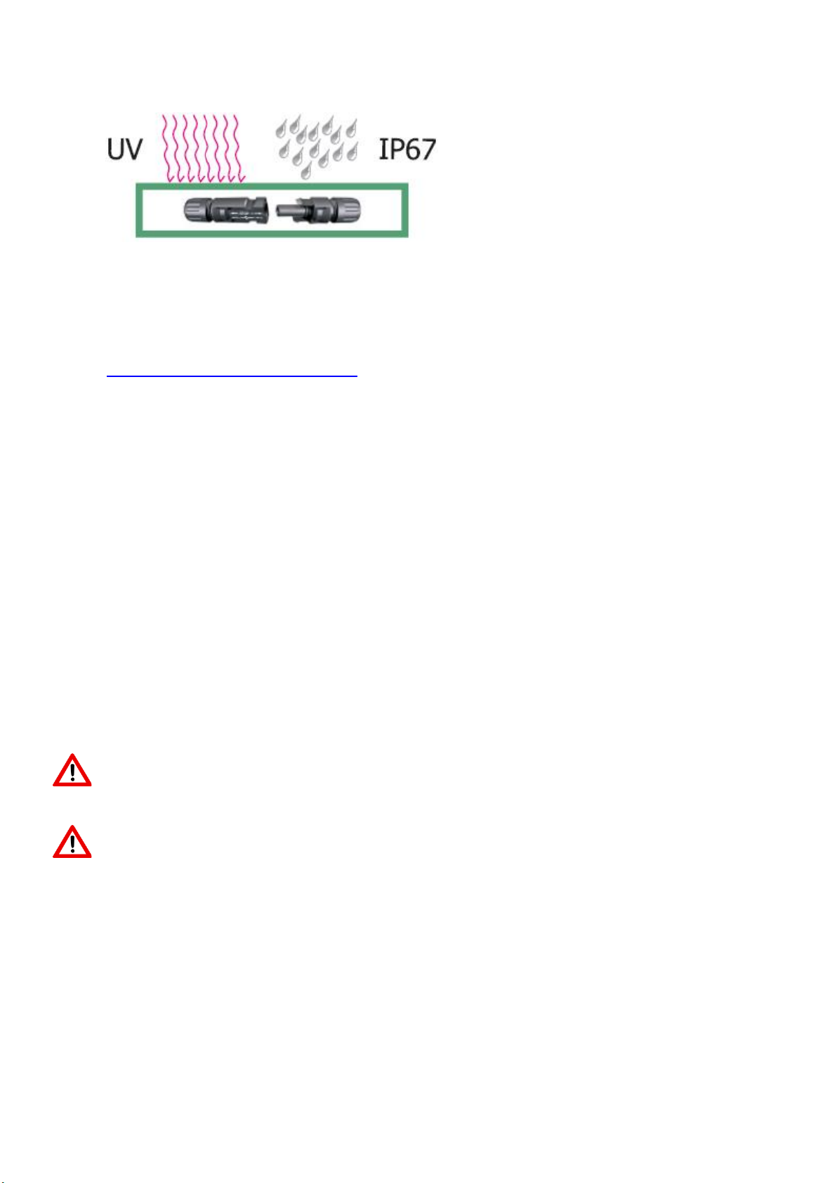
The connectors have a protection class of IP68 after connecting to the plug; the connector socket has a
protection class of IP65. Both components are permanently protected against environmental influences.
Figure 7: Protection class
Pleasure be sure to observe the instructions and installation instructions of the respective manufacturer. See
Annex. The Multicontact instructions can also be found on our homepage
(https://www.heckertsolar.com/service/).
Cable routing
Per string, 2 cables are required per string, that connect the solar generator to the inverter. Please use solar cables
that comply with the standard EN 50618 class 5 and the respective requirements. The minimum cross-section is
4mm². Cable losses should be < 1%. At greater distances, the cable cross-section must be adjusted accordingly.
Please be sure to observe the requirements set out in DIN VDE 0298-3 for cable routing.
The strings (+ and - cables) are fed into the inverter and connected to the DC inputs. The module connectors are
marked. To avoid conductor loops, the strings (+ and -) should be laid together.
When connecting the strings to the inverter, ensure that its polarity is correct. The + and - cables must not be
interchanged. Using a multimeter/voltmeter, the polarity and voltage of the individual strings should be verified before
connecting them to the inverter.
Only certified, suitable connectors are approved for the connection of the solar cables to the inverter. The installation
or connection of the inverters should be carried out in accordance with the manufacturer's instructions.
The inverter manufacturer’s instructions are binding.
Pleasure ensure that there is no tension when routing the cables and that the plug and
crimp are properly connected!
Depending on the module performance and inverter type, different length strings are
possible. Make absolutely sure that the permissible system voltage cannot be achieved
at full-load (VOC) and at low temperatures.
Parallel boarding of PV modules
When wiring our brand modules, it should be noted that string fuses (safety fuse 16 A) must be used for the parallel
boarding of more than 2 strings.
The maximum reverse current load capacity is 25 A. Where more than two strings are connected in parallel, this may
be exceeded in the case of a fault.
11
Electrical installation
Connection of the inverter to the public electricity network must be carried out by an authorised specialised company.
Even at low solar radiation, there is high DC voltage. Never touch unprotected + and -
cables that are in operation!
Equipotential bonding
The requirements for the lightning and surge protection are dependent on the local conditions. Where there is already
an external lightning protection system in place or planned for the building, the PV system must be integrated in the
protection system against a direct lightning strike.
When using transformer-less inverters, due to the galvanic isolation, equipotential bonding may be required for reasons
of personal safety. Country-specific laws shall apply.
The responsibility for a professional equipotential bonding of the module frame lies with the installing company. Country-
specific standards must be adhered to.
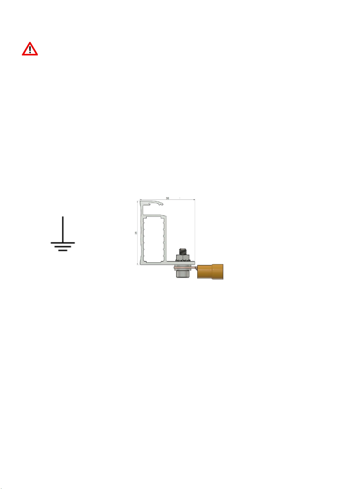
A hole is drilled in the middle of the short sides of the module frame for equipotential bonding, and is marked with the
corresponding symbol (Figure 8).
An M4 screw is required for equipotential bonding. The fixing must be carried out using a spring washer or toothed
washer to ensure that the anodized layer is penetrated.
Figure 8: Equipotential bonding symbol and execution
Functional earthing
Functional earthing is required in the following cases:
-installation in tropical regions (23.5°N –23.5°S)
-Module inclination <5°
-Installation near the sea
It must be ensured with functional earthing that the voltage difference between the negative generator pole and earth
potential (substructure, protective earth PE of the inverter) is ≥0V on the individual strings in operating mode.
Please observe the inverter manufacturer’s installation instructions. Only earthing kits approved by the manufacturer
may be used
Fire protection
The installation of on-roof systems can affect the fire safety of a building; improper installations can result in a hazard
in case of fire. Please observe LBO Building Law requirements. In the event of on-roof systems, the Heckert Solar brand
modules must be installed above a fire-resistant surface (“hard roofing” in accordance with DIN 4102-4). The module
is “non-explosion-proof operating equipment”. It may not be installed near highly-flammable gasses and vapours (e.g.
petrol stations, gas containers or spraying systems). The module may not be installed near open flame or flammable
materials.
-Cable clamp
-Screw
-Toothed washer
-Nut

12
The Heckert Solar modules were verified for their fire behaviour in accordance with IEC 61730-1:2004 und ISO 11525-
2:2014. Our modules are considered to be flame retardant (Fire-resistance class C). Heckert Solar does not accept any
warranty claims for inadequate supporting surfaces, in particular roof covering.
A clear labelling of the PV system and installation diagram, on the domestic junction box and the main building
distribution board, are normative.
7. Returns & recycling
Returns & recycling of solar modules are governed by the WEEE ElektroG2 Directive. Please observe country-specific
regulations. Where applicable, notification may be required in the respective country.
EAR registration number DE42676826
8. Product and service warranty
Information and terms for our product and service warranties can be found on our homepage under www.heckert-
solar.com .
9. Disclaimer
These installation and operating instructions apply to general installations. All information is supplied without guarantee.
Heckert Solar GmbH shall assume no liability for the usability and functionality of the system if there are deviations from
the instructions contained in this user information. Given that neither compliance with this user information, nor the
conditions, use and methods of installation, nor system operation, nor maintenance of the modules can be checked or
monitored by Heckert Solar GmbH, the latter shall assume no liability for damage resulting from unintended use,
incorrect installation, operation, use or maintenance.
Moreover, liability for patent infringements or infringements of other third-party rights resulting from the use of the
modules is excluded unless liability is mandatory by law.
Our technical service department would be happy to answer any other questions you may have and can be reached at:
+49(0)371/458568-0.
Annex: Assembly instructions MC4 connector (Stäubli)
Heckert Solar GmbH • Carl-von-Bach-Straße 11 • D-09116 Chemnitz
13
Excerpt from MC4 crimping instructions (Source: Multi-contact)
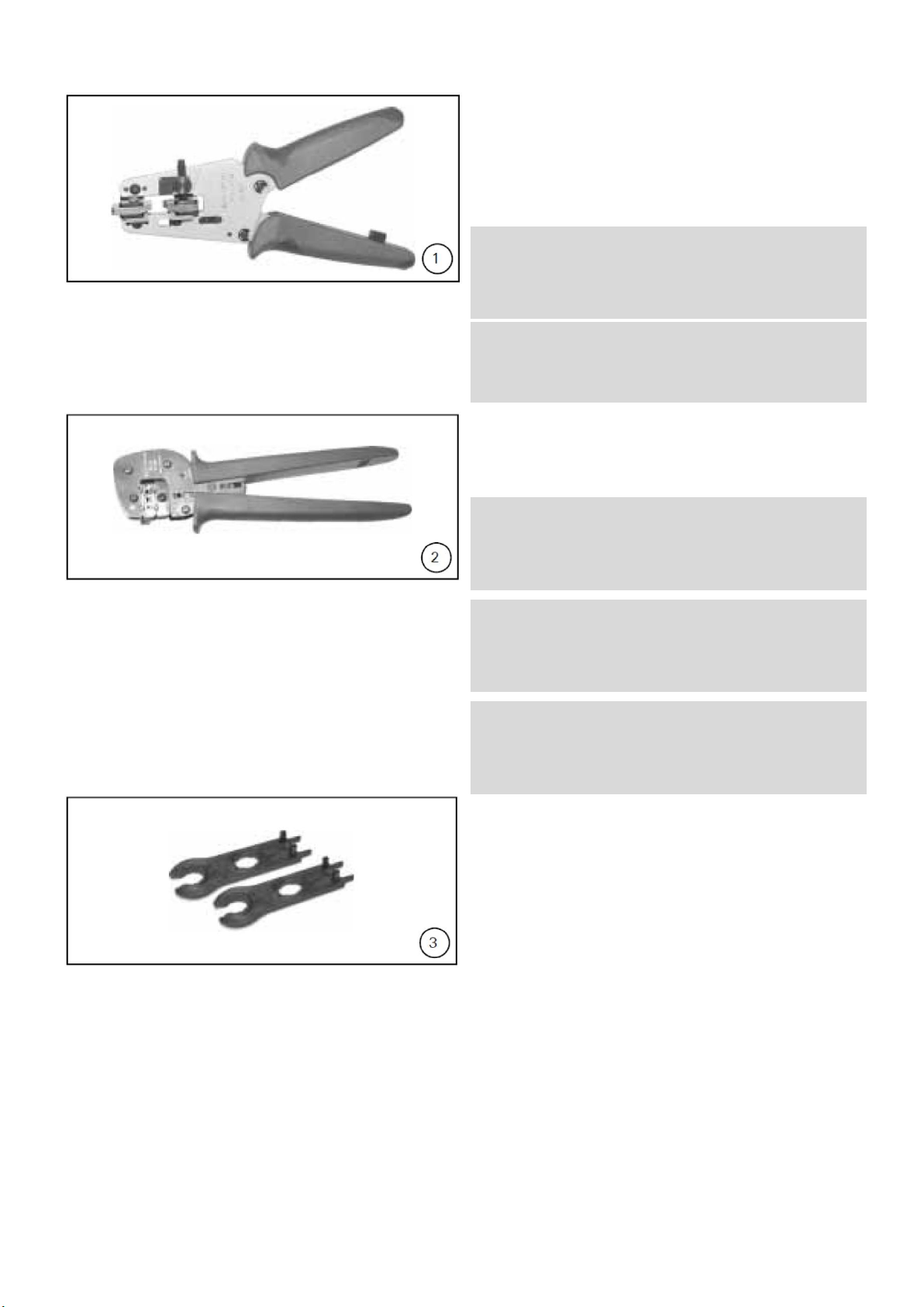
Required tool
(ill. 1
Stripping pliers PV-AZM... incl built-in
stripping blades and hexagonal spanner,
width across flats 2.5.
Conductor cross-section 1.5 / 2.5 / 4 /
6mm2
Type: PV-AZM-1.5/6
Order no. 32.6029-156
Conductor cross-section 4 / 6 / IO mm2
Type: PV-AZM-4/I0
Order no. 32.6027-410
(ill. 2)
Crimping pliers PV-CZM... incl. locator
and built-in crimping insert.
Crimping range:
1.5/2.5/4 mm2 (14/12 AWG)
Type: PV-CZM-18100
Order no. 32.6020-18100
Crimping range:
2.5/4/6 mm2 (12/10 AWG)
Type: PV-CZM-19100
Order no. 32.6020-19100
Crimping range:
4/IOmm2(12 AWG)
Type: PV-CZM-20100
Order no. 32.6020-20100
(ill. 3)
PV-MS construction spanner. I Set = 2
pieces
Order no.: 32.6024
14
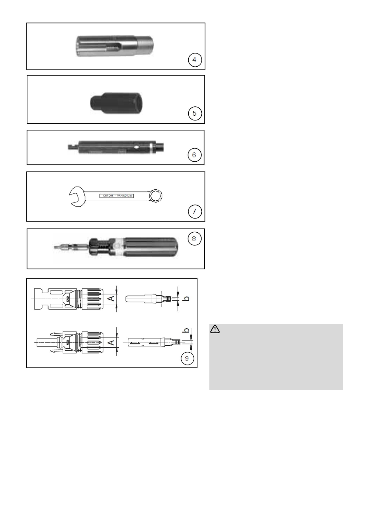
(ill. 4)
PV-WZ-AD/GWD socket spanner
for tightening Order no. 32.6006
(ill. 5)
PV-SSE-AD4 socket spanner for
countering
Order no. 32.6026
(ill. 6)
PV-PST test pin Order no. 32.6028
(ill. 7)
SW 15 Open-ended spanner
(ill. 8)
SW 12 Torque wrench
Preparing the line
Connecting lines with a stranded
wire construction of classes 5 and 6
can be connected.
Warning:
Do not use bare or already
oxidised conductors. Tin-plated
conductors are advantageous.
All solar cables from MC have
high-quality, tin-plated
conductors.
(ill. 9, Tab. 1)
Check the dimensions A and b
according to illustration 9 and table
I.

15
Tab. 1
b Kontrollmass
b- Control dimension
Leitungsquerschnitt
Conductor cross section
A: Ø -Bereich Leitung / A: Ø Range of cable
mm
3.0 –6.0
5.5 –9.0
mm
Mm2
AWG
Typ / Type
~ 3
1.5 –2.5
14
PV-K...T4/...2.5l
PV-K...T4/...2.5ll
~ 5
4 –6
12 / 10
PV-K...T4/...6l
PV-K...T4/...6ll
~ 7.2
10
-
PV-K...T4/...10ll
(ill. 10)
Strip the cable.
Remove the insulation of the cable over
a length of 6.0 to 7.5 mm.
Warning:
Do not cut any individual wires when
stripping!
Note:
1 In order to use the stripping pliers
PV-AZM... and replace the sets of
blades, please refer to the operating
instructions MA267 at www.multi-
contact.com
Crimping
(ill. 11)
Open the clamping bracket (K) and hold it
firmly. Place the contact in the
appropriate cross-section area. Turn the
crimping lugs upwards. Release the
clamping bracket (K). The contact is now
fixed.
16
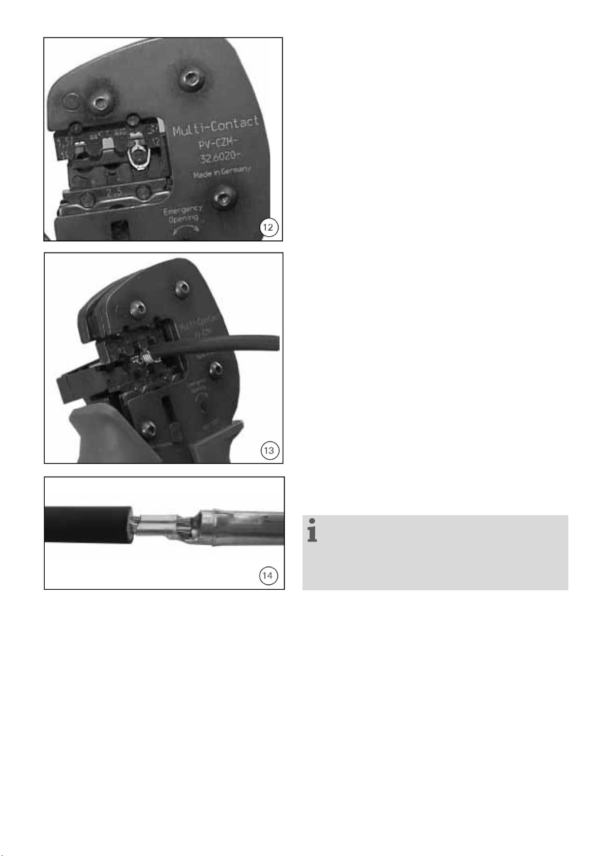
(ill. 12)
Gently squeeze the pliers together until the
crimping lugs are securely inside the crimp
die.
(ill. 13)
Insert the stripped cable. until the insulation
touches the crimp insert. Close the
crimping pliers completely.
(ill. 14)
Visually check the crimping.
Note:
please refer to the operating instructions
MA251 at www.multi-contact.com for
information on how to use the crimping pliers.

17
Mounting inspection
(ill. 15)
Insert the crimped contact from behind into
the plug or socket insulation until it
engages. Check that the metal part is
properly engaged by pulling gently on the
cable.
(ill. 16)
Insert the test pin with the corresponding
side into the socket or plug as far as it will
go. When the contact is correctly mounted,
the white marking on the test pin must still
be visible.
(ill. 17)
Hand-tighten the cable gland with the PV-
MS tools
or
tighten the cable gland with the PV-WZ-
AD/ GWD and PV-SSE-AD4 tools.
In both cases,
the tightening torque must be adjusted to
the specific solar cables used. Typical
values are in the range from 2.5Nm to
3Nm.
Plugging and unplugging the cable
coupling without securing sleeve PV-
SSH4
Plugging
(ill. 18)
Plug the cable coupling together until it
engages. Check that it engages correctly
by pulling on the cable coupling.

18
Unplugging
(ill. 19)
To unplug the contacts, press the
engagement tabs (X) together either by
hand or with the PV-MS tool and pull the
cable coupling apart.
Plugging and unplugging the cable
coupling without securing sleeve
PV-SSH4
Plugging
(ill. 20)
Plug the cable coupling together until it
engages. Check that it engages correctly
by pulling on the cable coupling.
Unplugging
The cable coupling can only be unplugged
with the PV-MS tool. Press the
engagement tabs (X) together with the PV-
MS tool and pull the cable coupling apart.
von Hand
by hand
mit PV-MS
with PV-MS
This manual suits for next models
1
Table of contents
Other Heckert Solar Solar Panel manuals


Popular Solar Panel manuals by other brands


SFC Energy
SFC Energy XTREMESOLAR XTR-S290P Series installation manual

OURASET
OURASET ECOSET 151 instruction manual

Westinghouse
Westinghouse AC System installation guide

ECO-WORTHY
ECO-WORTHY 100W Installation

King Pigeon
King Pigeon SLP1210-P instruction manual

Wolf
Wolf CFK-1 Installation, operating and maintenance instructions

Segway
Segway SP-100 user manual

REC
REC REC320NP installation instructions

UNIRAC
UNIRAC PoleTops 5001 Series installation manual

Southwest Windpower
Southwest Windpower Skystream Hybrid 6 installation manual

Schletter
Schletter SECT installation manual

solarwatt
solarwatt Vision 60P style installation instructions