Heckert Solar NeMo P Standard User manual

Installations- und Bedienungsanleitung
Installation and Operating Instructions
Instructions d’installation et de service

August 2011 2Heckert Solar AG | Carl-von-Bach-Str. 11 | 09116 Chemnitz
Diese Anleitung wendet sich an Händler und
Installateure, die sich mit der Planung, Ins-
tallation und dem Betrieb von PV-Anlagen
mit polykristallinen oder monokristallinen
Hochleistungs-Solarmodulen aus der Ferti-
gung der Heckert Solar AG befassen. Sie soll
Ihnen wertvolle Hinweise geben, um zu ge-
währleisten, dass die installierte PV-Anlage
über die gesamte Laufzeit optimale Erträge
erzielt. Heckert Solar Markenmodule wer-
den ausschließlich in Deutschland gefertigt
und zählen zu den weltweit hochwertigsten
PV-Modulen. Sie zeichnen sich durch ihre
sehr gute Verarbeitung und Langzeitstabili-
tät aus.
Heckert Solar Markenmodule dürfen nur
durch qualifizierte Fachfirmen montiert
werden. Bitte beachten Sie die für photo-
voltaische Anlagen relevanten Normen und
Vorschriften, wie z.B. VDE-Bestimmungen,
DIN-Normen, VDEW-Richtlinie, die TAB der
zuständigen Netzbetreiber sowie die Regeln
der Berufsgenossenschaften zum Unfall-
schutz. Die Nichteinhaltung kann zu erheb-
lichen Personen- und Sachschäden führen.
Grundlage für unsere Angaben in dieser
Installations- und Betriebsanleitung bilden
die in Deutschland geltenden Normen und
Gesetze. Die nachfolgenden Ausführungen
sind Empfehlungen, die Ihnen helfen sollen,
Heckert Solar Markenmodule ordnungs-
gemäß und problemlos zu installieren. Bei
individuellen Besonderheiten sollten Sie in
jedem Fall eine fachkundige Klärung herbei-
führen, um den Anforderungen des Daches
Rechnung zu tragen.
Bewahren Sie diese Anleitung zusammen
mit den anderen Anlagenunterlagen gut
auf!
Diese Installations- und Betriebsanleitung
befindet sich gemäß TÜV Rheinland in Über-
stimmung mit dem Sicherheitszertifikat IEC
61730, Teil 1.
Installations- und
Betriebsanleitung
These instructions are reference for dealers
and fitters who work with the planning, in-
stallation and operating of PV appliances
with polycrystalline and mono-crystalline
high performance solar modules manufac-
tured by the company Heckert Solar AG.
They should supply valuable information to
guarantee that the installed PV appliance
achieves an optimal output for the complete
service lifetime. Heckert Solar Brand product
modules are manufactured exclusively in
Germany and considered to be amongst the
highest quality PV modules worldwide. They
distinguish themselves by their very good
workmanship and long-term stability.
Heckert Solar brand modules may only be
installed by qualified specialist companies.
Please always take the relevant standards
and regulations for photovoltaic appliances
into consideration, such as for example VDE
regulations, DIN standards, VDEW guideli-
nes, the Respective network operators TAB
as well as the regulations from the profes-
sional association for accident prevention.
Non-compliance can lead to considerable
injury to persons and damage to assets.
The principles for the instructions in these
installation and operating instructions are
based upon the appropriate and applicable
German standards and laws.
The following explanations are recommen-
dations, which should assist you in the cor-
rect and problem free installation of Heckert
Solar Brand product modules. You should
always work out a competent solution for
individual specific features to calculate the
best possible considerations from the roof.
Safely save these instructions along with the
other appliance documentation!
These installation and operating instruc-
tions comply with the requirements of the
TÜV Rheinland (Technical Control Board Rhi-
neland) found in the safety certification IEC
61730, part 1.
Installation and
Operating Instructions
Ces instructions s’adressent aux commer-
çants et aux installateurs qui travaillent à
la conception, à l’installation et au service
des installations PV à modules solaires de
haute performance polycristallins ou mo-
nocristallins de fabrication Heckert Solar
AG. Elles ont pour objectif de fournir de
précieuses consignes dans le but de garan-
tir que l’installation PV produise un rende-
ment optimal pendant toute sa durée de vie.
Les modules de marque Heckert Solar sont
exclusivement fabriqués en Allemagne et
comptent parmi les modules PV de meilleure
qualité au monde. Ils se distinguent par leur
excellente finition et leur stabilité durable.
Les modules de marque Heckert Solar ne
doivent être montés que par des entreprises
spécialisées. Veuillez observer les normes
et règlements significatifs pour les instal-
lations photovoltaïques, comme par exem-
ple les dispositions VDE, les normes DIN, la
directive VDEW, les TAB des exploitants de
réseau compétents ainsi que les règlements
des corporations professionnelles pour la
protection des accidents. Un non respect
peut provoquer des dommages corporels et
matériels considérables. Les normes et lois
applicables en Allemagne sont à la base des
informations fournies dans nos instructions
d’installation et de service.
Les explications suivantes sont des recom-
mandations qui doivent vous aider à instal-
ler les modules de marque Heckert Solar de
manière conforme et sans problème. En cas
de particularités individuelles, vous devez
dans tous les cas rechercher la clarification
d’un expert pour tenir compte des exigences
du toit.
Conservez soigneusement ces instructions
avec les autres documents de l’installation!
Ces instructions d’installation et de service
sont en accord avec le certificat de sécurité
IEC 61730, partie 1 conformément au TÜV
Rheinland.
Instructions d’installation
et de service

August 2011 3Heckert Solar AG | Carl-von-Bach-Str. 11 | 09116 Chemnitz
Übersicht
1. Gefahren- & Sicherheitshinweise
2. Allgemeine Hinweise zu PV-Anlagen
3. Anlieferung & Behandlung der Module
4. Hinweise zum Modul
5. Modulmontage
6. Verbinden und Anschluß der Module
7. Rücknahme & Recycling
8. Produkt- und Leistungsgewährleistung
9. Haftungsausschluss
Overview
1. Danger and safety instructions
2. General information to PV installations
3. Delivery and handling of the modules
4. Notifications concerning the module
5. Module installation
6. Connection and coupling of the modu-
les
7. Return & Recycling
8. Product and performance guarantee
9. Exclusion of liability
Vue d‘ensemble
1. Consignes de danger & de sécurité
2. Consignes générales sur les installati-
ons PV
3. Livraison & traitement des modules
4. Consignes sur le module
5. Montage des modules
6. Raccordement et branchement des mo-
dules
7. Reprise & recyclage
8. Garantie produit et prestation
9. Exclusion de responsabilité
NeMo® P | Standard NeMo® P | Black Edition
HS P SOLRIF® NeMo® P Laminat
August 2011 4Heckert Solar AG | Carl-von-Bach-Str. 11 | 09116 Chemnitz
Solarmodule erzeugen Strom, sobald sie
Licht ausgesetzt werden. Eine Spannung von
30 Volt und darüber stellt bei Berührung eine
Gefahr dar. Jede Reihen- oder Parallelschal-
tung von Modulen erhöht die Spannung
bzw. Stromstärke. Bei Reihenschaltung von
mehr als zwei Solarmodulen können bereits
lebensgefährliche Spannungen entstehen!
ACHTUNG: Lebensgefahr durch Strom-
schlag!
Durch die vollisolierten Steckkontakte ist
zwar ein Berührungsschutz gegeben. Achten
Sie dennoch beim Umgang mit Solarmodu-
len darauf, dass
• Sie keine elektrisch leitenden Teile in die
Stecker und Buchsen einführen!
• Sie Solarmodule und Leitungen nicht
mit nassen Steckern und Buchsen mon-
tieren!
• Sie alle Arbeiten an den Leitungen mit
äußerster Vorsicht vornehmen!
• im Wechselrichter auch im freigeschal-
teten Zustand hohe Berührungsspan-
nungen auftreten können!
• bei allen Arbeiten am Wechselrichter
und Leitungen grundsätzlich Vorsicht
geboten ist!
Heckert Solar Markenmodule sind für den
Gebrauch der Anwendungsklasse A bemes-
sen: Anlagen gefährlicher Leistungen (>
240W), bei denen generell uneingeschränk-
te Zugänglichkeit zu erwarten ist, mit ge-
fährlichen Spannungen (IEC 61730: > 50V
DC; EN61730: > 120V DC). Module, die für
die Sicherheit durch EN IEC 61730-1 und
61730-2 innerhalb dieser Anwendungsklas-
sen qualifiziert sind, entsprechen den Anfor-
derungen der Schutzklasse II.
ACHTUNG: Lebensgefahr durch Lichtbo-
gen!
Bei der Öffnung eines geschlossenen Stran-
ges (z.B. beim Trennen der Gleichstromlei-
tung vom Wechselrichter unter Last) kann
ein tödlicher Lichtbogen entstehen:
1. Gefahren- &
Sicherheitshinweise
Solar modules start to generate electricity
as soon as they are exposed to light. It is
hazardous to touch a module with a voltage
of 30 volts or more. Every series or parallel
connection of the modules increases the vol-
tage or electric current, respectively. Series
connections of more than two solar modu-
lescan generate dangerous voltage: High
voltage!
ATTENTION: Danger to life through elec-
tric shocks!
Although the fully insulated plug-in con-
tacts do provide contact protection, you
should nevertheless observe the following
when handling solar modules:
• Do not insert electrically conductive
parts into the plugs and sockets!
• Do not install solar modules and wiring
with wet plugs and sockets!
• Exercise extreme caution when carrying
out any work on the wiring!
• High contact voltages can occur in the in
verter even when it is isolated!
• Always exercise caution during all work
on the inverter and the wiring!
Heckert Solar Brand product modules are for
designed for utilization under application
class A: Appliances with dangerous electrical
power (> 240W), for which unlimited acces-
sibility is to be expected, with dangerous
voltages (IEC 61730: > 50V DC; EN61730: >
120V DC). Modules, which qualify for the
safety requirements through EN IEC 61730-1
and 61730-2 within these applications clas-
ses, require the protective requirements of
protection class II.
ATTENTION: Danger to life through elec-
trical arcing!
A deadly electric arc can result when ope-
ning a closed section (e.g. when separating
the DC cable from the inverter under load):
1. Danger and safety
instructions
Dès qu’ils sont exposés à la lumière, les mo-
dules solaires génèrent de l’électricité. Au
contact, une tension de 30 V et plus consti-
tue un danger. Toute connexion en série ou
en parallèle des modules augmente la tensi-
on et/ou l’intensité du courant. La connexi-
on en série de plus de deux modules solaires
peut déjà produire des tensions dangereuses
pour la vie : Haute tension!
ATTENTION: Danger de mort par déchar-
ge électrique!
Même si les contacts à fiches entièrement
isolés assurent une protection contre les
contacts accidentels, il importe d’observer
les éléments suivants lors de la manutention
des modules solaires :
• Ne pas introduire des pièces électrocon-
duc trices dans les connecteurs et les
douilles!
• Ne pas monter les modules solaires et
les lignes avec des connecteurs et des
douilles mouillés!
• Effectuer tous les travaux sur les lignes
avec la plus grande prudence!
• Faire attention au fait que des tensions
de contact élevées peuvent se produire
au sein de l’onduleur même si celui-ci est
dé connecté!
• Effectuer impérativement tous les tra-
vaux sur l’onduleur et sur les lignes avec
la plus grande précaution!
Les modules de marque Heckert Solar sont
dimensionnés pour la classe d’utilisation A:
Les installations de puissances dangereuses
(> 240 W) pour lesquelles un accès illimité
est généralement à attendre, aux tensions
dangereuses (IEC 61730: > 50V CC; EN 61730:
> 120 V CC). Les modules qualifiés pour la sé-
curité par EN IEC 61730-1 et 61730-2 au sein
de ces classes d‘utilisation répondent aux
exigences de la classe de protection II.
ATTENTION: Danger de mort par arc élec-
trique!
1. Consignes de danger &
de sécurité

August 2011 5Heckert Solar AG | Carl-von-Bach-Str. 11 | 09116 Chemnitz
• Trennen Sie niemals den Solargenerator
vom Wechselrichter, solange dieser mit
dem Netz verbunden ist!
• Never disconnect the solar generator
from the inverter as long as it is connec-
ted to the grid!
En ouvrant un string fermé (par exemple,
en séparant la ligne à courant continu de
l’onduleur sous charge), on risque de créer
un arc électrique mortel:
• Ne jamais séparer le générateur solaire
de l’onduleur tant que le dernier est rac-
cordé au réseau!
2. Allgemeine Hinweise zu
PV-Anlagen
Leistungsdaten
Die Leistung unserer Markenmodule ent-
nehmen Sie bitte den Datenblättern der je-
weiligen Serie.
Ausrichtung
Das Solarmodul sollte möglichst nach Süden
ausgerichtet werden. Dies bewirkt die beste
Stromausbeute. Alternativ können Sie das
Solarmodul der Sonne nachführen. Die Nei-
gung der Module sollte mindestens 15° be-
tragen. Der optimale Neigungswinkel kann
nach folgender Formel berechnet werden:
Neigungswinkel = Breitengrad des Aufstel-
lungsortes -20°.
Standort
Die für die Installation vorgesehene Fläche
sollte möglichst frei von Verschattungen
jeglicher Art (Häuser, Bäume, Kamine, Gau-
ben, Antennen, Satellitenschüsseln, Kabel
usw.) sein, da dadurch die Leistungsfähigkeit
der Solarmodule signifikant reduziert wird.
Auch partielle Verschattungen führen zu
Ertragsminderungen. Als verschattungsfrei
gilt ein Modul, wenn es vollflächig ganzjäh-
rig nicht verschattet wird und auch an den
kalendarisch ungünstigen Tagen mit nied-
rigem Sonnenstand über mehrere Stunden
ein ungehinderter Lichteinfall möglich ist.
Hinterlüftung
Die Leistung von Solarmodulen lässt bei Er-
wärmung deutlich nach. Dies gilt in beson-
derem Maß für unsere Black Edition Module
mit schwarzer Rückseitenfolie und schwar-
zem Rahmen. Eine Hinterlüftung vermeidet
einen leistungsmindernden Wärmestau.
Deshalb ist bei der Montage auf genügend
Abstand der Module zur Dachfläche zu ach-
ten, so dass diese durch Luftzug ausreichend
Kühlung erfahren. Auch sollte der sogenann-
te Kamineffekt (Luftzug hinter den Modu-
2. General information to
PV installations
Performance data
The performance of our brand product mo-
dules can be found in the appropriate data
sheets for the respective series.
Alignment
The solar module should be aligned as far
as possible pointing South. This gives the
best possible electricity exploitation. Alter-
natively the solar modules can follow the
sun. The module inclination angle should be
a minimum of 15°. The optimal angle of in-
clination can be calculated according to the
following formula:
Angle of inclination = Angle of latitude for
the installation location – 20°.
Location
The area planned for the installation should
be as free as possible of any shadows of
every type. (houses, trees, chimneys, bays,
antennas, satellite dishes, cables, etc.) be-
cause this can significantly reduce the per-
formance of the solar module. Even partial
shadowing leads to a lowering of the output.
A module is considered to be free of sha-
dows if it is completely free of shadowing
and even on calendar unsuitable days with
a low sun position there are several hours of
unlimited and unhindered incident of light.
Ventilation
The performance of solar modules is dis-
tinctly reduced when warming up. This es-
pecially applies for our Black Edition Module
with a black rear side foil and black frame.
A rear ventilation avoids a performance re-
ducing heat build-up. It is therefore of great
importance to pay attention to the fact that
when installing sufficient space exists to
the roof surface, so that through this drau-
ght sufficient cooling is given. The so-called
chimney effect (draught behind the modu-
2. Consignes générales sur
les installations PV
Données de puissance
Consultez les fiches techniques des différen-
tes séries pour connaître la puissance de nos
modules de marque.
Orientation
Le module solaire doit être dans la mesure
du possible orienté au sud. Cela garantit le
meilleur rendement en courant. Alterna-
tivement, vous pouvez orienter le module
solaire vers le soleil. L’inclinaison des mo-
dules doit être au minimum de 15°. L’angle
d’inclinaison optimal peut être calculé
d’après la formule suivante:
Angle d‘inclinaison = Degré de latitude du
lieu de montage -20°.
Lieu de montage
La surface prévue pour l’installation doit
dans la mesure du possible être dégagée
d’ombrages de quelconque nature (maisons,
arbres, cheminées, lucarnes, antennes, pa-
raboles, câbles etc.), ce qui réduirait de ma-
nière significative la capacité de rendement
des modules solaires. Même les ombrages
partiels réduisent le rendement. Un module
est sans ombrage quand sa surface comp-
lète est sans ombre toute l’année et qu’une
incidence lumineuse sans entrave sur plu-
sieurs heures est aussi possible les jours de
calendrier défavorables avec une position
basse du soleil.
Aération arrière
Le rendement des modules solaires décroit
nettement au réchauffement. Cela vaut
particulièrement pour nos modules Black
Edition à film arrière noir et cadre noir. Une
aération arrière empêche une accumulation
de chaleur qui réduit le rendement. Lors du
montage, il est donc important de veiller à
disposer d’une distance suffisante entre les
modules et la surface du toit pour que le
August 2011 6Heckert Solar AG | Carl-von-Bach-Str. 11 | 09116 Chemnitz
len) nicht durch Dachfenster, Kollektoren
oder Ähnliches behindert werden.
Winter
Die Solaranlage sollte so montiert werden,
dass möglichst kein Schnee auf den Modu-
len liegen bleiben kann. Besonders bei ei-
nem geringen Abstand zur Traufe und einer
Dachneigung <20° sammelt sich Schnee auf
der unteren Modulreihe. Solarmodule von
Heckert Solar sind vom TÜV Rheinland für
Schneelasten von bis zu 5400 PA pro Modul
zertifiziert.
ACHTUNG: Die maximale Belastbarkeit
der Module wird bei einer Klemmung an
der Längsseite an mindestens 2 Punkten
jeder Seite erreicht.
Solarmodule von Heckert Solar des Typs Sol-
rif® sowie Laminate sind vom TÜV Rheinland
für Schneelasten von bis zu 2400 PA pro Mo-
dul zertifiziert. Es sollte kontrolliert werden,
dass die Öffnungen im Hohlkammerprofil
des Modulrahmens und in den Ecken nicht
verschmutzt sind und Kondenswasser aus-
laufen kann.
Reinigung / Wartung
Bei einer ausreichenden Neigung der Modu-
le (>15°) ist eine Reinigung der Module im
Allgemeinen nicht erforderlich (Selbstreini-
gung durch Regen/Schnee). Die Verschmut-
zung der Module ist jedoch stark von den
Umgebungsbedingungen abhängig und
sollte jährlich geprüft werden. Bei starker
Verschmutzung empfehlen wir die Reini-
gung der abgekühlten Module (z.B. während
der Morgenstunden) mit viel lauwarmen
Wasser und einem schonenden Reinigungs-
gerät (scharfkantige Gegenstände führen zu
Kratzern auf der Oberfläche). Bitte beachten
Sie, dass zu hohe Temperaturunterschiede
zu Spannungen im Glas führen können, die
das Modul zerstören können.
ACHTUNG: Bitte unbedingt darauf ach-
ten, dass bei Reinigungs- und Wartungs-
arbeiten die Erdung nicht unterbrochen
oder zerstört wird!
les) is not hindered in any way by rood win-
dows, collectors or similar.
Winter
The solar appliance should be installed in
such a way that no snow should accumulate
on the modules if possible. Especially with a
low space to the eaves and a roof angle of
<20° snow will collect on the lower module
rows. Solar modules from the company He-
ckert Solar area certified by the TÜV Rhein-
land (Technical Control Board Rhineland) for
a snow loading of up to 5400 PA per Module.
ATTENTION: The maximum loading
capacity for the modules is achieved
through a clamping on the longer edge
with a minimum of two clamping points
for each side.
Solar modules from the company Heckert
Solar type Solrif® as well as laminates are
certified by the TÜV Rheinland (Technical
Control Board Rhineland) for snow loading
of up to 2400 PA per module. It must be che-
cked that the openings in the module frame
hollow chamber profile and the corners are
not dirtied and that condensed water can
freely drain off.
Cleaning / Maintenance
If the module has a sufficient angle (>15°)
then cleaning of the module is generally not
necessary (self cleaning of rain and snow).
The dirtying of the module is however hea-
vily influenced by the environmental condi-
tions and should be checked annually. If hea-
vily soiled then we recommend cleaning of
the cooled modules (for example in the early
morning) with a lot of warm water and a ca-
ring cleaning appliance (sharp edged items
can lead to scratches to the top surface).
Please note that a too high differentiation in
temperatures can lead to tensioning in the
glass and the module can be destroyed.
ATTENTION: It is absolutely necessary
to note that when carrying out mainte-
nance or cleaning work that the earthing
is not interrupted or destroyed!
courant d’air puisse les refroidir suffisam-
ment. Le soi-disant effet de cheminée (cou-
rant d’air derrière les modules) ne doit pas
non plus être gêné par des lucarnes, des coll-
ecteurs ou semblables.
Hiver
L’installation solaire doit dans la mesure du
possible être montée de sorte que la neige
ne puisse pas rester sur les modules. La neige
se tasse sur la rangée inférieure de modules,
particulièrement en cas de faible distance
avec le chéneau et d’inclinaison de toit <20°.
Les modules solaires Heckert Solar sont cer-
tifiés par le TÜV Rheinland pour des charges
de neige de jusqu’à 5400 PA par module.
ATTENTION: La capacité de charge des
modules est obtenue avec un serrage de
2 points minimum par côté sur le côté
latéral.
Les modules solaires Heckert Solar de type
Solrif® ainsi que les stratifiés sont certifi-
és par le TÜV Rheinland pour des charges
de neige de jusqu’à 2400 PA par module. Il
est nécessaire de contrôler que les ouver-
tures du profilé à chambre creuse du cadre
du module et des angles ne soient pas en-
crassées et que l’eau de condensation puisse
s’écouler.
Nettoyage / Entretien
Le nettoyage des modules n’est en géné-
ral pas nécessaire (auto-nettoyage par la
pluie/la neige) dans le cas d’une inclinaison
suffisante des modules (>15°). Cependant,
l’encrassement des modules dépend forte-
ment des conditions environnementales et
doit donc être contrôlé une fois par an. En
cas de fort encrassement, nous vous recom-
mandons de nettoyer les modules refroidis
(par exemple pendant les heures matinales)
avec une quantité abondante d’eau tiède et
un outil de nettoyage délicat (les objets tran-
chants provoquent des rayures à la surface).
Notez que des différences de température
trop fortes peuvent générer des contraintes
dans le verre capables de détruire le module.
ATTENTION: Faire attention à ce que la
terre ne soit pas interrompue ou dét-
ruite lors des travaux de nettoyage et
d’entretien!

August 2011 7Heckert Solar AG | Carl-von-Bach-Str. 11 | 09116 Chemnitz
3. Anlieferung & Behandlung
der Module
Die Ware ist bei Anlieferung unverzüglich
auf Vollständigkeit und Unversehrtheit zu
prüfen. Schäden sind auf dem Frachtbrief
des Fahrers zu vermerken und Heckert So-
lar sofort schriftlich mitzuteilen. Im Allge-
meinen sind unsere Markenmodule jeweils
stehend auf einer Einwegpalette verpackt,
so dass sie von einer Person rückenscho-
nend einzeln entnommen werden können.
Der Umgang mit den Modulen erfordert
größte Sorgfalt. Besonders Laminate ohne
Modulrahmen sind äußerst stoßempfind-
lich. Daher Vorsicht beim Auspacken, Trans-
portieren und Zwischenlagern. Belassen Sie
die Module bis zu ihrer Verwendung in der
Verpackung. Die Paletten nicht stapeln.
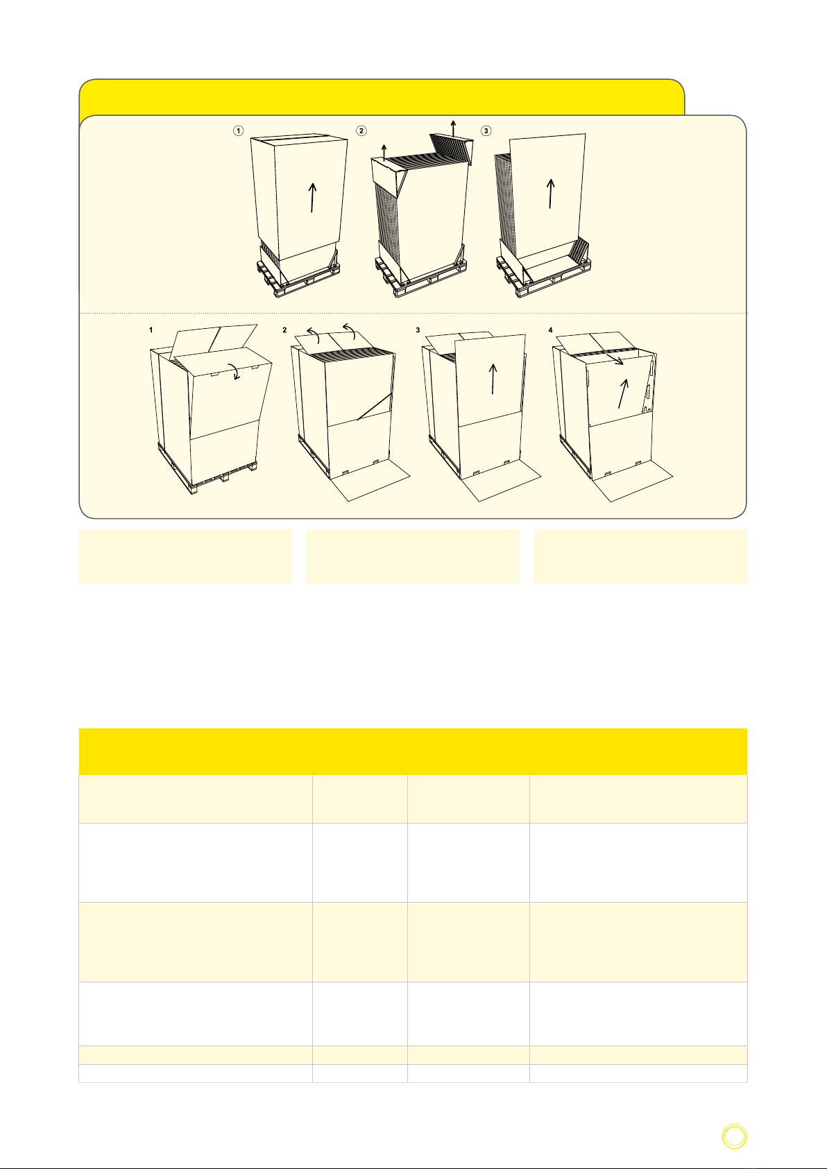
ACHTUNG: Bitte achten Sie unbedingt
auf die Entnahmehinweise auf der Ver-
packung! Lösen Sie auf keinen Fall das
hintere Halteband!
ACHTUNG: Beim Umgang mit den Mo-
dulen!
• Tragen Sie die Module mit beiden Hän-
den. Benutzen Sie die Anschlussdose
oder das Kabel nicht als Griff und ziehen
Sie auch bei der Montage nicht am An-
schlusskabel. Siehe Abb. 1.
• Setzen Sie die Module keinen harten
Erschütterungen aus! Stellen Sie die Mo-
dule nicht unsanft auf hartem Boden ab.
Stellen Sie die Module nicht auf deren
Ecken ab. Legen Sie die Module nicht un-
geschützt aufeinander. Legen Sie keine
Gegenstände auf den Modulen ab. Be-
treten Sie die Module nicht. Lassen Sie
die Module nicht fallen und bearbeiten
Sie sie nicht mit harten und spitzen Ge-
genständen.
• Das Verbinden der Module hat mit Sorg-
falt und ohne Gewalteinwirkung zu er-
folgen. Halten Sie alle elektrischen Kon-
takte sauber und trocken.
• Für die eventuelle Zwischenlagerung
sollte ein trockener, belüfteter Raum zur
Verfügung gestellt werden.
• Zur Anlagendokumentation empfiehlt
es sich, im Anlagenplan die Seriennum-
mer am Einbauort zu notieren.
3. Delivery and handling
of the modules
The goods must be immediately examined
after delivery for their completeness and
that they are not damaged. Any damages
must be recorded on the driver’s freight
document and the company Heckert Solar
must be immediately informed of this in
writing. Our Brand product modules are ge-
nerally packed on a disposable one-way pa-
lette in a standing position, so that they can
be carefully removed individually by a sing-
le person. Handling of the modules require
extreme care and attention. Especially lami-
nates without any module frame are extre-
mely sensitive to shock. Therefore take great
care when unpacking, transporting and for
intermediate storage. Leave the modules in
their packaging until they are to be installed.
Do not stack the palettes.
ATTENTION: Please take note of the me-
thod of removal on the packaging! Ne-
ver under any circumstances remove the
rear-retaining band!
ATTENTION: When handling the modu-
les!
• Always carry the modules with both
hands. Do not utilize the connection box
or the cable as a handle and never pull
on the connecting cable when assemb-
ling. See figure 1.
• Do not cause any heavy vibrations to
the modules! Do not place the modu-
les roughly onto hard bases. Do not put
the modules down onto their corners.
Do not place the modules one on top of
the other without any protection. Never
lay any items onto the modules. Do not
walk on or stand on the modules. Never
drop the modules and never work on
them with hard or pointed objects.
• Connecting the modules up must be car-
ried out carefully and without any force
required. Keep all electrical contacts
clean and dry.
• If intermediate storage is required then
a dry well ventilated room should be
made available.
• It is recommended to record the series
number in the appliance documentation
appliance plan at the assembly location.
3. Livraison & traitement
des modules
A la livraison, contrôler immédiatement si
la marchandise est complète et intacte. Les
dommages sont à noter sur la lettre de vo-
iture du chauffeur et Heckert Solar à infor-
mer immédiatement par écrit. En général,
nos modules sont emballés debout sur une
palette non retour si bien qu’ils peuvent être
déballés individuellement par une person-
ne en ménageant le dos. La manipulation
des modules exige le plus grand soin. Les
stratifiés sans cadre de module sont parti-
culièrement sensibles aux chocs. Prudence
donc lors du déballage, du transport et de
l’entreposage. Laissez les modules dans leur
emballage jusqu’à leur utilisation. Ne pas
empiler les palettes.
ATTENTION: Observez impérative-
ment les consignes d’enlèvement sur
l’emballage! Ne détachez en aucun cas le
ruban de maintien!
ATTENTION: Dans la manipulation des
modules!
• Portez les modules à deux mains.
N’utilisez pas la boîte de jonction ou le
câble comme poignée et ne tirez pas sur
le câble de raccordement lors du monta-
ge. Voir figure 1.
• N’exposez pas les modules à de fortes
secousses! Ne posez pas les modules
brusquement sur un sol dur. Ne posez
pas les modules sur leurs angles. Ne po-
sez pas les modules l’un sur l’autre sans
protection. Ne déposez pas d’objets sur
les modules. Ne marchez pas sur les mo-
dules. Ne laissez pas tomber les modules
et ne les traitez pas avec des objets durs
et pointus.
• Le raccordement des modules doit être
effectué avec soin et sans usage de la
force. Maintenez tous les contacts élec-
triques propres et secs.
• Une salle sèche et aérée doit être dispo-
nible pour un éventuel entreposage.
• Pour documenter l’installation, il est re-
commandé de noter le numéro de série
dans le plan de l’installation sur le lieu
de montage.
August 2011 8Heckert Solar AG | Carl-von-Bach-Str. 11 | 09116 Chemnitz
Abb. 1 | Fig. 1: Neue Modulverpackungen 2011 | New packaging 2011 | Nouveaux emballages en 2011
4. Hinweise zum Modul
Zertifizierungen
Die Heckert Solar AG legt als eines der wenig
verbliebenden Unternehmen, die ihre Mar-
kenmodule zu 100% in Deutschland produ-
ziert, großen Wert auf Zertifizierungen der
Produktqualität:
4. Notifications concerning the
module
Certification
The company Heckert Solar AG is one of the
few remaining companies who manufacture
their Brand product modules to 100% in Ger-
many and sets great value on the certifica-
tion of their product quality:
4. Consignes sur le module
Certifications
En tant que l’une des dernières entreprises
produisant ses modules de marque à 100%
en Allemagne, Heckert Solar AG accorde une
grande importance aux certifications de
qualité du produit:
Prüfung
Examination
Essai
Institut
Institute
Institut
Zertifikatsnummer
Certificate number
Numéro de certificat
Link
Link
Lien
Ammoniakbeständigkeit
Ammoniac contents
Résistance à l’ammoniac
DLG 6002F www.dlg-test.de/pbdocs/6002F.pdf
Bauarteignung und Bauartprüfung nach IEC61215
Component suitability and component examination
according to IEC61215
Essai de corrosion au brouillard salin suivant IEC
61215
TÜV-Rheinland
Technical Control
Board Rhineland
TÜV-Rheinland
PV 60028020
PV 60029904
PV 60037299
PV 60037300
www.tuvdotcom.com/certificates/60028020
www.tuvdotcom.com/certificates/60029904
www.tuvdotcom.com/certificates/60037299
www.tuvdotcom.com/certificates/60037300
Sallznebelkorossionsprüfung nach IEC 61701
Salt mist corrsion test according to IEC 61701
Essai de corrosion au brouillard salin suivant IEC
61701
TÜV-Rheinland
Technical Control
Board Rhineland
TÜV-Rheinland
PV 60029897
PV 60029898
PV 60038971
PV 60038973
www.tuvdotcom.com/certificates/60029897
www.tuvdotcom.com/certificates/60029898
www.tuvdotcom.com/certificates/ 60038971
www.tuvdotcom.com/certificates/ 60038973
Sicherheitsprüfung nach IEC 61730
Safety examination according to IEC 61730
Essai de sécurité suivant IEC 61730
TÜV-Rheinland
Technical Control
Board Rhineland
TÜV-Rheinland
PV 60033199
PV 60039076
www.tuvdotcom.com/certificates/60033199
www.tuvdotcom.com/certificates/60039076
Microgeneration Certification Scheme (MCS) BBA MCS BBA0058 www.bbacerts.co.uk/PDF/MCSBBA0058i1.pdf
pdfpass‘innovation no 10-116 for Solrif® CSTB 2011 - 154
für HS P SOLRIF® Module/for HS P SOLRIF® modules/pour des modules HS P SOLRIF®
für 26 NeMo® P Module/ for 26 NeMo® P modules / pour 26 modules NeMo® P

August 2011 9Heckert Solar AG | Carl-von-Bach-Str. 11 | 09116 Chemnitz
Einsatz
Bitte beachten Sie für den Einsatz unse-
rer Markenmodule insbesondere folgende
Punkte:
• Das Solarmodul nicht in Flüssigkeit ein-
tauchen.
• Das Solarmodul ist nicht seewasser-
tauglich (empfohlener Abstand zum
Meer 500 m).
• Das Modul darf nicht außergewöhn-
lichen chemischen Belastungen (z.B.
Emissionen durch produzierende Betrie-
be) ausgesetzt werden.
• Keine Linsen oder Spiegel zur Lichtbün-
delung verwenden (Gefahr durch Über-
hitzung).
• Vermeiden Sie die Beschädigung des
Moduls durch Hartmetall- oder Dia-
mantgegenstände.
• Solarmodule vor Überspannung schüt-
zen z.B. Spannungsspitzen von Batterie-
Ladegeräten, Generatoren der Lichtma-
schinen usw., im Zweifelsfall bitte bei
Ihrem Fachhändler nachfragen.
• Sollen Solarmodule an Speicherbatte-
rien angeschlossen werden, sind die
Sicherheitshinweise des Batterieherstel-
lers zu beachten.
• Kinder von Solarmodulen fernhalten.
In südlichen Regionen kann ein PV-Modul
höhere Ströme und Spannungen liefern als
es bei den genormten Prüfbedingungen
(Standard Testbedingungen) angegeben
wurde. Zur Bestimmung der Spannungs-
bemessungswerte von Bauteilen, Strom-
bemessungswerte von Leitern, Größen der
Sicherungen die an den Ausgang von PV-
Modulen angeschlossen werden, sollten
deshalb die auf dem Modul angegebenen
Werte von Isc und Uos mit einem Faktor von
1,25 multipliziert werden.
Der höchste Bemessungswert für den Über-
stromschutz (Rückstromfestigkeit) beträgt
15A.
Utilization
Please especially note the following points
for our brand product modules:
• The solar module must not be immersed
in liquids.
• The solar module is not suitable for sea-
water (recommended distance to sea
500 m).
• The module may not be exposed to
extraordinary chemical loading (for ex-
ample – emissions from manufacturing
companies).
• Do not utilize lenses or mirrors for light
bundling (danger of over-heating).
• Avoid damaging the module by hard me-
tal or diamond materials .
• Protect the solar modules from excess
voltages for example, voltage peaks
from battery charging devices, gene-
rators from dynamo’s etc., in case of
uncertainty please make enquiries with
your specialist dealer.
• If solar modules are to connected to sto-
rage batteries then take note of the ma-
nufacturers safety instructions.
• Keep children well away from solar mo-
dules.
In southern regions a PV module can deli-
ver higher current and voltages than stated
under the standardized testing condition.
Therefore the determination of the voltage
calculated values of components, current
calculated values for conductors, size of the
safety fuses to be fitted to the output of
the PV modules stated values of Isc and Uos
should be multiplied by a factor of 1.25.
The highest calculated value for the overcur-
rent protection (reverse current stability) is
15A.
Utilisation
Veuillez observer les points suivants pour
l’utilisation de nos modules de marque:
• Ne pas plonger le module solaire dans
un liquide.
• Le module solaire n’est pas résistant à
l’eau de mer (distance recommandée de
la mer 500 m).
• Le module ne doit pas être exposé à des
charges chimiques exceptionnelles (ex:
émissions d’entreprises de production).
• Ne pas utiliser de lentilles ou de miroirs
pour concentrer la lumière (danger de
surchauffe).
• Eviter d’endommager le module par des
objets en métal dur ou en diamant.
• Protéger les modules solaires de la sur-
tension, par exemple des pointes de
tension de chargeurs de batterie, des
générateurs de dynamos etc. ; en cas de
doute, adressez-vous à votre commer-
çant spécialisé.
• Observer les consignes de sécurité du
fabricant de batterie si les modules so-
laires doivent être raccordés à des batte-
ries accumulatrices.
• Tenir les enfants éloignés des modules
solaires.
Dans les régions méridionales, un module PV
peut livrer des courants et des tensions plus
élevés qu’indiqué dans les conditions d’essai
normalisées (conditions d’essai standards).
Pour déterminer les valeurs de dimension-
nement de tension des éléments de const-
ruction, les valeurs de dimensionnement de
courant des conducteurs, les dimensions des
fusibles raccordés à la sortie des modules PV,
il convient de multiplier les valeurs de Isc et
Uos indiquées sur le module par un facteur
de 1,25.
La valeur de dimensionnement la plus élevée
de protection de surintensité de courant (ré-
sistance au courant de retour) est de 15 A.
August 2011 10Heckert Solar AG | Carl-von-Bach-Str. 11 | 09116 Chemnitz
5. Modulmontage
Markenmodule von Heckert Solar gibt es in
den Ausführungen mit Standardrahmen aus
Aluminium oder als Laminat ohne Rahmen
für die Aufdach- und Indachmontage sowie
mit dem Solrif®-Rahmen für die Indach-
montage im Solrif®-System. Mit unserem
eigenen Montagesystem und den Systemen
unserer Partnern Schweizer (Solrif®-Indach),
Schletter können wir für fast jede Dachan-
lage sowie für einige Fassadenanlagen eine
Lösung anbieten. Sollten dennoch andere
Systeme verwendet werden, sind unbedingt
die Hinweise des betreffenden Anbieters zu
beachten.
Eine Anleitung kann auf der jeweiligen
Homepage abgerufen werden:
• www.heckertsolar.com
• www.schweizer-metallbau.ch
• www.schletter.de
Allgemeine Hinweise zur Aufdachmontage
Alle Standardrahmen- und Laminat-Module
sind aufgrund ihrer hohen Stabilität sowohl
für eine Hoch- als auch für eine Quermonta-
ge geeignet. Die Module sind dabei immer
an der langen Seite zu klemmen, es ist auf
die Klemmbereiche zu achten (Vgl. Abb. 2).
Bitte beachten Sie, dass deshalb je nach Ein-
baulage und Dachart (Sparren oder Pfetten)
ein Kreuzschienensystem notwendig wer-
den kann.
Wir empfehlen Laminate zur Lastverteilung
vollständig am Rand zu unterstützen.
Abrutschsicherung
Um ein Abrutschen der Module bei der
Montage auf einer geneigten Ebene zu ver-
meiden und die Montage zu erleichtern,
sind unsere Modulrahmen mit Bohrungen
für Abrutschsicherung versehen. Siehe Abb.
2 Detail X. In diesen Löchern im Modulrah-
men werden Zylinderkopfschrauben mit
Innensechskant angebracht. Die Sicherung
der Schrauben erfolgt mit Unterlegscheibe
und Mutter oder mittels selbstsichernder
Mutter. Für die Abrutschsicherung wird eine
Schraube M 5 x10 VA und zugehöriger Zahn-
scheibe und Mutter empfohlen.
5. Module installation
Brand product modules from the compa-
ny Heckert Solar are available in the design
with a standard frame made from Alumini-
um or as laminate without a frame for on-
roof or in-roof installation as well as with
the Solrif®-frames for in-roof installation in
the Solrif®-system. With our own installati-
on system and the systems from our partner
company Schweizer (Solrif®-Indach), Schlet-
ter we can find and offer a solution for near-
ly every roof appliance as well as for several
facade appliances. If however other systems
are to be utilized then it is absolutely neces-
sary to note the instructions given by the re-
spective supplier.
Instructions can be requested from the res-
pective home pages:
• www.heckert-solar.com
• www.schweizer-metallbau.ch
• www.schletter.de
General instructions for on-roof installa-
tion
All standard frames and laminate modules
are due to their high stability suitable for
high as well as transverse installation. The
modules must always be clamped on the
longer side, please take notice of the clam-
ping instructions (see fig. 2). Please also note
that it could be necessary to utilize a cross-
bar system according to the installation
position and type of roof (rafter or binding
rafters (purlins)).
We recommend that laminate is completely
supported at the edges for correct load dis-
tribution.
Securing against slipping
To simplify installation and to avoid the
slipping of the modules when installing on
a angled roof, our module frames are fitted
with bore holes for securing against slipping.
Refer to fig. 2 Detail X. Fitted into these holes
in the module frames are cylinder head bolts
with an internal hexagon. Securing of the
bolts is implemented with spacers and a nut
or by means of a self-securing nut. It is re-
commended that a bolt M 5x10 VA with the
appropriate toothed spacer is utilized for se-
curing against slipping.
5. Montage du module
Les modules de marque Heckert Solar sont
disponibles dans les modèles à cadre stan-
dard en aluminium ou stratifié sans cadre
pour montage sur toiture ou dans toiture
ou avec cadre Solrif® pour montage dans to-
iture dans le système Solrif®. Grâce à notre
propre système de montage et aux systèmes
de nos partenaires Schweizer (dans toiture
Solrif®), Schletter, nous sommes en mesure
d’offrir des solutions pour presque toutes les
installations de toiture et quelques installa-
tions de façade. Si d’autres systèmes doivent
être utilisés, observer impérativement les
consignes de l’offreur concerné.
Un mode d’emploi peut être consulté sur les
différents sites suivants:
• www.heckertsolar.com
• www.schweizer-metallbau.ch
• www.schletter.de
Consignes générales pour montage sur
toiture
Tous les modules à cadre standard et stratifi-
és conviennent tant au montage vertical que
transversal en raison de leur grande stabili-
té. A cet effet, les modules doivent toujours
être serrés sur le côté long et il faut veiller
aux zones de serrage (voir fig. 2). Notez
qu’un système crossbar peut être nécessaire
selon la situation de montage et le type de
toit (chevrons ou pannes).
Nous vous recommandons de soutenir les
stratifiés entièrement en bordure pour la
répartition de la charge.
Sécurité anti-glissement
Pour éviter le glissement des modules sur
un plan incliné lors du montage et faciliter
ce dernier, les cadres de nos modules sont
pourvus d’alésages pour une sécurité anti-
glissement. Voir Fig. 2 Détail X. Des vis à tête
cylindrique à six pans intérieur sont placées
dans ces trous du cadre du module. La fixati-
on des vis s’effectue avec une rondelle et un
écrou ou un écrou autodesserrable. Pour la
sécurité anti-glissement, nous vous recom-
mandons une vis M 5 x10 VA avec la rondelle
dentée et l’écrou allant de pair.

August 2011 11Heckert Solar AG | Carl-von-Bach-Str. 11 | 09116 Chemnitz
Belastung der Module
Achten Sie auf die Einhaltung der mecha-
nischen Maximalbelastung, insbesondere
auch unter Berücksichtigung der standor-
tabhängigen Belastungen durch z.B. Wind
und Schnee (DIN 1055-4/5). Beachten Sie,
dass sich das Modul bei hohen Belastun-
gen durchbiegen kann. Verwenden Sie kein
Material, welches das Modul z.B. aufgrund
von spitzen, scharfkantigen oder unebenen
Strukturen beschädigt werden kann. Die an-
zusetzende Schneelast auf dem Boden sk in
kN/m² ergibt sich aus der jeweiligen Schnee-
lastzone, dem Gebäudestandort und der
Geländehöhe über NN. Die anzusetzende
Windlast ist für den Projektstandort aus der
Windzonenkarte zu bestimmen, die neben
Windzonen auch die Standortsituation be-
rücksichtigt. Bei Gebäuden bis zu einer Höhe
von 25m kann die anzusetzende Windlast
nach einem vereinfachten Verfahren ermit-
telt werden. Abhängig von Gebäudehöhen
wird die Windlast als Geschwindigkeits-
druck q in kN/m³ angegeben. Windlast- und
Schneezonenkarten erhalten Sie z.B. im In-
ternet über
• http://de.wikipedia.org/wiki/Schnee-
last;
• http://de.wikipedia.org/wiki/Windlast.
ACHTUNG: Bitte beachten Sie, dass die
alleinige Verantwortung für Planung
und Ausführung des Projektes beim aus-
führenden Fachbetrieb liegt und es in ei-
nigen Fällen notwendig ist, eine Objekt-
statik zu erstellen!
Loading the Modules
Make sure that the maximum mechanical
load is not exceeded, in particular while also
taking the site-dependent loads (e.g. wind
and snow (in accordance with German stan-
dard DIN 1055-4/5)) into account. Please
note that the module can bend under heavy
loads. Do not use materials which can dama-
ge the module, e.g. due to pointed, sharp-
edged or uneven structures. The snow load
sk in kN/ m2 to be applied on the ground
results from the respective snow load zone,
the building site and the elevation above sea
level of the property. The wind load to be ap-
plied must be determined for the project site
from the wind zone map which, in addition
to wind zones, also takes the situation at the
site into account. For buildings up to a height
of 25 m, the wind load to be applied can be
determined using a simplified method. The
wind load is specified as the velocity pres-
sure q in kN/m2 depending on the building
height.
Wind loading and snow zone maps can be
obtained for example over the internet un-
der the following link:
• http://de.wikipedia.org/wiki/Schnee-
last;
• http://de.wikipedia.org/wiki/Windlast.
ATTENTION: Please ensure that the ge-
neral responsibility for planning and
implementation of the project is exclusi-
vely that of the implementing specialist
company and in several cases is will be
necessary to create an object structural
analysis!
Charge des modules
Nous vous prions de bien vouloir observer la
charge mécanique maximale, notamment
en tenant compte des charges spécifiques
du site, telles que celles dues au vent et à
la neige (DIN 1055-4/5). Prière d’observer
que le modulepeut s’infléchir sous char-
ges élevées. Ne pas utiliser du matériel qui
risque d’endommager le module, à cause
d’une structure pointue, anguleuse ou
rugueuse, par exemple. La charge de neige
à prévoir au sol, sk, en kN/m2, estbasée sur
la zone de charge de neige respective, sur
l’implantation du bâtiment, et sur l’altitude
au-dessus de la mer. La surcharge de vent à
prévoir pour le site du projet sera détermi-
née sur la base de la carte des zones de vent
qui tient compte non seulement des zones
de vent mais aussi de la situation du site.
Pour les bâtiments ayant une hauteur allant
jusqu’à 25 m, la surcharge de vent à prévoir
peut être déterminée d’après une méthode
simplifiée. Lacharge de vent est indiquée
comme pression de vitesse q en kN/m2, en
fonction de la hauteur du bâtiment.
Vous recevez des cartes sur les zones de
charge du vent et de neige sur Internet, par
exemple à:
• http://de.wikipedia.org/wiki/Schnee-
last;
• http://de.wikipedia.org/wiki/Windlast.
ATTENTION: Observez que la seule re-
sponsabilité de la conception et de
l’exécution du projet est du ressort de
l’entreprise spécialisée effectuant le tra-
vail et qu’il est nécessaire d’établir une
statique de l’objet dans certains cas!
Abb. 2 | Fig. 2 : Modulmaße und Klemmbereiche NeMo® P | Dimensions and clamping area of NeMo® P |
Dimensions et zones de cerrage du NeMo® P
Detail X

August 2011 12Heckert Solar AG | Carl-von-Bach-Str. 11 | 09116 Chemnitz
En cas de plusieurs strings, nous vous re-
commandons de trier les modules suivant
l’intensité du courant (IMPP). Cela per-
met de garantir le rendement maximal de
l’installation, car le module le plus faible dé-
termine la puissance du string complet.
ATTENTION: Ne pas monter les modules
endommagés!
Pose des lignes
Pour chaque string, on a besoin de 2 câb-
les. Nous vous recommandons d’utiliser
des cables solaires spéciaux correspondant
à la norme CEI 60228, Classe 5. Le diamètre
minimal est de 4 mm2. Les câbles + et – ne
doivent pas être confondus. Assurez-vous
que vous éviter que les connecteurs à fiches
reposent durablement dans l’eau.
6. Verbinden und Anschluss der
Module
6. Connecting and coupling of the
modules
6. Raccordement et branchement
des modules
Die Module werden mittels des Kabels mit
Wieland/Prysmian-Steckverbindern direkt
an der Anschlussdose zu einem String ver-
bunden. Durch die Verwendung nur eines
Kabels wird vermieden, dass die Steckver-
binder dauerhaft im Wasser liegen.
• Bitte beim Anstecken nicht am An-
schlusskabel ziehen.
• Bei Auslieferung ist das Kabel an der lin-
ken Seite der Dose (auf der Dose mit +
gekennzeichnet) angesteckt.
• Am nächsten Modul wird die Buchse
rechts (auf der Dose - ) angesteckt.
• Das heißt es wird immer Dose + mit Ka-
bel - verbunden.
• Die Form der Stecker bzw. Buchse ist so
gestaltet dass es keine Verwechslungen
geben kann. Eine ordnungsgemäße Ver-
bindung ist hergestellt, wenn die Steck-
verbinder eingerastet sind (leichtes Kli-
cken).
• Die Steckverbinder haben die Schutz-
klasse IP68, die Anschlussdose IP65. Bei-
de Komponenten sind damit dauerhaft
gegen Staubeinflüsse geschützt.
• Zum Lösen der Verriegelung der Steck-
verbinder ist unbedingt geeignetes
Werkzeug zu verwenden.
ACHTUNG: Öffnen Sie nicht die An-
schlussdose, ziehen Sie nicht am An-
schlusskabel (Vgl. Abb. 3) und achten
Sie auf eine ordnungsgemäße Steckver-
bindung! Die Schutzklasse ist sonst nicht
mehr gewährleistet!
Wir empfehlen bei mehreren Strings das
Sortieren der Module nach der Stromstärke
(IMPP). Dadurch kann der maximale Ertrag
der Anlage gewährleistet werden, denn das
schwächste Modul bestimmt die Leistung
des gesamten Strings.
ACHTUNG: Es dürfen keine Module mit
Beschädigungen montiert werden!
Leitungsverlegung
Je String werden 2 Kabel benötigt, die den
Solargenerator mit dem Wechselrichter
verbinden. Hier empfehlen wir spezielles
Solarkabel zu verwenden, das der Norm IEC
The modules are connected by means of
the cable with a Wieland/Prysmian plug
connector directly on the connecting box as
a string. It is avoided that the plug connec-
tions are continuously in water by utilization
of a connection cable.
• When connecting please do not tug on
the connecting cables.
• The cable is plugged onto the left side
of the box upon delivery (labelled with
+ on the box).
• On the next module the socket is
plugged onto the right hand side (on the
box -).
• That means the box + will always be
connected up to a cable.
• The form of the plug or socket is desi-
gned so that there can be no mistakes
made. A correct connection is made
when the plug connectors have clicked
into place (light clicking).
• The plug connectors are protection class
IP68, the connection box IP65. Both
components are therefore permanently
protected against and dust influences.
ATTENTION: Do not open the connection
boxes, do not pull on the connection
cables (see fig. 3) and take note that a
correct plug connection is implemented!
Otherwise the protection class is not gu-
aranteed!
Les modules sont directement raccordés au
moyen du câble par des connecteurs à fiches
Wieland/Prysmian à la boîte de jonction en
un string. L’utilisation d’un seul câble permet
d’éviter que les connecteurs à fiches repo-
sent durablement dans l’eau.
• Ne pas tirer sur le câble de raccordement
lors du branchement.
• A la livraison, le câble est fiché côté gau-
che de la boîte (marqué d‘un + sur la
boîte).
• La douille est fichée à droite (- sur la boî-
te) sur le module suivant.
• La jonction est toujours boîte + / câble -.
• La forme du connecteur, respectivement
de la boîte, est conçue de telle manière
qu’aucune confusion ne soit possible.
Un raccordement conforme est établi
quand les connecteurs à fiches ont pris
encoche (léger clic).
• Les connecteurs à fiches ont la classe
de protection IP68, la boîte de jonction
IP65. Les deux composants sont donc
protégés durablement des influences de
la poussière.
ATTENTION: N’ouvrez pas la boîte de
jonction, ne tirez pas sur le câble de rac-
cordement (voir fig. 3) et veillez à établir
une connexion conforme! Sinon, la classe
de protection n’est plus garantie!
If there are several strings we recommend
the sorting of the modules according to
Abb. 3 / Fig. 3
August 2011 13Heckert Solar AG | Carl-von-Bach-Str. 11 | 09116 Chemnitz
60228 Klasse 5 entspricht. Der Mindest-
durchmesser beträgt 4 mm². Um Verluste zu
minimieren sollte bei größeren Entfernun-
gen der Kabelquerschnitt entsprechend ver-
größert werden. Beim Anschluss der Strings
an den Wechselrichter ist auf die Polarität
zu achten. Diese + und – Kabel dürfen nicht
vertauscht werden. Bitte achten Sie darauf,
dass die Steckverbinder nicht dauerhaft im
Wasser liegen.
ACHTUNG: Bitte achten Sie auf eine kor-
rekte Verbindung der Stecker und Buch-
sen!
Die Strings (+ und - Kabel) werden zum
Wechselrichter geführt und an die DC-Solar-
Eingänge angeschlossen. Die Modulstecker
sind gekennzeichnet. Das Kabel am + Stecker
des Moduls ist am Wechselrichter auf den +
Eingang anzuschließen. Bei – ist analog zu
verfahren. Um Leiterschleifen zu vermeiden
sollten die Strings (+ und -) gemeinsam ver-
legt werden. Die Dachdurchdringung sollte
sich möglichst an einem Punkt befinden.
Die Manipulation des Modulkabels und /
oder des Steckers bewirkt den Ausschluß
von der Produkt- und Leistungsgewährleis-
tung.
Für den Anschluss der Solarkabel an die Mo-
dule bzw. Wechselrichter sind nur zertifizier-
te, passende Steckverbindungen zugelassen.
Die Steckverbinder werden mit Spezialzan-
gen auf das Solarkabel aufgecrimpt. Mit ei-
nem Multimeter/Voltmeter sollten die ein-
zelnen Strings auf Polarität und Spannung
vor dem Anschluss an den Wechselrichter
überprüft werden.
Die Installation bzw. der Anschluss des/der
Wechselrichter ist nach Herstellervorschrift
auszuführen.
the current strength (IMPP). In that way the
maximum output is guaranteed from the
installation, because the weakest module
determines the power delivered from the
complete string.
ATTENTION: Damaged modules must not
be installed!
Laying the cables
Two cables are required per string. It is re-
commended to use special solar cable corre-
sponding to the standard IEC 60228 class 5.
The minimal diameter is 4 mm2. It is impor-
tant not to reverse the + and – cables. Please
pay attention to the connectors not laying in
the water permanently.
ATTENTION: Please note the correct con-
nection between the plug and the so-
ckets!
The strings (+ and – cables) are fed into the
inverter and connected to the DC solar in-
puts. The module sockets are marked. The
cable on the + socket of the module should
be connected to the inverter at the + input.
The sameprocedure applies to the – socket
and – input. To avoid conductor loops the
strings (+ and –) should be laid together. The
cable groove on the cross profile can hereby
be used. If possible roof penetration should
only be at one point.
The manipulation of the module cable and/
or the plug causes the exclusion of the
product and performance warranty
Only certified socket connectors are autho-
rized for connecting the solar cables to the
modules or inverters, resp. The socket con-
nectors are crimped on with special forceps.
The individual strings can be checked for
polarity and voltage with a multi-meter/
voltmeter.
The connection of the inverters should be
done in accordance with the manufacturer’s
instructions.
ATTENTION: Veillez à la connexion cor-
recte des connecteurs et des douilles!
Les strings (câbles + et –) sont guidés vers
l’onduleur et raccordés aux entrées solaires
à courant continu. Les connecteurs de mo-
dules sont marqués. Le câble au connecteur
+ du module doit être connecté à l’entrée +
de l’onduleur. Procéder de manière analogue
pour –. Pour éviter les boucles de lignes, il est
recommandé de poser les strings (+ et –) en
commun. Ce faisant, on peut faire usage du
caniveau de câble se trouvant sur le profilé
transversal. Si possible, la pénétration de toi-
ture doit être concentrée sur un seul endroit.
La manipulation des câbles des modules
et / ou de la fiche a pour conséquence
l‘exclusion de la garantie du produit et de
prestation.
Pour raccorder les câbles solaires aux modu-
les et/ou onduleurs, il faut utiliser unique-
ment des connecteurs certifiés conformes.
Les connecteurs sont sertis avec des pinces
spéciales. La polarité et la tension des diffé-
rents strings peuvent être vérifiées à l’aide
d’un multimètre / voltmètre.
Le raccordement des onduleurs s’effectuera
selon les instructions du constructeur.

August 2011 14Heckert Solar AG | Carl-von-Bach-Str. 11 | 09116 Chemnitz
ACHTUNG: Je nach Modulleistung und
Wechselrichtertyp sind verschiedene
Stringlängen möglich!
Parallelverschaltung von PV-Modulen
Bei der Verschaltung unserer Markenmodu-
le ist zu beachten, dass bei der Parallelver-
schaltung von mehr als 2 Strings Stringsiche-
rungen (15A) eingesetzt werden müssen.
Der maximale Stromwiderstand beträgt
15A. Werden mehr als zwei Strings parallel
verschaltet, kann dieser im Fehlerfall über-
schritten werden.
Elektrische Installation
Der Anschluss des Wechselrichters an das
öffentliche Stromnetz muss unbedingt von
einem zugelassenen Fachbetrieb ausgeführt
werden.
ACHTUNG: Auch bei geringer Einstrah-
lung entsteht bereits hohe Gleichspan-
nung. Niemals blanke + und - Leitungen
im Betrieb berühren!
Erdung
Die Erfordernisse des Blitz- und Überspan-
nungsschutzes sind von örtlichen Gegeben-
heiten abhängig. Eine fachgerechte Erdung
der Modulrahmen liegt in der Verantwor-
tung des installierenden Unternehmens
und ist am Modulrahmen an der dafür ge-
kennzeichneten Position anzubringen (Vgl.
Abb. 4). Für die Erdung ist eine Schraube M4
vorgeschrieben. Die Befestigung muss mit
Federring oder Zahnscheibe erfolgen, damit
sicher gestellt ist, dass das Eloxal durchdrun-
gen wird.
Ist auf dem Gebäude bereits ein äußeres
Blitzschutzsystem vorhanden oder vorgese-
hen, muss die PV-Anlage in das Schutzkon-
zept gegen direkten Blitzeinschlag integriert
werden. Bei Einsatz von trafolosen Wechsel-
richtern muss wegen der fehlenden galva-
nischen Trennung aus Personenschutzgrün-
den eine Erdung erfolgen. Landesspezifische
Normen sind dabei einzuhalten.
NeMo®P
Max. Systemspannung 1000 VDC
Max. system voltage 1000 VDC
Tension système maxi 1000 VDC
NeMo®M
Max. Systemspannung 1000 VDC
Max. system voltage 1000 VDC
Tension système maxi 1000 VDC
Typ
Type
Type
Anzahl
Numbers
Nombre
Typ
Type
Type
Anzahl
Numbers
Nombre
NeMo®P 210 - 220 25 NeMo®M 210 - 215 25
NeMo®P 195 - 205 26 NeMo®M 205 26
ATTENTION: Different string lengths are
possible according to the module pow-
er output and the d.c. to a.c. converter
type!
Parallel interconnecting of PV modules
When interconnecting our PV modules,
please note that parallel interconnecting of
more than 2 strings requires the installation
of string fuses (15 amps). The maximum fuse
current was stated to be 15 amps; if more
than two strings are interconnected in pa-
rallel, this value might be exceeded in the
event of a fault.
Electrical installation
It is absolutely imperative that the inverter
be connected to the public power supply
network by a certified specialist.
!ATTENTION: Even with a low amount of
radiation a high direct current is created.
Never touch bare + wires and – cables
when in operation!
ATTENTION: Différentes longueurs de
string sont possibles suivant la puissance
du module et le type d’onduleur!
Câblage parallèle des modules PV
Lors du câblage de nos modules PV, noter
que des fusibles de ligne (15A) doivent être
utilisés pour le câblage parallèle de plus de 2
lignes. Le fusible de courant maxi indiqué est
de 15A; il peut être dépassé en cas d‘erreur si
deux lignes sont câblées en parallèle.
Installation électrique
Le raccordement de l’onduleur au réseau pu-
blic doit impérativement être réalisé par une
entreprise spécialisée et autorisée.
ATTENTION: Une tension continue élevée
est aussi générée avec une faible radia-
tion. Ne jamais toucher les lignes dénu-
dées + et - !
Abb. 4 | Fig. 4: Anschluss Erdungsanschluss | Connection for earthing |
Correspondance de mise à la terre
Earthing
The requirements for lightning and overloa-
ding protection depend upon the local cir-
cumstances. Correct earthing of the module
frame is the responsibility of the company
implementing the installation and must be
fitted onto the module frame on the positi-
on labelled for this (see fig. 4). A screw M4
is prescribed for this. The fixing must be im-
plemented with a spring washer or toothed
Terre
Les conditions de la protection contre la
foudre et la surtension sont fonction des
données locales. La mise à la terre conforme
des cadres de module est de la responsabi-
lité de l’entreprise d‘installation et doit être
effectuée sur le cadre du module à la positi-
on marquée à cet effet (voir fig. 4). Une vis
M4 est prescrite pour la terre. La fixation
doit se faire par rondelle-ressort ou rondel-
August 2011 15Heckert Solar AG | Carl-von-Bach-Str. 11 | 09116 Chemnitz
Brandschutz
Die Errichtungen von Aufdachanlagen kön-
nen die Brandsicherheit eines Gebäudes
beeinflussen; unsachgemäße Installationen
können zu einer Gefährdung im Brandfall
führen. Im Falle von Aufdachanwendungen
müssen die Heckert Solar Markenmodule
oberhalb eines feuerbeständigen Unter-
grundes angebracht werden. Das Modul ist
ein „nicht explosionsgeschützes Betriebs-
mittel“. Daher darf es nicht in der Nähe von
leicht entzündlichen Gasen und Dämpfen
(z.B.: Tankstellen, Gasbehälter, Farbspritz-
anlagen) installiert werden. Das Modul darf
nicht neben offenem Flammen und ent-
flammbaren Materialien installiert werden.
Spezielle Brandbekämpfungsvorschriften
für Häuser mit stromproduzierenden Photo-
voltaikanlagen liegen den Feuerwehren vor.
Arbeit auf dem Dach
Beachten Sie die gültigen Unfallverhütungs-
vorschriften. Führen Sie die Installationsar-
beiten nicht bei starkem Wind aus. Sichern
Sie sich und andere Personen vor dem Her-
abstürzen. Verhindern Sie das mögliche Her-
abfallen von Gegenständen. Sichern Sie den
Arbeitsbereich, damit keine anderen Perso-
nen verletzt werden können.
le dentée pour garantir que l’Eloxal est bien
transpercé.
Si un système extérieur de protection cont-
re la foudre est déjà présent ou prévu sur le
bâtiment, une installation PV doit être inté-
grée au concept de protection contre la chu-
te directe de la foudre. En cas d’utilisation
d’onduleurs sans transfo, une mise à la terre
doit être effectuée pour des motifs de pro-
tection des personnes en raison de la sépa-
ration galvanique manquante. A cet effet,
observer les normes spécifiques au pays.
washer so that it is ensured that the Eloxal is
completely penetrated.
If there is an existing lightning protection
system available on the building or planned,
then the PV appliance must be directly inte-
grated into the protection concept against
direct lightning hits. When utilizing transfor-
mer free a.c. to d.c. convertors an earthing
must be installed due to the missing galva-
nic separation for personnel protection re-
asons. Country specific standards must be
adhered to.
Fire protection
Construction of on-roof installations can in-
fluence the fire safety of any building; incor-
rect installation can lead to danger in case of
fire. In the case of over-roof installation the
company Heckert Solar Brand product mo-
dules must be installed on top of a fire proof
foundation. The module is a “non-explosive
protected resource“. Therefore is must not
be installed in the close proximity of com-
bustible gases and vapours (for example: Pe-
trol stations, gas containers, paint spraying
installations). The modules must not be ins-
talled alongside open flames or combustible
materials.
Special fire fighting regulations for houses
with electricity producing photovoltaic ins-
tallations are available at the local fire figh-
ting services
Working on the roof
Observe the applicable accident preventi-
on regulations. Do not carry out installati-
on work in high winds. Secure yourself and
other persons against falling. Prevent possi-
ble falling of objects. Secure the work area
so that no other persons can be injured.
Protection contre le feu
L’établissement d’installations sur toitu-
re peut influencer la sécurité contre le feu
d’un bâtiment; les installations non con-
formes peuvent conduire à un danger en
cas d’incendie. Dans le cas des applications
sur toiture, les modules de marque Heckert
Solar doivent être placés au-dessus d’un
support résistant au feu. Le module est un
„moyen d’exploitation non protégé des ex-
plosions “. Il ne doit donc pas être installé à
proximité de gaz et de vapeurs facilement
inflammables (ex: stations-service, réser-
voirs à gaz, installations de pulvérisation de
peinture). Le module ne doit pas être installé
à côté d’une flamme nue et de matériaux in-
flammables.
Des règlements spéciaux de lutte contre
l’incendie pour les maisons avec des ins-
tallations photovoltaïques produisant de
l’électricité existent auprès des sapeurs-
pompiers.
Travaux sur toit
Observer le règlement de prévention des
accidents en vigueur. Ne pas réaliser les
travaux d’installation en présence de vents
forts. Protégez vous-même et d’autres per-
sonnes contre les chutes. Eviter toute chute
possible d’objets. Sécuriser la zone de travail
de sorte qu’aucune autre personne ne puisse
être blessée.
7. Rücknahme & Recycling 7. Return & Recycling 7. Reprise & recyclage
Die Heckert Solar AG nimmt alle von ihr pro-
duzierten Module kostenlos zurück, die das
Ende ihrer Lebensdauer erreicht haben. Die
Rücknahme aus anderen Gründen entneh-
men Sie dem Dokument „Rücknahme___
Recycling.pdf“ auf unserer Homepage www.
heckertsolar.com.
The company Heckert Solar AG will take all
of their manufactured modules back – free
of charge once they have reached the end of
their lifetime. Return for other reasons can
be found under the document „Return___
Recycling.pdf“ found on our Homepage
www.heckertsolar.com.
La Société Heckert Solar AG reprend gratu-
itement tous les modules qu’elle produit à
leur fin de vie. Concernant la reprise pour
d’autres raisons, veuillez vous reporter au
document „Reprise___Recyclage.pdf“ sur
notre site Internet www.heckertsolar.com
August 2011 16Heckert Solar AG | Carl-von-Bach-Str. 11 | 09116 Chemnitz
8. Produkt- und
Leistungsgewährleistung
8. Product and
performance warranty
8. Garantie produit
et prestation
Die Informationen und Bedingungen zu
unseren Produkt- und Leistungsgewährleis-
tungen finden Sie auf unserer Homepage
www.heckertsolar.com.
The information and conditions concer-
ning our products and performance gua-
rantees can be found on our homepage:
www.heckertsolar.com
Vous trouvez les informations et les con-
ditions relatives à nos garanties produ-
it et prestation sur notre site Internet
www.heckertsolar.com
9. Haftungsausschuss 9. Exclusion of liability 9. Exclusion de la responsabilité
Diese Installations- und Betriebsanleitung
gilt für allgemein übliche Anlagen. Alle An-
gaben ohne Gewähr. Die Heckert Solar AG
übernimmt keine Gewähr für die Einsatz-
und Funktionsfähigkeit der Module, wenn
von den in dieser Benutzerinformation
enthaltenen Hinweisen abgewichen wird.
Da weder die Einhaltung dieser Benutze-
rinformation, noch die Bedingungen, die
Verwendung und die Methoden der Instal-
lation, noch der Anlagenbetrieb, noch die
Wartung der Module von der Heckert Solar
AG kontrolliert oder überwacht werden kön-
nen, übernimmt die Heckert Solar AG keine
Haftung für Schäden, die durch den nicht
bestimmungsgemäßen Gebrauch, die feh-
lerhafte Installation, Betrieb, Verwendung
oder Wartung entstehen.
Darüber hinaus wird die Haftung für patent-
rechtliche Verletzungen oder Verletzungen
anderer Rechte Dritter, die aus der Verwen-
dung der Module entstehen, ausgeschlos-
sen, soweit hierfür nicht kraft Gesetzes
zwingend gehaftet wird.
Gerne steht Ihnen unsere Abteilung Anwen-
dungstechnik zur Beantwortung weiterer
Fragen unter +49(0)371/458568-0 zur Ver-
fügung.
Installation and assembly instructions apply
to generally common systems. No responsi-
bility is accepted for the correctness of the
information they contain. Heckert Solar AG
does not guarantee the usability and ser-
vice ability of the modules if the user fails to
observe this user information. As the com-
pliance with this user information and the
conditions and methods for the installation,
operation, use and maintenance of the mo-
dules from Heckert Solar AG cannot be che-
cked or monitored, Heckert Solar AG shall
assume no liability for damage or injuries
resulting from improper use, faulty installa-
tion, operation, use or maintenance. In addi-
tion, no liability shall be borne for violations
of patent laws or other rights of third parties
which result from the use of the modules,
unless mandated by law.
Our Applications Engineering Department
will be happy to answer any additional ques-
tions you may have at +49 (0) 371/4585 68-0.
Les présentes instructions d’installation et
de montage s’appliquent aux installations
généralement et habituellement utilisées.
Toutes les informations sont données sans
garantie de notre part. Heckert Solar AG
n’assume aucune garantie pour l’aptitude
de fonctionnement et le bon fonctionne-
ment des modules au cas où les instructions
fournies dans les informations à l’adresse
des utilisateurs ne seraient pas observées.
Etant donné que Heckert Solar AG est dans
l’impossibilité de contrôler ou de surveiller
l’observation des informations à l’adresse
des utilisateurs et les conditions et métho-
des de l’installation, de l’utilisation et de la
maintenance des modules, Heckert Solar
AG n’assume aucune responsabilité pour les
dommages occasionnés par une utilisation
non conforme et une installation, un foncti-
onnement, une exploitation ou une mainte-
nance imparfaits.
En outre, est exclue toute responsabilité
pour les infractions à la législation en ma-
tière de brevets d’inventions ou pour les
infractions aux droits des tiers résultant de
l’utilisation des modules, sauf si la responsa-
bilité s’impose impérativement en vertu de
la loi.
Notre service de technique d’application
(Abteilung Anwendungstechnik) se tient vo-
lontiers à votre disposition sous le numéro
de téléphone +49 (0) 371/4585 68-0 pour
répondre à toutes vos questions supplémen-
taires.
Heckert Solar AG
Carl-von-Bach-Str. 11
09116 Chemnitz
Tel.: 0371 458568-0
Fax: 0371 458568-880
E-Mail: info@heckert-solar.com
Internet: www.heckert-solar.com
This manual suits for next models
3
Table of contents
Other Heckert Solar Solar Panel manuals


Popular Solar Panel manuals by other brands


ALZA
ALZA S15 user manual

SolarVenti
SolarVenti PW60 MONTAGE

Owens Corning
Owens Corning VentSure Solar Attic Exhaust Fan Additional Solar Panel... installation instructions

Sunforce
Sunforce PRO SERIES 70 Watt SOLAR POWER PANELS user manual

Champion Global Power Equipment
Champion Global Power Equipment 201246 Operator's manual

PowerFilm
PowerFilm LightSaver Max manual