HEDÜ FRE201 User manual

besser-messen.de
HEDÜ Rotationslaser FRE201
Art.-Nr. R154
Ersatzteilliste & Serviceanleitung
HEDÜ Rotary Laser FRE201
Art.-No. R154
Part List & Service Manual
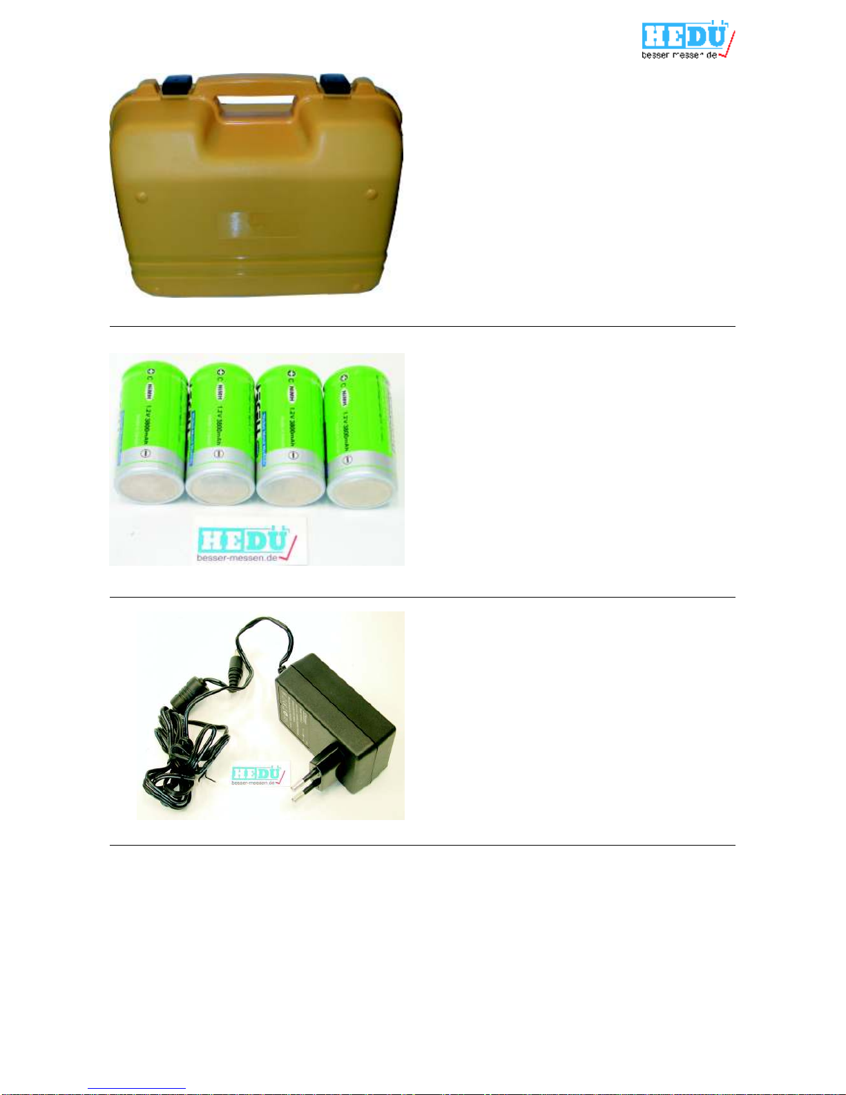
Koffer
Case
Art.-Nr. / Art.-No.
R154-1. . . . . . . . . . . . . . . . . . . . . 30,00 €
4 Akkus Typ C NiMH 1.2 V 3800 mAh
4 rechargeable batteries
Art.-Nr. / Art.-No.
R154-2. . . . . . . . . . . . . . . . . . . . . 46,00 €
Ladegerät
Charger
Art.-Nr. / Art.-No.
R154-3. . . . . . . . . . . . . . . . . . . . . 39,00 €
ALB, AND, AUT, BGR, BIH, CHE, DEU,
DNK, ESP, FIN, GRC, HRV, HUN, ITA,
LUX, MCO, MDA, MKD, NLD, NOR, POL,
PRT, ROU, SVN, SWE, TUR
Ladegerät (französische Version)
Charger (french version)
Art.-Nr. / Art.-No.
R154-17. . . . . . . . . . . . . . . . . . . . 39,00 €
BEL, CZE, FRA, SVK
2
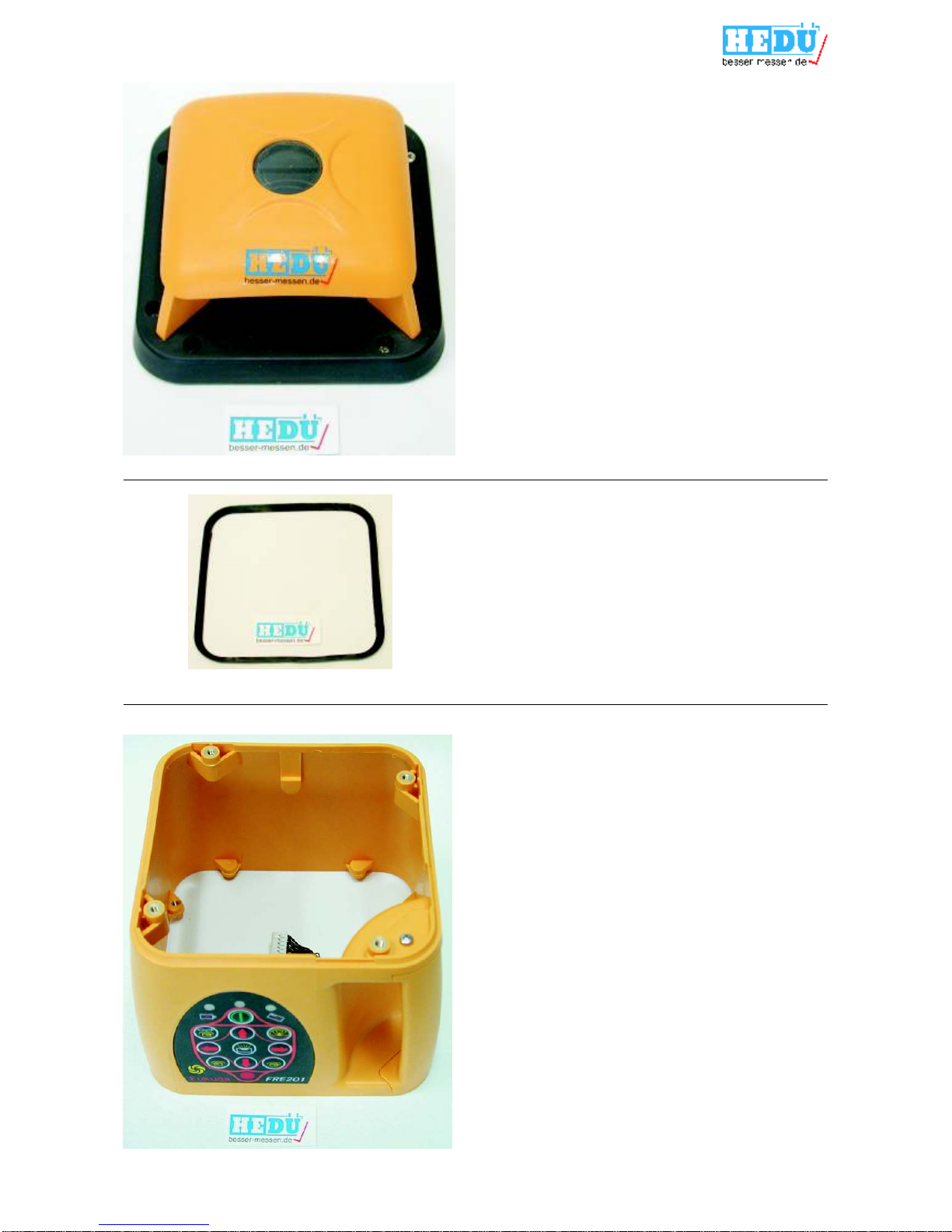
Gehäuse Oberschale
Top cover set
Art.-Nr. / Art.-No.
R154-5. . . . . . . . . . . . . . . . . . . . . 18,00 €
Oberer Dichtungsring
Upper gasket
Art.-Nr. / Art.-No.
R154-6. . . . . . . . . . . . . . . . . . . . . . 2,30 €
Gehäuse mit Griff, Tastatur und Kabel
Housing unit with handle, panel and cable
Art.-Nr. / Art.-No.
R154-7. . . . . . . . . . . . . . . . . . . . . 49,60 €
3

Gehäuse Unterschale
Underpan
Art.-Nr. / Art.-No.
R154-8. . . . . . . . . . . . . . . . . . . . . 28,00 €
Unterer Dichtungsring
Lower gasket
Art.-Nr. / Art.-No.
R154-9. . . . . . . . . . . . . . . . . . . . . . 2,30 €
4
Fernbedienung
Remote control
Art.-Nr. / Art.-No.
R154-4. . . . . . . . . . . . . . . . . . . . . 48,00 €

Steuerungsplatine
Mainboard
Art.-Nr. / Art.-No.
R154-11. . . . . . . . . . . . . . . . . . . 132,00 €
Antriebsmotor mit Halteblech, Zahnrad
und Kabel
Driving motor with stabilizing board, gear
and cable
Art.-Nr. / Art.-No.
R154-12. . . . . . . . . . . . . . . . . . . . 98,00 €
Lichtschranke
Light barrier
Art.-Nr. / Art.-No.
R154-13. . . . . . . . . . . . . . . . . . . . 32,00 €
5
Batteriedeckel
Batteriy cover
Art.-Nr. / Art.-No.
R154-10. . . . . . . . . . . . . . . . . . . . . 6,70 €

Nivelliermotor, links
X-leveling motor
Art.-Nr. / Art.-No.
R154-14. . . . . . . . . . . . . . . . . . . . 46,00 €
Nivelliermotor, rechts
Y-leveling motor
Code 25PM15-02-SZ
Art.-Nr. / Art.-No.
R154-15. . . . . . . . . . . . . . . . . . . . 46,00 €
Nivelliermotor
leveling motor
Code 2510-02-SZ2
Art.-Nr. / Art.-No.
R154-19. . . . . . . . . . . . . . . . . . . . 46,00 €
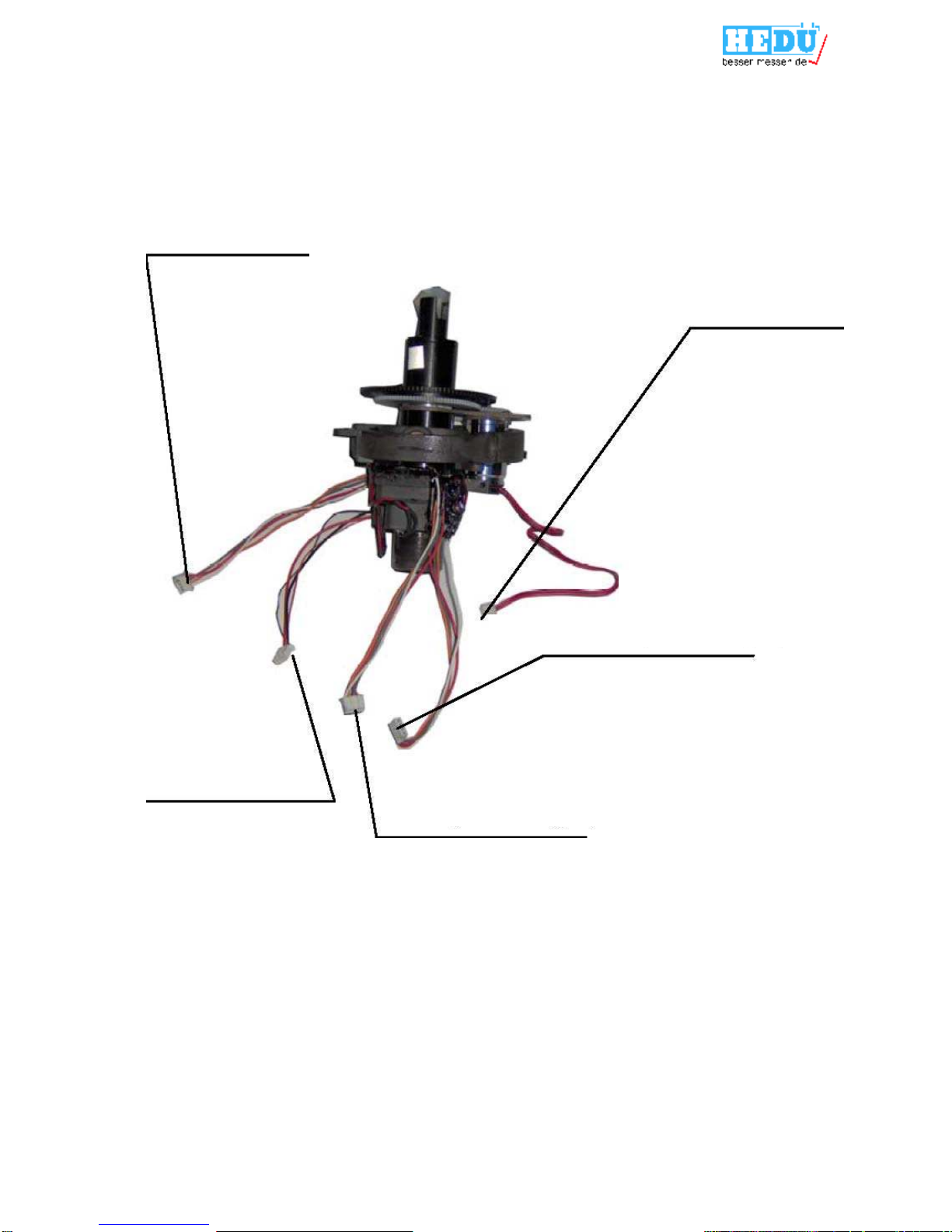
Pendel mit Prisma, Befestigungsring,
Rasterscheibe, Tilt-Sensor
Pendulum with prism, ring holder, raster,
self-alarm PCB
Code FRE101-101-Pendulum
Art.-Nr. / Art.-No.
R154-16. . . . . . . . . . . . . . . . . . . 176,00 €
6

Anschluss Gehäuse Unterschale
Connection underpan
Anschluss Lichtschranke
Connection light barrier
Anschluss Tastatur
Connection panel main housing
Anschlussplan Hauptplatine
Mainboard connection guide
Vertikallibelle
Z-sensor socket
X-Nivelliermotor
X-leveling motor
Y-Nivelliermotor
Y-leveling motor
Rechte Libelle
X-sensor socket
Laser Anschluss
Laser power plug
Linke Libelle
Y-sensor socket
Anschluss Tilt
Selt-alarm PCB
Antriebsmotor
Driving motor
7
Y-axis sensor plug
driving motor plug
Z-axis sensor plug
X-axis sensor plug
laser power plug
Anschlussplan Pendel
Pendulum connection guide
8

Instrument Checking
(1)
(2)
(3)
(4)
Place the instrument at the point of 50m in front of wall (or set a scaleplate at the point of 50m away from
the instrument), and then adjust the level of the base approximately to aim the X1 to the wall (or scaleplate),
as depicted below:
After switching on the power, use the detector measuring the h1 of X1-beam on the wall or scaleplate.
Loose the screw of the tripod ,and then turn around the instrument 180°to measure the h2 of X2-beam on
the wall or scaleplate. D-value between h1 and h2 ought to be less the 10mm.
Check the Y-beam in the same way.
9

Level adjusting (old model)
(1)
(2)
(3)
(4)
(5)
If the D-value between h1 and h2 is more than 10mm, adjust the instrument as following steps:
Press the key ON/OFF when power indicator lights, automatic leveling of instrument starts up.
Press the key ïand ðsimultaneously for 3 seconds when undervoltage indicator winks, the instrument
enters mode of adjusting.
Press the key ïor ðof X-axis repeatedly and check the position of laser beam when undervoltage
indicator is winking till the D-value between h1 and h2 is less than 10mm.
Press the key ñor òof Y-axis repeatedly and check the position of laser beam when undervoltage
indicator is winking till the D-value between h1 and h2 is less than 10mm.
Press the key ñand òsimultaneously to hold the adjustment when undervoltage indicator goes out.
10

Level adjusting (new model)
Y-axis adjustment
(1)
(2)
(3)
(4)
X-axis adjustment
(1)
(2)
(3)
(5)
Note:
If the D-value between h1 and h2 is more than 10mm, adjust the instrument as following steps:
If the instrument is set horizontally, Y-axis adjustment stands for Z-axis adjustment.
Press the key ON/OFF when power indicator lights, automatic leveling of instrument starts up.
Press the key ïand ðsimultaneously for 3 seconds when mode indicator winks, the instrument enters
mode of adjusting.
Press the key ñor òof Y-axis repeatedly and check the position of laser beam when mode indicator is
winking till the D-value between h1 and h2 is less than 10mm.
Press the key ïand ðsimultaneously to hold the adjustment when mode indicator goes out.
Press the key ON/OFF when power indicator lights, automatic leveling of instrument starts up.
Press the key ïand ðsimultaneously for 3 seconds when undervoltage indicator winks, the instrument
enters mode of adjusting.
Press the key ïor ðof X-axis repeatedly and check the position of laser beam when undervoltage
indicator is winking till the D-value between h1 and h2 is less than 10mm.
Press the key ñand òsimultaneously to hold the adjustment when undervoltage indicator goes out.
If canceling the adjustment, please shut off the instrument and then turn on it.
If the adjusting range exceed range permitted, the power indicator will wink.
11

12
Malfunctions & Eliminations (Rotary Laser)
Failures in starting up
Symptoms
After pressing the Key ON/OFF, power indicator can’t light and also the
instrument doesn’t start up.
Causesa. Poor contact of keys on the panel or panel plug.
b. Poor contact of batteries or power plug, and insufficient power,
c. Troubles of PCB
Eliminations
a. Take off the shell,and renew the panel or connect the power plug with PCB well.
b. Take down the cover of battery case to check whether there are some
dirt or rust between the spring and spring strip,and clear off them if it is
true;Recharge the batteries till power is sufficient and then detach
the shell to connect the power plug with PCB well.
c. Detach the shell to change the PCB.
No spinning of laser head.
Symptoms
The laser beam is being emitted but the laser head doesn’t rotate after instrument
is power on.
Causes
a. Center to center distance of gear is not suitable,gearing is abnormal.
b. Troubles of scanning motor.
c. Laser head has touched the optical coupler.
d. Troubles of PCB.
Eliminations
a. Take off the shell to readjust the center-to-center distance of the gear.
b. Change the scanning motor after taking off the shell.
c. Detach the shell to readjust the space between laser head and optical coupler.
d. Change the PCB.

Malfunctions & Eliminations (Laser Detector)
No responses of detector
Symptoms
Press the Key ON/OFF, the LCD doesn’t display.
Causes
a. Install the batteries according to the wrong electrode.
b. Panel plug drops out.
Eliminations
a. Take off the cover of battery case to install the batteries correctly.
b. Detach the panel cover of detector to insert the plug again.
No sound of buzzer.
Symptoms
There is no sound of buzzer after pressing any keys on the panel.
Causes
Buzzer plug drops out.
Eliminations:
Connect the buzzer plug with the PCB well.
13

Top Cover Set
14

Housing Set
15

Undperpan Set
16

Pendulum
Y-sensor X-sensor
Z-sensor
17
Other manuals for FRE201
1
This manual suits for next models
1
Table of contents
Other HEDÜ Laser Level manuals


