Heiko JS025-A1 User manual

SERVICE MANUAL
Wall Mounted Type
DC Inverter
JS025-A1
JS035-A1
Model No.
This service information is designed for experienced repair technicians only and is not designed for use by the general public.
It does not contain warnings or cautions to advise non-technical individuals of potential dangers in attempting to service a product.
Products powered by electricity should be serviced or repaired only by experienced professional technicians. Any attempt to service or
Repair the product or products dealt with in this service information by anyone else could result in serious injury or death
WARNING
All rights reserved. Unauthorized copying and distribution is a violation of law
Version V1 Date 2020-11-24

Table of contents
Domestic air conditioner
Contents
1. Introduction............................................................................................ 1
2. Features ................................................................................................ 7
3. Specifications ........................................................................................ 8
4. Sensors list............................................................................................ 9
5. Piping diagrams.....................................................................................10
6. Printed Circuit Board Connector Wiring Diagram..................................11
7. Functions and Control ...........................................................................
8. Dimensional drawings ...........................................................................
9. Center of gravity ....................................................................................
10. Service diagnosis................................................................................
11. Wiring diagrams ..................................................................................
14
40
26
25
25

Domestic air conditioner

lntroduction
1.2 Safety Cautions
2 2 2;
2)
C
2 Domestic air conditioner

Warning
1.2.3 Cautions Regarding Products after Repair
Warning
lntroduction
A
�
I
3 Domestic air conditioner

lntroduction
Warning
o
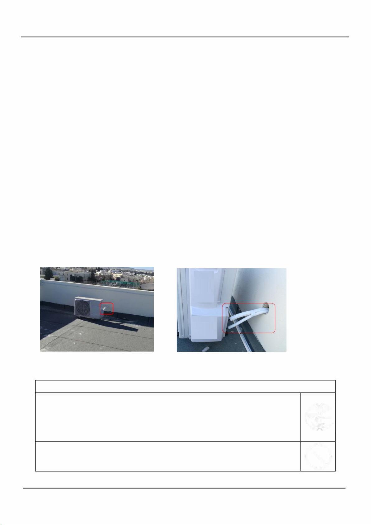
4 Domestic air conditioner

lntroduction
5 Domestic air conditioner

o
lcons are used to attract the attention of the reader to specific information. The meaning of each icon is described in
the table below:
DNote
6

Specifications
Domestic air conditioner
2.Features
Super quiet: Lower noise operation condition
A-PAM DC inverter:With adoption of S-TYPE,S-PAM and PHASE control technology to works more
stably at low-frequency,and is more energy-saving,mor powerful at high frequency.
Long distance air supplying: The indoor units is improved by the optimized motor, fan and air duct so as to
provide long distance airflow with 12m+ maximum.
-15 Heating: When -15 can still heating natural
10 heating maintenance:Heating Holding 10 temperature
Comfortable sleep The setting temperature and the indoor noise can be adjusted to a more comfortable
level when you set the “sleep mode” during night sleep.
Super match:One outdoor unit can match two or more indoor unit.
DIY auto mode: Adjust the last fixed operation mode automatically.
Turbo mode: Quick cooling or heating
Auto restart: Automatic return to previous operation conditions after sudden power blackout
24 hours timer: Use the timer function to set on,or off,or from on to off,or from off to on.
Integrative valve cover:The valve cover is Integrative.
2-way piping design: The pipe can shoot out both from left or right side.
Easy clean design: The panel is easy to wash and the airflow vents can be detached easily
Double 8 display:The display is Double 8 mode.
7

Specifications
Domestic air conditioner
3. Specifications
NOMINAL DISTRIBUTION SYSTEM VOLTAGE
1/esahP
05zHycneuqerF
032VegatloV
NOMINAL CAPACITY and NOMINAL INPUT
heating
cooling
Capacity rated KW
Btu/h
WK
)detaR(noitpmusnoCrewoP
W/W
POCS/REES
107
hWK
noitpmusnocygrenelaunnA
h/³m
lavomeRerutsioM
TECHNICAL SPECIFICATIONS
103*691*078mmD*W*HsnoisnemiD
Packaged Dimensions 983*382*259mmD*W*H
5.9GK/thgieW
0.21GK/thgiewssorG
//roloC
Sound level
Sound
peessure(Hi/Mid/Lo)
Sound power(high)
39/33/26
55
38/32/25
dB(A)
White
dB(A)
1.2*10 ³
-1.6*10 ³
-
2.6(0.8-3.2)
8870
(2730-10920)
0.65
8.5
25 35
144
3.5(1.0-4.0)
11940
(3410-13650)
0.87
8.5
731
3.2(0.8-4.2)
10920
(2730-14330)
0.80
4.6
854
4.2(1.0-5.2)
14330
(3410-17740)
1.10
4.6
53
heating
cooling

Specifications
Domestic air conditioner
TECHNICAL SPECIFICATIONS-PARTS
cooling heating
Fan
nafwolfssorCepyT
0303WtuptuorotoM
Air flow rate(high) m³/h
Speed(Hi/Mid/Lo)
Heat exchanger
Type ML fin- 7HI-HX tube
4.1*41*3hctif*egats*tnemgeS
drawnwoD,latnoziroH,tfeL,thgiRlortnocnoitceridriA
Air filter
Removable/Washable/Mildew Proof
Temperature control
Microcomputer Control
0010401715YledomrellortnocetomeR
Note: the data are based on the conditions shown in the table below
htgnelgnipiPgnitaehgnilooc
Indoor: 27 DB/19 WB
Outdoor: 35 DB/24 WB
Indoor:20 DB
Outdoor: 7 DB/6 WB 5m
4 Sensors list
type Description Qty
rofdesustIrosnesmooR erutarepmetmoorgnitceted
Pipe sensor Its used for detecting temperature of evaporator
1
Conversation formulae
Kcal/h= KW×860
Btu/h= KW×3414
cfm=m³/min×35.3
600
rpm 1100/900/700 1200/1000/800
650
25 35
cooling heating

Piping diagrams
Domestic air conditioner
5ˊPiping diagrams
10

Connector Wiring diagrams
Domestic air conditioner
6. Printed Circuit Board Connector Wiring Diagram
Connectors
Note: Other designations
PCB(1) (Indoor Control PCB)
1) SW1 Connector for Forced operation ON / OFF switch
2) SW2 1 Select remote code A or B, 2 Select room card able or disable 33 and 35 ,
3) RV1 Varistor0
4) FUSE1 Fuse 3.15A/250VAC
11
PCB(1) (Control PCB) For JS025-A1 and JS035-A1
1) CN9 Connector for fan motor
2) CN6 Connector for heat exchanger thermistor and Room temperature thermistor
3) CN5、CN5’ Connector for UP&DOWN STEP motor
4) CN11、CN11’ Connector for RIGHT&LEFT STEP motor
5) CN21(white line)、CN52(black line) Connector for indoor terminal N and L
6) CN8 Connector for display board
7) CN23 (red line) Connector for communicate between the indoor board and the outdoor board
8) CN36 Connector for long-range control
9) CN34 Connector for wifi Module
10) CN2 Connector for wired controller
11) CN51 Connector for room card
Note: Other designations
PCB(1) (Indoor Control PCB)
1) CN14 Connector for Forced operation ON / OFF switch
2) FUSE1 Fuse 3.15A/250VAC
OFF ON 3 ON ON OFF OFF
1 A B 4 ON OFF ON OFF
2 N-RC RC 35 33 26 23
OFF OFF ON ON
OFF ON OFF ON
325/498 324 387 317
J2
DISPLAY SERIES
UNIT MODEL DISPLAY MODEL
0011800387D
0011800387D
UNIT MODEL PCB MODEL
JS025-A1
JS035-A1
0011801123
(23)
0011801123
(26)
J1
JS025-A1
JS035-A1
3,4 Select 23 26

Domestic air conditioner
12
CN8
CN9
CN21
CN36
CN23
CN6
CN52
CN5’
CN14
CN2
CN34
CN15
C
N11
’
‘’’
C
N51
CN5
C
N11
‘’’
PCB

Functions and Control
Domestic air conditioner
7.Funcitions and Control
7.1 Main functions and control specification
7.1.1 Automatic operation
When the running mode is turned to automation after starting the system, the system will first determine
the running mode according to the current room temperature and then will run according to the determined
mode. Tr in the following selection conditions means room temperature, Ts means setting temperature, Tp
means temperature of indoor coil pipe
Tr≥Ts-3℃Choose Cooling Mode
Tr<Ts-3℃Choose Heating Mode
After turning to the automation mode, the running mode can be switched between cooling mode, fan
mode and heating mode according to the change of the indoor ambient temperature. But the automatic
conversion between cooling mode and heating mode must be conducted after 15 minutes.
7.1.2 Cooling operation mode
Temperature control range: 16 ---30
Temperature difference: 1
* Control features: When Tr input airflow >Ts set temperature , the compressor will be opened, the indoor
fan will operate at the set speed and the mode signal will be sent to the outdoor system. When Tr input
airflow Ts set temperature , the compressor will be opened, the indoor fan will operate at the set speed
and the mode signal will be sent to the outdoor system. The system will keep the original status if Tr= Ts.
Airflow speed control: (temperature difference 1 )
Automatic: When Tr Ts+3 , high speed.
When Ts+1 Tr<Ts+3 , medium speed
When Tr<Ts+1 , low speed
When the sensor is off, low speed
When the airflow speed has no delay from the high to low switching, the speed should be delayed for 3
minutes (remain at high speed for 3 minutes.) before the next switch.Manus: When the system is operating,
you can set the high, medium or low speed manually. (When the sensor is on or off, the system will change
the speed 2 seconds after receiving the signal.)*Airgate location control: the location for the airgate can be
set according to your needs.*Defrosting function: preventing the frosting on the indoor heat exchanger
(when cooling or dehumidifying). When the compressor works continuously for 6 minutes and the temperature
of the indoor coils has been below one centigrade for 10 seconds, the compressor will be stopped and the
malfunction will be recorded in the malfunction list. The indoor system will continue to run. When the temperature
of the indoor coil is raised to 9℃, the compressor will be restarted again (the requirement of 3 minutes’ delay
should be satisfied.)
* timing system on/off function.
* Dormant control function.
13
7.1.3 Dehumidifying mode.
* temperature control range: 16---30℃
* temperature difference: ±1℃

Functions and Control
Domestic air conditioner
Control feature: send the dehumidifying signal to the outdoor system.
When Tr>Ts+2℃, the compressor will be turned on, the indoor fan will operate at the set speed.
When Tr is between the Ts and Ts+2℃, the outdoor system will operate at the high dehumidifying
frequency for 10 minutes and then at the low dehumidifying mode for six minutes. The indoor fan will
operate at low speed.
When Tr< Ts-1.5℃, the outsystem will be stopped, the indoor fan will be stopped for 3 minutes and then
turned to the low speed option.
All the frequency converses have a ±1℃difference.
* Wind speed control: Automatic:
When Tr≥Ts+ 5℃, high speed.
When Ts+3℃≤Tr< Ts+5℃, medium speed.
When Ts+2℃≤Tr< Ts+3℃, low speed.
When Tr<Ts+2℃, light speed.
If the outdoor fan stopped, the indoor fan will be paused for 3 minutes.
If the outdoor fan stopped for more than 3 minutes and the outdoor system still operates, the system will
be changed into light speed mode.
When the airflow speed has no delay from the high to low switching, the speed should be delayed for 3
minutes (remain at high speed for 3 minutes.) before the next switch.
Manual: When the sensor is off or Tr< Ts+3℃, the manual operation can not be made. (obligatory
automatic operation.)
*Airgate location control: the location for the airgate can be set according to your needs.
*Defrosting function: preventing the frosting on the indoor heat exchanger (when cooling or
dehumidifying). When the compressor works continuously for 6 minutes and the temperature of the
indoor coils has been below 1℃for 10 seconds, the compressor will be stopped and the malfunction
will be recorded in the malfunction list. The indoor system will continue to run. When the temperature of
the indoor coil is raised to 9℃, the compressor will be restarted again (the requirement of 3 minutes’
delay should be satisfied.)
* Coil protection (synchronic overheating protection) are installed for the four directions latch
malfunctions when dehumidifying.
* Timing system on/off function.
* Dormant control function.
Ts+20AD 值(约 2℃)
Ts
区 段 1
(COOL)
区段 2(DRY)
区段 3(停机)
Ts-12AD 值(约 1.5℃)
Ts+3AD 值(约 0.5℃)
14

Functions and Control
Domestic air conditioner
15
7
.1.4 Heating operation mode.
*temperature control range: 16---30℃
* temperature difference: ±1℃
* control feature: the temperature compensation is automatically added and the system will send th
e
heating signals to the outdoor system.
If Tr+0.5℃≤Ts, the outdoor compressor is turned on, the indoor fan will be at the cold air proof mode.
If Tr>Ts+1.5℃, the outdoor system is turned off, the indoor fan will be at the heat residue sending mode
.
*Indoor fan control
manual control: You can choose high, medium, low and automatic speed control.
Automatic: When Tr<Ts, high speed.
When Ts≤Tr≤Ts+2℃, medium speed.
When Tr> Ts+2℃, low speed.
When the airflow speed has no delay from the high to low switching, the speed should be delayed for
3
minutes (remain at high speed for 3 minutes.) before the next switch.
*Airgate location control: the location for the airgate can be set according to your needs.
Coldair proof operation
1. The fan control functions as below:
* Residue heat sending. The indoor fan will send the residue heat at a low speed for 20 seconds.
If other conditions are satisfied, when the compressor stops, the indoor system will operate at a ligh
t
speed. The indoor fan will stop when the coil temperature is below the THHOT0.
* Defrosting. When the system receives the defrosting signal from outdoors, the indoor fan will stop an
d
the indoor temperature display won’t change. At the time, any indoor coil malfunctions will be neglected
.
When the outdoor defrosting finishes, the coil malfunction will still be neglected until the compressor ha
s
been started up for 30 seconds. The indoor temperature display will not change and the syste
m
operates at the cold air proof mode.
* Automatic heating temperature compensation: when the system enters the heating mode, th
e
temperature compensation (4℃) will be added. When the status is switched off, the compensation wil
l
be erased.
7
.1.5 Strength operation
The system enters the mode after receiving the ‘strength signal’.
35
低风
23
停止
设定
25(THHOT1)
16(THHOT0)
微弱风
35(THHOT2)
中风
37(THHOT4)
37(THHOT3)
15

Functions and Control
Domestic air conditioner
Send strength operation signal to the outdoor system.
The mode change finishes the strength operation.
Entering ‘mute’, you can have normal operation or signal control such as timing to finish the strength
operation.
When the system is at the automatic option with the strength/ mute function, if the system enters the
cooling mode, the cooling strength/ mute function will be offered; if the system enters the heating mode,
then the heating strength/ mute function will be offered; if the system enters the airflow mode, there will
be no strength/ mute function.
7.1.6 Mute operation
The system enters the mode after receiving the ‘mute signal’.
a. Mute heating: the airflow speed is slight, the system sends the mute signal to the outdoor system.
b. mute cooling: the airflow speed is slight, the system sends the mute signal to the outdoor system.
When the compressor operates, the airflow speed is mute speed. EEPROM is adaptable.
Mute operation can not work under the dehumidifying and airflow-sending operation.
7.1.7 Air refreshing(This model does not choose)
After receiving the signal from the remote control, (HV series: the background light of the ‘health’ logo is
green. HS series: the ‘health’ indicator will be lighted). If the fan operates, the Nano-Aqua operates to
realize the ions sending function.
If the indoor fan stops, the Nano-Aqua is turned off.
When the Nano-Aqua is turned off, if the air refreshing system is turned on, the Nano-Aqua will be
turned on when the fan operates.
7.1.8 Timing
You can set 24 hours’ on/off timing accordingly. After the setting, the timing indicator will be lightened.
Also, the light will be turning off after the timing is finished. The followings are several timing methods.
1.system /on timing: The timing indicator will be lightened and the indoor system is under the waiting
mode. The light will be turned off when the timing is finished and the rest of the system will operate
under a normal condition. The timing starts since the last reception of the timing signal.
2.system /off timing: When the system is turned on, the timing indicator is lightened, the rest of the
system will operated under a normal condition. When set time comes, the indicator light will be turned
off and the system will be turned off. If you have set the dormant functions, the order of your settings will
be operated according to the timing settings.
3 .system /on and off timing: The settings will be completed according to the orders..
7.1.9 Dormant operation
The dormant timing is an eight hours unadaptable one. The timing signs are shown on the display
board,if the model have timing or sleeping signs.
2.1 Under the cooling/ dehumidifying operation, after the setting of the dormant operation, the set
temperature will be raised for 1 centigrade after 1 hour’s operation and will be raised for 1 centigrade 1
hour later. The system will keep this status for 6 hours and then close.
2.2 Under the heating mode, after the setting of the dormant operation, the setting temperature will fall 2
centigrade after 1 hour’s operation and will fall 2 centigrade 1 hour later. 3 hours after the preceding
16

Functions and Control
Domestic air conditioner
operations, the set temperature will be raised for 1 centigrade and the system will keep this status for 3
hours and then close down.
2.3 During the dormant time, except the change of the system mode or a new press on the dormant
setting keys, the timing of the 8 hours dormancy will take the first timing as the start time, any presses
on other keys will not affect the original timing.
2.4 Indoor fan control under the dormant operation.
If the indoor fan is at the high speed before the dormant operation setting, the speed will be turned to
medium after the setting. If the fan is at the medium speed before the dormant setting, the speed will be
turned to low after the setting. If the fan is at the low speed before the dormant setting, the speed will not
change.
7.1.10 Urgent on/off input
Press the urgency button the buzzer will ring. The system will enter the automatic mode if you don’t
press the button for more than 5 seconds.
Under the system off mode, if you press the urgency key for 5 to 10 seconds, the system will start the
test operation.
Under the system off mode, if you press the urgency key for 10 to 15 seconds, the display screen will
show the resume of the last malfunction.
If the system is under operation, the press on the urgency key will stop it.
Under the system off mode, the display screen will show automatic running sign.
Under the system off mode, the system will not receive the remote control signal if the press on the
urgency key doesn’t last for 15 seconds or if the key is loosened.
Urgency operation: If you press the urgency key for less than 5 seconds, the buzzer will ring when you
press the on/off key. The system will enter the urgency operation when the urgency key is loosened.
The urgency operation is fully automatic.
Test operation.
The inlet temperature sensor doesn’t work, the indoor fan and the indoor air direction board motor works
synchronically. High speed airflow, cooling, outdoor system on, etc, will send the ambient temperature
30 centigrade and coil temperature 16 centigrade information to the outdoor system.
Test operation
The defrost protection of the evaporator doesn’t work.
The temperature control doesn’t work.
The test operation will be finished in 30 minutes.
The test operation can be stopped by the relative commands from the remote control.
7.1.11 Low load protection control
In order to prevent the frosting of the indoor heat interaction device, the outdoor system will be stopped
if the indoor heat interaction temperature is below 1℃centigrade for 5 minutes, but the fan will continue
to operate. The outdoor system will be started again when the heat interaction temperature is above 9
centigrade and the system has been stopped for 3 minutes. The malfunction will be stored in the
malfunction resume and will not be revealed
17

Functions and Control
Domestic air conditioner
18
7
.1.12 High load protection control
The outdoor system will be stopped if the coil temperature is above 63℃for 2 minutes. The indoor fa
n
will be controlled by the thermostat. The outdoor system can be restarted when the coil temperature i
s
below 45℃and the system has been stopped for 3 minutes. The malfunction will be stored in th
e
malfunction resume and will not be revealed.
7
.1.13 Abnormal operation of indoor system
When the outdoor system operates, if the indoor system operation differs from the outdoor system, th
e
abnormal operation malfunction will be reported. 10s after the report, the indoor system will be closed.
Outdoor system mode Indoor system mode conflicts
cooling heating yes
cooling cooling no
cooling airflow no
heating heating no
heating airflow yes
heating cooling yes
7
.1.14 Malfunction list resume.
Nothing is presented if there is no code list.
The malfunction display will automatically finish in 10 seconds.
The remote control only receives the signals for stop. According to the signals, the malfunction resum
e
presentation finishes.
The resume restores after the power supply restores.
7
.1.15 Abnormality confirmation approaches
1. indoor temperature sensor abnormality:
Under the operation, the normal temperature ranges from 120 degree to -30 degree. When th
e
temperature goes beyond this range, the abnormality can be confirmed. If the temperature goes bac
k
into the range, the system will automatically resume.
2 .indoor heat interaction sensor abnormality:
Under the operation, the normal temperature ranges from 120 degree to -30 degree. When th
e
temperature goes beyond this range, the abnormality can be confirmed. If the temperature goes back
into the range, the system will automatically resume.
3 .indoor malfunction:
Out door malfunction: When the indoor system receives the outdoor malfunction codes, it will store th
e
code into E2 for the malfunction list resume. The indoor system will continue to operate according to th
e
original status, the malfunction code will not be revealed or processed.
4. transmission abnormality:
If the indoor system can’t receive the outdoor system for 8 minutes, the communication abnormality ca
n
be confirmed and reported and the outdoor system will be stopped.
This manual suits for next models
1
Table of contents
Other Heiko Inverter manuals